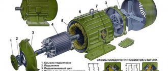
Design features and diagram of a single-phase 220V electric motor
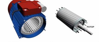
The main elements of a single-phase motor are the rotor and stator.
The first component is mobile during operation, the second is at rest. The stator is equipped with two types of winding: main and auxiliary. Otherwise they are called working and starting. Both types are located at an angle of 90 degrees in the core and are securely fixed in the grooves. The main winding makes up the majority, and the auxiliary winding is allocated only 30–35%. As for the rotor design, it consists of rods made of non-ferrous metals. At the ends, the elements are closed with special rings. The free space between the rods is filled with aluminum alloy. Because of its hollow appearance, experts and designers called the rotor of a 1-phase motor a “squirrel cage”.
The operating principle of a single-phase 220 V electric motor.
A magnetic field is generated in the stator of a 220 V single-phase electric motor. This is the impulse that drives the rotor. To imagine how an electric motor functions, it is worth simulating the following situation.
For example, there is no voltage in the starting winding. The formation of a magnetic field can be started by connecting the main winding to the network. Its work is based on pulsation, while the space remains at rest. The magnetic field is divided into two parts, each of which rotates in directions opposite to each other, at the same frequency. When the rotor is given an initial rotation, the engine will increase it over time. In this case, the frequency of the element and the magnetic field itself differs. The difference in indicators is defined as slip.
A driving force arises from magnetic fluxes. This is the law of electromagnetic induction. The driving force generates two types of current. One of them is reverse, the second is direct. The rotor speed is directly proportional to the slip rate. According to Ampere's law, a magnetic field, when interacting with a reverse current, creates rotation.
Connection
Calculating the values of their capacitances is relatively simple: for the working one 0.75 μF per 1 kW of power, for the starting one - 2.5 times more. Its structure is slightly different from a conventional single-phase asynchronous motor.
A circuit with a working, always-on capacitor works better in nominal mode, but has mediocre starting characteristics. The operating voltage of these capacitors should be 1.5 times higher than the network voltage, that is, for network B we take capacitors with an operating voltage of B and higher.
But despite this, they are widely used in the production of household appliances. These motors have lower efficiency values.
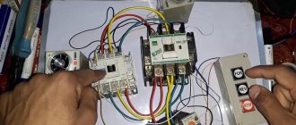
After assembling the electromagnetic starter circuit, you should connect the power section. Its structure is slightly different from a conventional single-phase asynchronous motor. Its power can range from five to ten kilowatts. In addition to the presence of two phases, it is required that one winding be shifted relative to the other by a certain angle.
We recommend: current volumes and standards of electrical equipment testing
Operating principle of a commutator motor
Starting scheme: Starting is carried out by a magnetic field, which rotates the moving part of the motor. Next example.
Single-phase asynchronous electric motors Design and principle of operation The power of such a single-phase motor B can, depending on the design, range from 5 W to 10 kW. On which of them there is no difference, the direction of rotation does not depend on it. Look at the photo and you can clearly see that the wire cross-sections are different. When connecting the device in question, several types of connections are made. That is, if the auxiliary winding of a single-phase motor is starting, its connection will occur only during the start-up, and if the auxiliary winding is a capacitor, then its connection will occur through a capacitor, which remains turned on during engine operation.
Connection diagram for a 220 Volt commutator motor
These electricity ratings are available in all residential premises in our country, and as a result, single-phase motors are extremely popular. We need an initial push. Current is supplied to the rotor windings through brushes in contact with the commutator plates, to which the ends of the rotor windings are connected. Connection diagram 2 Connecting an asynchronous single-phase electric motor to the network.
The function of the centrifugal switch is to cut off the starting phase when the rotor reaches its rated speed. Further rotation of the rotor is ensured by the pulsating magnetic field of the working phase, as already described in the previous paragraph. Two and three-phase motors It is possible to connect a 2 or 3-phase motor to a single-phase power source. how to connect a three-phase motor to a single-phase network
Connecting a three-phase 380 volt motor
There is nothing complicated here at all. There are three phases, there are three motor terminals and a switch
The zero point (where three windings are connected, beginning or ending - as I said above, it is absolutely unimportant what we call the terminals of the windings) in a star connection scheme, there is no need to connect the windings to the neutral wire. That is, to connect a three-phase motor to a three-phase 380 volt network (if the motor is 220/380), you need to connect the windings in a star configuration, and supply only three wires with three phases to the motor
And if the engine is 380/660 volts, then the winding connection diagram will be a triangle, but there is definitely nowhere to connect the neutral wire.
Changing the direction of rotation of a three-phase motor shaft
Regardless of whether it is a capacitor switching circuit or a full three-phase one, to change the shaft rotation you need to swap any two windings. In other words, swap any two wires.
What I would like to dwell on in more detail. When we calculated the capacity of the working capacitor, we used the rated current of the motor. Simply put, this current will only flow in the motor when it is fully loaded. The less the motor is loaded, the lower the current will be, so the capacity of the working capacitor obtained by this formula will be the MAXIMUM POSSIBLE capacity for a given motor. What is bad about using the maximum capacity for an underloaded motor is that it causes increased heating of the windings. In general, something has to be sacrificed: a small capacity does not allow the engine to gain full power; a large capacity, when underloaded, causes increased heating. Usually in this case, I suggest such a solution - to make working capacitors from four identical capacitors with a switch or a set of switches (which will be more accessible). Let's say we calculated a capacitance of 40 µF. This means that for work we need to use 4 capacitors of 10 μF each (or three capacitors of 10, 10 and 20 μF) and, depending on the load, use 10, 20, 30 or 40 μF.
One more point about starting capacitors. Capacitors for AC voltage are much more expensive than capacitors for DC voltage. Using capacitors for DC voltage in AC networks is highly discouraged due to the fact that capacitors explode. However, for engines there is a special series of Starter capacitors, designed specifically to work as starting capacitors. It is also prohibited to use Starter series capacitors as working capacitors.
And in conclusion, it is necessary to note this point - there is no point in achieving ideal values, since this is only possible if the load is stable, for example, if the engine is used as a hood. An error of 30-40% is normal. In other words, capacitors must be selected so that there is a power reserve of 30-40%.
Connection diagrams for single-phase asynchronous motors
With starting winding
To connect a motor with a starting winding, you will need a button in which one of the contacts opens after switching on. These opening contacts will need to be connected to the starting winding. In stores there is such a button - this is PNDS. Its middle contact closes for the holding time, and the two outer ones remain in a closed state.
Appearance of the PNVS button and the state of the contacts after the “start” button is released"
First, using measurements, we determine which winding is working and which is starting. Typically the output from the motor has three or four wires.
Consider the option with three wires. In this case, the two windings are already combined, that is, one of the wires is common. We take a tester and measure the resistance between all three pairs. The working one has the lowest resistance, the average value is the starting winding, and the highest is the common output (the resistance of two windings connected in series is measured).
If there are four pins, they ring in pairs. Find two pairs. The one with less resistance is the working one, the one with more resistance is the starting one. After this, we connect one wire from the starting and working windings, and bring out the common wire. A total of three wires remain (as in the first option):
- one from the working winding is working;
- from the starting winding;
- general.
We work further with these three wires - we use them to connect a single-phase motor.
With all these
Connecting a single-phase motor with a starting winding via the PNVS button Connecting a single-phase motor
We connect all three wires to the button. It also has three contacts. Be sure to place the starting wire on the middle contact (which closes only during the start), the other two - on the outer ones (arbitrarily)
We connect a power cable (from 220 V) to the extreme input contacts of the PVNS, connect the middle contact with a jumper to the working one (note! not to the common one). That's the whole circuit for switching on a single-phase motor with a starting winding (bifolar) through a button
Condenser
When connecting a single-phase capacitor motor, there are options: there are three connection diagrams and all with capacitors. Without them, the engine hums, but does not start (if you connect it according to the diagram described above).
Connection diagrams for a single-phase capacitor motor
The first circuit - with a capacitor in the power supply circuit of the starting winding - starts well, but during operation the power it produces is far from rated, but much lower. The connection circuit with a capacitor in the connection circuit of the working winding gives the opposite effect: not very good performance at start-up, but good performance. Accordingly, the first circuit is used in devices with heavy starting (concrete mixers, for example), and with a working condenser - if good performance characteristics are needed.
Circuit with two capacitors
There is a third option for connecting a single-phase motor (asynchronous) - install both capacitors. It turns out something between the options described above. This scheme is implemented most often. It is in the picture above in the middle or in the photo below in more detail. When organizing this circuit, you also need a PNVS type button, which will connect the capacitor only during the start time, until the motor “accelerates”. Then two windings will remain connected, with the auxiliary winding through a capacitor.
Connecting a single-phase motor: circuit with two capacitors - working and starting
When implementing other circuits - with one capacitor - you will need a regular button, machine or toggle switch. Everything connects there simply.
Selection of capacitors
There is a rather complex formula by which you can calculate the required capacity accurately, but it is quite possible to get by with recommendations that are derived from many experiments:
- The working capacitor is taken at the rate of 0.7-0.8 µF per 1 kW of engine power;
- starting - 2-3 times more.
The operating voltage of these capacitors should be 1.5 times higher than the network voltage, that is, for a 220 V network we take capacitors with an operating voltage of 330 V and higher. To make starting easier, look for a special capacitor in the starting circuit. They have the words Start or Starting in their markings, but you can also use regular ones.
Changing the direction of motor movement
If, after connecting, the motor works, but the shaft does not rotate in the direction you want, you can change this direction. This is done by changing the windings of the auxiliary winding. When assembling the circuit, one of the wires was fed to the button, the second was connected to the wire from the working winding and the common one was brought out. This is where you need to switch the conductors.
What it might look like in practice
Option 2: reconnecting the starting winding (single-phase motor 220V)
The second way to organize the reverse of a 220 Volt asynchronous motor is to swap the beginning and end of the starting winding. This is done by analogy with the first option:
- Of the four wires coming out of the motor box, find out which of them correspond to the starter winding taps.
- Initially, end B of the starting winding was connected to the beginning C of the working winding, and beginning A was connected to the starting-charging capacitor. You can reverse a single-phase motor by connecting the capacitance to terminal B, and the beginning of C to the beginning of A.
After the actions described above, we get a diagram as in the figure above: points A and B have swapped places, which means the rotor began to turn in the opposite direction.
Design features and diagram of a single-phase 220V electric motor.
The main elements of a single-phase motor are the rotor and stator. The first component is mobile during operation, the second is at rest. The stator is equipped with two types of winding: main and auxiliary. Otherwise they are called working and starting. Both types are located at an angle of 90 degrees in the core and are securely fixed in the grooves.
The main winding makes up the majority, and the auxiliary winding is allocated only 30–35%. As for the rotor design, it consists of rods made of non-ferrous metals. At the ends, the elements are closed with special rings. The free space between the rods is filled with aluminum alloy. Because of its hollow appearance, experts and designers called the rotor of a 1-phase motor a “squirrel cage”.
How to calculate capacity
The capacity of the capacitor, which is installed in the connection circuit of a three-phase electric motor connected to a 220V network, depends on the circuit itself. There are special formulas for this.
Cр = 2800•I/U, where Ср is capacitance, I is current, U is voltage. If a triangle connection is made, then the same formula is used, only the coefficient of 2800 changes to 4800.
I would like to draw your attention to the fact that the current strength (I) is not indicated on the motor tag, so it will need to be calculated using this formula:
I = P/(1.73•U•n•cosф), where P is the power of the electric motor, n is the efficiency of the unit, cosф is the power factor, 1.73 is a correction factor, it characterizes the relationship between two types of currents: phase and linear.
Since most often the connection of a three-phase motor to a single-phase 220V network is made in a triangle, the capacitance of the capacitor (working) can be calculated using a simpler formula:
C = 70•Pn, here Pn is the rated power of the unit, measured in kilowatts and indicated on the device tag. If you look at this formula, you can understand that there is a fairly simple relationship: 7 uF per 100 W. For example, if a 1 kW motor is installed, then it requires a 70 µF capacitor.
How to determine whether the capacitor is correctly selected? This can only be checked in operating mode.
- If during operation the motor overheats, it means that the capacity of the device is greater than required.
- Low engine power means the capacity is underestimated.
Even calculations can lead to the wrong choice, because the operating conditions of the motor will affect its operation. Therefore, it is recommended to start the selection with low values, and, if necessary, increase the indicators to the required (nominal) values.
As for the starting capacity, what is first taken into account is what starting torque is needed to start the electric motor
I would like to draw your attention to the fact that the starting capacitance and the capacitance of the starting capacitor are not the same thing. The first value is the sum of the capacitances of the working and starting capacitors
As workers, you can use paper, metallized or film analogues. In this case, it is necessary to take into account the fact that the permissible voltage should be one and a half times the nominal voltage. As you can see, choosing the exact capacitor for an electric motor is quite difficult. Even calculation is an imprecise process.
Source
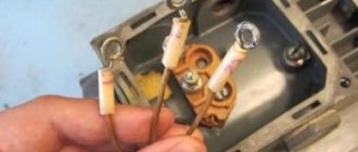
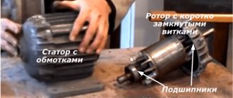
Winding check
In most cases, the problem can be detected by its appearance and characteristic odor (see Figure 1). If the fault cannot be determined empirically, we proceed to diagnostics, which begins with a continuity test. If one is found, the engine is disassembled (this process will be described separately) and the connections are thoroughly inspected. When no defect is detected, a break can be established in one of the coils, which requires rewinding.
If the continuity test does not show a break, you should proceed to measuring the winding resistance, taking into account the following nuances:
- the insulation resistance of the coils to the housing should tend to infinity;
- for a three-phase drive, the windings must show the same resistance;
- For single-phase machines, the resistance of the starting coils exceeds the readings of the working windings.
In addition, it should be taken into account that the resistance of the stator coils is quite low, so to measure it it makes no sense to use devices with a low accuracy class, such as most multimeters. You can correct the situation by assembling a simple circuit using a potentiometer with the addition of an additional power source, for example a car battery.
Circuit for measuring winding resistance
The measurement procedure is as follows:
- The drive coil is connected to the circuit presented above.
- The potentiometer sets the current to 1 A.
- The coil resistance is calculated using the following formula: , where RK and UPIT were described in Figure 2. R is the resistance of the potentiometer, and is the voltage drop across the measured coil (shown by a voltmeter in the diagram).
It is also worth talking about a technique that allows you to determine the location of the interturn short circuit. This is done as follows:
The stator, freed from the rotor, is connected through a transformer to a reduced power supply, having previously placed a steel ball on it (for example, from a bearing). If the coils are working, the ball will move cyclically along the inner surface without stopping. If there is an interturn short circuit, it will “stick” to this place.
AC brushed motor
Consider a brushed AC motor. Universal commutator motors can be powered from both AC and DC sources. They are often used in power tools, sewing and washing machines, meat grinders - where reverse is needed, adjustment of the rotor speed or its rotation at a frequency of more than 3000 rpm.
The stator and rotor windings of a commutator motor are connected in series. Current is supplied to the rotor windings through brushes in contact with the commutator plates, to which the ends of the rotor windings are connected.
Reversing a single-phase motor with a commutator is carried out by changing the polarity of the stator or rotor windings being connected to the network, and the rotation speed can be adjusted by changing the amount of current in the windings.
The main disadvantages of such an engine:
- high price;
- the complexity of the device, the practical impossibility of repairing it independently;
- significant noise level, difficult to control, creating radio interference.
This is interesting: The principle of operation of a four-stroke engine: we analyze it in detail
Connection diagram for a single-phase motor via a capacitor
In the second case, for motors with a working capacitor, the additional winding is permanently connected through the capacitor.
Based on the information on the motor tag, you can determine which system is used in it. The complexity of the circuit lies in the fact that the capacitance of the capacitor to equalize the magnetic field is selected taking into account current loads.
Here, each winding is used for its own operating voltage, hence the power. The capacity is calculated based on the operating voltage and current, or the nameplate power of the motor. By briefly connecting a starting capacitor on the motor shaft, a powerful starting torque is created, and the starting time is reduced significantly.
Due to the complexity of the calculation formulas, it is customary to select containers based on the above proportions. Calculating the capacitance of a motor capacitor There is a complex formula that can be used to calculate the required exact capacitance of the capacitor. In these motors, the working and starting windings are the same according to the design of three-phase windings. After discarding the device for scrap, in most cases, electric motors remain operational and can serve for quite a long time in the form of homemade electric pumps, sharpeners, machine tools, fans and lawn mowers.
Article on the topic: Types of electrical installation work according to estimates
Conclusion
The result is two differently directed flows with a rotation speed different from the main field. This is a star winding diagram. Red arrows are the voltage distribution in the motor windings, indicating that the single phase voltage in V is distributed on one winding, and the linear voltage V is distributed on the other two windings.
After starting the engine, the capacitors contain a certain amount of charge, so touching the conductors is prohibited. In this winding, which is also called the working winding, the magnetic flux changes with the frequency at which current flows through the winding. You can calculate which wires belong to which winding by measuring the resistance. The winding with less resistance is working. The stator of a single-phase electric motor contains a single-phase winding, which distinguishes it from a three-phase one.
Motors with a rotation height of more than 90 mm are available in cast iron. This scheme eliminates the electronics unit, and therefore, the motor will immediately operate at full power from the moment of start - at maximum speed, when starting, it literally explodes with force from the starting electric current, which causes sparks in the collector; There are electric motors with two speeds. This is the necessary reserve to compensate for power losses during start-up - the creation of a rotating moment of the magnetic field. Afterwards it is turned off by a special device - a centrifugal switch or a start-up relay in refrigerators.
The generator can act as an engine, and it, in turn, can act as a generator. On the body of a single-phase asynchronous electric motor there must be a connection diagram, which indicates the terminals of the main and additional windings, as well as the capacitance of the capacitor. In this case, the engine hums, the rotor remains in place. Connecting a single-phase electric motor
Frequency regulation of single-phase asynchronous electric motors
So, more and more often there are proposals for frequency converters that can control single-phase asynchronous machines. Due to the fact that frequency generators are designed to work with three-phase machines, a special type of frequency converter is required to regulate the speed of single-phase machines. This is due to the fact that three-phase and single-phase machines have slightly different operating principles. Let's look at the connection diagram provided by one of the official manufacturers of frequency converters for single-phase machines:
This is a direct connection diagram. Where: F-phase of the supply voltage, N-neutral conductor, L1, L2 – motor windings, Ср – working capacitor.
And here is the connection diagram for the converter:
As we can see, the capacitor turns off when this circuit is turned on. Winding L1 is switched to the output of the phase A converter, and L2 to B. The common wire is connected to output C. Thus, we actually have a two-phase machine. The phase shift will now be implemented by the frequency converter, and not by the capacitor. The output of the converter will be a normal three-phase voltage.
This method of frequency regulation can hardly be called single-phase, since when the motor is powered directly from the network, it is necessary to restore the circuit with the capacitor again. Moreover, this method of frequency regulation is NOT SUITABLE for machines with a starting winding, since the resistance of the working and starting windings is not equal, and asymmetry will appear.
We can conclude that this type of frequency control is not suitable for all electric motors, but only for capacitor motors. Moreover, with such a connection scheme, it is necessary to reconnect the windings inside the electric motor (in the motor terminal box), which after reconnection will not allow it to operate directly from the network. Therefore, if you are going to power an electric motor from a single-phase network through a frequency converter, then it may be worth buying a converter that is powered from a single-phase network, and the motor is a regular, three-phase one. This is better from the point of view of the operation of the machine itself, and there are also no modifications inside the electric machine. If you are going to upgrade the system in this way, then carefully study the characteristics of the electric motor and converter in order to avoid wastage of funds or failure of system elements.
Connection
The rotor is usually a short-circuited winding, also called a “squirrel cage” because of its similarity. Information about such units is described in literature from the middle of the last century.
The disadvantages are low starting torque and efficiency. It's not difficult to fix this. Since in a three-phase electric motor the rotational torque is specified structurally using the arrangement of the windings and the phase displacement of the three-phase network, in a single-phase motor an additional starting winding is used for starting, thanks to which a rotational torque is created to displace the rotor.
The thermal relay turns off both phases of the winding if they heat up above the permissible level. Inside, the ends of the coils are connected to form a star. The operating voltage for them should be 1.5 times higher than in the electrical network in our case B. For the circuit to operate, it is necessary to select an element with a certain capacity, calculated taking into account the load current. The main disadvantage of single-phase current is its inability to generate a magnetic field that performs rotation. Regarding the other two terminals, the highest pairwise resistance will be equal to both windings connected in series. Both phases of such devices are working and are turned on all the time. A longer time under load can lead to overheating, insulation fire and mechanism failure.
Design and operating principle
Shaft with keyways at front and fan at rear;
Sealed covers with bearings; Terminal box. For example, if the current is 1. It makes no difference what kind of working winding you have and which starting winding. Its further rotation occurs under the influence of inertial force. Then two windings will remain connected, with the auxiliary winding through a capacitor. This is precisely the reason for the popularity of the engine among the population.
Even if you can’t see it from the outside, hidden by a casing, we will notice the indispensable graphite brushes, pressed by springs. The following are defects that indicate possible problems with the engine, which could be caused by improper operation or overload: Broken support or mounting slots. Connection diagram for a commutator electric motor in V Connection diagram for a single-phase asynchronous motor star diagram How it works Starting a motor with two windings arranged in a similar way will lead to the creation of currents on a squirrel-cage rotor and a circular magnetic field in the space of the motor. Connection diagrams Options for connecting a motor via a capacitor: wiring diagram for a single-phase motor using a starting capacitor; connecting an electric motor using a capacitor in operating mode; connection of a single-phase electric motor with starting and running capacitors. Connecting a single-phase motor // how to determine the working and starting windings
Single-phase and three-phase asynchronous motors
We agreed - three-phase commutator motors are difficult to obtain; the current section deals with asynchronous machines. We list the varieties:
- Three-phase asynchronous motors are equipped with a number of outputs from three to six working windings minus various fuses, internal relays, and various sensors. The stator coils inside are connected by a star, making it impossible to directly connect to a single-phase network.
- Single-phase motors equipped with a starting winding are, among other things, equipped with a pair of contacts leading to a centrifugal limit switch. The miniature device breaks the chain when the shaft is untwisted. The starting winding catalyzes the initial stage. Further action will interfere, reducing the efficiency of the engine. The design is usually called bifilar. The starting winding is wound with double wire, reducing reactance. Helps reduce the capacitance of the capacitor - critical. A striking example of single-phase asynchronous motors with a starting winding are the compressors of household refrigerators.
- The capacitor winding, different from the starting winding, operates continuously. We will find the motors inside the floor fans. The capacitor provides a phase shift of 90 degrees, allowing you to choose the direction of rotation and maintain the desired shape of the electromagnetic field inside the rotor. Typically the capacitor is mounted on the motor housing.
- Small asynchronous motors used in hoods and fans can be started without a capacitor at all. The initial movement is formed by the flapping of the blades, or by the curvature of the rotor wiring (grooves) in the desired direction.
Let's learn how to distinguish single-phase asynchronous motors from three-phase ones. In the latter case, there are always three equal windings inside. Therefore, you can find three pairs of contacts that, when examined by a tester, give the same resistance. For example, 9 ohms. If the windings are connected by a star inside, there will be three terminals with the same resistance. Of these, any pair gives identical readings displayed on the multimeter screen. The resistance is equal to two windings each time.
Because current must flow out, sometimes a three-phase motor has a neutral terminal. The center of the star, with each of the other three wires, gives identical resistance, half that shown by the pairwise continuity. The above symptoms speak eloquently: the motor is three-phase, alien to the topic of today’s conversation.
The winding motors discussed in this section contain two. One starting or capacitor (auxiliary). There are usually three or four conclusions. If there is no capacitor decorating the case, you can try to reason, puzzled by the purpose of the contacts, as follows:
- There are four pins - you need to measure the resistance. Usually they ring in pairs. The resistance is lower - we found the main winding, connected to a 230 volt network without a capacitor. Polarity does not matter; the direction of rotation is set by the way the auxiliary winding is turned on, by switching the coils. Simply put, connect a single-phase electric motor of a characteristic type with only one main winding - in the initial period of time the shaft stands upright. Wherever you spin, there will be rotation. Beware of starting with your hand - it will break.
- We see three conclusions. Inside, the ends of the coils are connected to form a star. Neutral (circuit zero) is supplied. Regarding the other two terminals, the pairwise resistance will be the greatest (equal to both windings connected in series). The smallest value, as before, will be the working winding; the starting phase passes through the capacitor. Will provide a shift in the right direction. Typically, such a motor rotates unidirectionally; it is impossible to physically change the polarity of the capacitor. However, there is information (we’ll check the diagrams another time): by feeding the working coil with voltage through a capacitor, turning on the starting coil directly, we will perform a reverse. The possibility of connecting a 3-wire electric motor, implementing reverse rotation, is not mentioned in the literature.
Motor connection
The motor must be connected to a single-phase alternating voltage network of 220 volts, with a frequency of 50 hertz. These electricity ratings are available in all residential premises in our country, and as a result, single-phase motors are extremely popular. They are installed in all household appliances such as.
- Fridge.
- Vacuum cleaner.
- Juicer.
- Trimmer.
- Electric hedge trimmer.
- Sewing machine.
- Electric drill.
- Kitchen mixer.
- Fan.
- Water pump.
Types of connection
- Connection with trigger coil.
- Connection with running capacitor.
Single-phase 220 V low-power electric motors with a starting coil have a capacitor connected to the circuit during start-up. After the rotor accelerates, the coil is turned off. If the motor is made with a working capacitor, the starting circuit does not open; there is constant operation of the starting winding through the capacitor.
It is possible to use one electric motor for different purposes. The same motor can be removed from one vehicle and installed on another. A single-phase motor can be switched on in three ways.
- Electricity is temporarily switched on to the starting winding through a capacitor.
- There is a short-term voltage supply to the starting device through a resistor, without a capacitor.
- Electricity is supplied through the capacitor to the starting winding constantly, simultaneously with the operation of the working winding.
When using a resistor in the starting circuit, the winding will have a higher active resistance. There will be a phase shift sufficient to start rotation. You can use a starting winding that has higher resistance and lower inductance. In order for the winding to meet its parameters, it must have fewer turns and thinner wire.
Capacitor starting involves connecting a capacitor to the starting winding and temporarily supplying electricity. To achieve the maximum starting torque, a circular magnetic field is needed, it must perform rotation. To do this, you need to position the windings at an angle of 90 degrees. It is impossible to achieve such a shift with a resistor. If the capacitance of the capacitor is calculated correctly, it will be possible to move the windings at an angle of 90 degrees.
Wire affiliation calculation
To calculate the wires connecting the starting winding and the working winding, you need to have a device that measures ohms or a tester. It is necessary to measure the resistance of the windings. The resistance of the working winding should be less than the starting winding. For example, if measurements show 12 ohms in one winding and 30 ohms in the other, then the first of them is working, and the second is starting. The working winding will have a larger cross-section than the starting winding.
Selection of capacitor capacity
To select the capacitor capacity, you need to know how much current the electric motor consumes. If it consumes a current of 1.4 amperes, then you need a capacitor with a capacity of 6 microfarads.
Functionality check
The check should begin with a visual inspection.
- If the support of the unit was broken off, then as a result it could also work poorly.
- If the body darkens in the middle, this indicates that it has overheated excessively.
- It is possible that various foreign objects have gotten into the cut of the case; this will slow it down and contribute to overheating.
- If the bearings are dirty, overheating will occur.
- Bearing wear will cause overheating.
- If a capacitor of high capacity is connected to the 220v starting winding, it will overheat. If you suspect a capacitor, you need to disconnect it from the starting winding, turn on the motor, manually rotate the shaft, it will start and begin rotating. You need to let the engine run for about fifteen minutes, then check to see if it gets hot. If the motor did not heat up, then the reason was the increased capacitance of the capacitor. It is necessary to install a capacitor of smaller capacity.
Single-phase electric motors 220 in low power are produced in completely different models and for different purposes, and before you buy a product, you need to clearly understand what power is needed, type of fastening, number of revolutions per minute, and other characteristics.
https://youtube.com/watch?v=NW9T9xHFTuw
Connecting a frequency converter and a single-phase motor
This scheme has a number of significant disadvantages:
- The engine starts at a minimum frequency of 30 Hz;
- The frequency below 30 Hz can be adjusted, but it is not recommended, it is very harmful for the engine;
- There is a nuance with setting the starting voltage; you need to coarse the parameter a little;
To solve the issue of connecting two devices, a regular inductor will help us. The inductor will help us suppress the capacitance in the circuit, thus allowing the frequency driver to calmly supply a sine wave to the engine. Yes, here's the diagram:
Everything is elementary, really. The video, unfortunately, has not been preserved. I'm posting a photo with an Eaton inverter and a single-phase pump.
There are a lot of inverter manufacturers in the world. Therefore, from the settings, I can guide you approximately and in general terms if problems arise with connections. The main idea is that when starting the engine, raise the minimum voltage and frequency up
But this must be done carefully and carefully, there is a chance of burning the engine
I also recommend limiting the minimum frequency to 30 Hz to prevent idle starting and overheating. The engine starts to get very hot when starting at low frequencies.
That's all for me, friends...
I really like riding a bike. Even more - modernize, add something new and interesting. I recently found an electric motor kit for the rear wheel on the Internet. Kits exist for both the front wheel and the rear:
PS A small preview of the next article:
The widespread availability of photographic devices has created a new problem - the need for effective digital editing tools. This market has traditionally been dominated by the professional graphics package Adobe Photoshop. But you shouldn’t limit your horizons only to them. There are a huge number of decent photo editors that cover 90% of the daily needs of amateur photographers.
Thank you for reading my articles! All the best!!
Single-phase electric motor with asymmetric stator magnetic circuit
Stator
Such a single-phase motor is made with pronounced poles on an asymmetrical laminated core. Rotor
— short-circuited “squirrel cage” type.
This electric motor does not require the use of phase-shifting elements to operate. The disadvantage of this engine is low efficiency.
A single-phase motor operates using alternating electric current and is connected to single-phase networks. The network must have a voltage of 220 Volts and a frequency of 50 Hertz.
Electric motors of this type are used mainly in low-power devices:
- Household appliances.
- Low power fans.
- Pumps.
- Machines for processing raw materials, etc.
Models are available with power from 5 W to 10 kW.
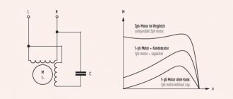
The values of efficiency, power and starting torque for single-phase motors are significantly lower than for three-phase devices of the same size. The overload capacity is also higher for 3-phase motors. Thus, the power of a single-phase mechanism does not exceed 70% of the power of a three-phase mechanism of the same size.
device
Device:
- It actually has 2 phases, but only one of them does the work, which is why the motor is called single-phase.
- Like all electric machines, a single-phase motor consists of 2 parts: stationary (stator) and moving (rotor).
- It is an asynchronous electric motor, the stationary component of which has one working winding, connected to a single-phase alternating current source.
The strengths of this type of engine include the simplicity of the design, which is a rotor with a squirrel-cage winding. The disadvantages are low starting torque and efficiency.
The main disadvantage of single-phase current is its inability to generate a magnetic field that performs rotation. Therefore, a single-phase electric motor will not start on its own when connected to the network.
In the theory of electrical machines, the rule applies: in order for a magnetic field to arise that rotates the rotor, there must be at least 2 windings (phases) on the stator. It is also required to shift one winding by a certain angle relative to the other.
During operation, alternating electric fields flow around the windings:
- In accordance with this, the so-called starting winding is located on the stationary section of the single-phase motor. It is shifted 90 degrees relative to the working winding.
- A current shift can be obtained by including a phase-shifting link in the circuit. Active resistors, inductors and capacitors can be used for this.
- 2212 electrical steel is used as the basis for the stator and rotor.
Advantages of single-phase motor mechanism.
Among the advantages of 1-phase motors, the following are noted:
- simplicity of design;
- durability - with timely maintenance, the engine can last for years;
- reliability;
- efficiency – consumption of a small amount of energy;
- affordable price;
- maintainability - in case of failure, you can easily replace damaged or burnt parts;
- minimal care;
- possibility of operation from a network with a standard voltage of 220 V without energy converters.
Most modern household appliances are equipped with single-phase motors. The reason is explained by their simplicity and low cost. Such motors are used to equip large and small household appliances. In addition, they have found application in the creation of equipment for industrial and manufacturing enterprises.
But are there any disadvantages to a single-phase motor? There are not many of them. Almost all of them are due to the simplicity of the design. So:
- low power factor. For this reason, they are used to create most household appliances;
- high starting current;
- the ability to limit engine speed during network fluctuations.
The main disadvantage is the lack of starting torque. However, for household appliances and simple devices this minus is not significant and does not affect operation.
Asynchronous or collector: how to distinguish
In general, you can distinguish the type of engine by a plate - a nameplate - on which its data and type are written. But this is only if it has not been repaired. After all, anything can be under the casing. So if you are not sure, it is better to determine the type yourself.
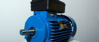
This is what a new single-phase capacitor motor looks like
How do collector motors work?
You can distinguish between asynchronous and commutator motors by their structure. The collectors must have brushes. They are located near the collector. Another mandatory attribute of this type of engine is the presence of a copper drum, divided into sections.
Such motors are produced only as single-phase ones; they are often installed in household appliances, as they allow one to obtain a large number of revolutions at the start and after acceleration. They are also convenient because they easily allow you to change the direction of rotation - you just need to change the polarity. It is also easy to organize a change in the rotation speed by changing the amplitude of the supply voltage or its cutoff angle. That is why such engines are used in most household and construction equipment.
Commutator motor structure
The disadvantages of commutator motors are high operating noise at high speeds. Remember a drill, an angle grinder, a vacuum cleaner, a washing machine, etc. The noise during their operation is decent. At low speeds, commutator motors are not so noisy (washing machine), but not all tools operate in this mode.
The second unpleasant point is that the presence of brushes and constant friction leads to the need for regular maintenance. If the current collector is not cleaned, contamination with graphite (from brushes being worn out) can cause adjacent sections in the drum to become connected and the motor simply stops working.
Online calculation of motor capacitor capacity
Enter data for calculating capacitors - motor power and efficiency
There is a special formula that can be used to calculate the required capacity accurately, but you can easily get by with an online calculator or recommendations that are derived from many experiments:
Capacitors must be non-polar, that is, not electrolytic. The operating voltage of these capacitors must be at least 1.5 times higher than the network voltage, that is, for a 220 V network we take capacitors with an operating voltage of 350 V and higher. To make starting easier, look for a special capacitor in the starting circuit. They have the words Start or Starting in their markings.
Starting capacitors for motors
These capacitors can be selected using the method from smallest to largest. Having thus selected the average capacity, you can gradually add and monitor the operating mode of the engine so that it does not overheat and has enough power on the shaft. Also, the starting capacitor is selected by adding until it starts smoothly without delays.