What is an asynchronous motor?
AC electric motors have found quite wide application in various spheres of our life, in hoisting, processing, and measuring equipment. They are used to convert electrical energy that comes from the network into mechanical energy of a rotating shaft. Most often, asynchronous AC converters are used. In them, the rotation speed of the rotor and stator is different. A structural air gap is provided between these active elements.
Both the stator and the rotor have a rigid core made of electrical steel (composited type, made of plates), acting as a magnetic circuit, as well as a winding that fits into the structural grooves of the core. It is the way in which the rotor winding is organized or laid out that is the key criterion for classifying these machines.
Squirrel-cage motors (SCR)
Here, a winding is used in the form of aluminum, copper or brass rods, which are inserted into the grooves of the core and closed on both sides by disks (rings). The type of connection of these elements depends on the engine power: for small values, the method of joint casting of disks and rods is used, and for large values, separate production is used, followed by welding to each other. The stator winding is connected using delta or star circuits.
Wound rotor motors
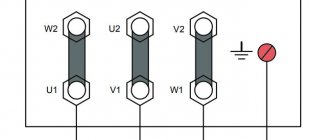
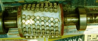
The three-phase rotor winding is connected to the network via slip rings on the main shaft and brushes. The “star” scheme is taken as the basis. The figure below shows a typical design of such an engine.
Smooth start of asynchronous electric motors
In addition to unconditional advantages, ADs have significant disadvantages. This is a jerk at the start and high starting currents, 7 times higher than the rated ones. To soft start the electric motor, the following methods are used:
- switching of windings according to the star-delta circuit;
- turning on the electric motor through an autotransformer;
- use of specialized devices for soft starting.
Most frequency controllers have a soft motor start function. This not only reduces inrush currents, but also reduces the load on the actuators. Therefore, frequency regulation and soft starting are quite closely related.
Operating principle and speed of asynchronous motors
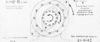
Let's consider this issue using the example of ADKR, as the most common type of electric motors in lifting, transport and processing equipment. The mains voltage is supplied to the stator winding, each of the three phases of which is geometrically displaced by 120°. After applying voltage, a magnetic field arises, which creates, by induction, an emf and a current in the rotor windings. The latter causes electromagnetic forces that cause the rotor to rotate. Another reason why all this happens, namely, EMF occurs, is the difference in the speed of the stator and rotor.
One of the key characteristics of any ADCR is the rotation speed, which can be calculated using the following relationship:
n=60f/p, rpm
where f is the frequency of the mains voltage, Hz, p is the number of stator pole pairs.
All technical characteristics are indicated on a metal plate attached to the body. But if it is missing for some reason, then the number of revolutions must be determined manually using indirect indicators. Typically, three main methods are used:
- Calculation of the number of coils. The obtained value is compared with the current standards for voltage 220 and 380V (see table below),
- Calculation of revolutions taking into account the diametric pitch of the winding. To determine, a formula of the form is used:
where 2p is the number of poles, Z1 is the number of slots in the stator core, y is the actual winding pitch.
Standard speed values:
- Calculation of the number of poles along the stator core. Mathematical formulas are used, which take into account the geometric parameters of the product:
2p = 0.35Z1b/h or 2p = 0.5Di/h,
where 2p is the number of poles, Z1 is the number of slots in the stator, b is the tooth width, cm, h is the back height, cm, Di is the internal diameter formed by the core teeth, cm.
After this, based on the data obtained and magnetic induction, it is necessary to determine the number of turns, which is checked against the motors’ passport data.
How to choose a frequency converter?
If you analyze the prices and functions of frequency converters, you can understand that the price determines the number of built-in functions of the frequency converter. Expensive models have great functionality. But to select a device, it is better to be guided by the required conditions of use.
- Frequency generators come with two types of control: scalar and vector. With scalar control, the device operates at certain values of the output potential difference and frequency; they work in primitive household appliances, for example, fans. With vector control, the current strength is set quite accurately.
- When choosing a device, power parameters play a decisive role. The amount of power expands the scope of use and simplifies maintenance.
- When choosing a device, the operating voltage range of the network is taken into account, which reduces the risk of its failure due to sudden changes in potential difference. If the voltage increases excessively, the network capacitors may explode.
- Frequency is an important factor. Its value is determined by production requirements. The lowest value indicates the possibility of using the speed in the optimal operating mode. To obtain a larger frequency range, frequency generators with vector control are used. In reality, inverters with a frequency range of 10 to 10 Hz are often used.
- A frequency converter that has many different outputs and inputs is convenient to use, but its cost is higher and configuration is more difficult. There are three types of frequency connectors: analog, discrete, digital. Reverse communication of input commands is carried out through analog connectors. Digital terminals input signals from digital type sensors.
- When choosing a frequency converter model, you need to evaluate the control bus. Its characteristics are matched to the inverter circuit, which determines the number of pads. The best choice is a frequency generator with a reserve number of connectors for further modernization of the device.
- Frequency drivers that can withstand heavy overloads (15% higher than the motor power) have preferences when choosing. To avoid making mistakes when purchasing a frequency converter, read the instructions. It contains the main parameters for operating the equipment. If you need a device for maximum loads, then you need to choose a frequency converter that keeps the current at peak operation higher than 10% of the nominal value.
Ways to change engine speed
Adjusting the speed of any three-phase electric motor used in lifting and transport machinery and equipment allows you to achieve the required operating modes accurately and smoothly, which is not always possible, for example, due to mechanical gearboxes. In practice, seven main methods of rotation speed correction are used, which are divided into two key areas:
- Change in the speed of the magnetic field in the stator. Achieved by frequency regulation, switching the number of pole pairs or voltage correction. It should be added that these methods are applicable to electric motors with squirrel-cage rotor,
- Changing the amount of slip. This parameter can be adjusted by using the supply voltage, connecting additional resistance to the electrical circuit of the rotor, using a valve cascade or dual power supply. Used for models with wound rotor.
The most popular methods are voltage and frequency regulation (through the use of converters), as well as changing the number of pole pairs (implemented by organizing an additional winding with switching capability).
Methods for controlling the speed of an IM with a wound rotor
The rotation speed of an IM with a wound rotor is changed by changing the slip. Let's look at the main options and methods.
Changing the supply voltage
This method is also used for IMs with a short-circuit rotor. The asynchronous motor is connected through an autotransformer or LATR. If you reduce the supply voltage, the engine speed will decrease.
But this mode reduces the overload capacity of the engine. This method is used for regulation within a voltage range not higher than the rated voltage, since an increase in the rated voltage will lead to failure of the electric motor.
Active resistance in the rotor circuit
When using this method, a rheostat or a set of high-power constant resistors is connected to the rotor circuit. This device is designed to smoothly increase resistance.
Slip increases in proportion to the increase in resistance, and the rotation speed of the electric motor shaft decreases.
- large range of regulation towards lower rotation speed.
- decrease in efficiency;
- increase in losses;
- deterioration of mechanical characteristics.
Asynchronous valve cascade and dual-fed machines
Changing the operating speed of asynchronous electric motors in these cases is done by changing the slip. In this case, the rotation speed of the electromagnetic field remains unchanged. Voltage is supplied directly to the stator windings. The adjustment occurs through the use of sliding power, which is transformed into the rotor circuit and forms an additional EMF. Such methods are used only in special machines and large industrial devices.
Typical speed controller circuits
There is a wide selection of regulators and frequency converters for asynchronous motors on the market today. However, for the domestic needs of lifting or processing equipment, it is quite possible to calculate and assemble a homemade device on a microcircuit based on thyristors or powerful transistors.
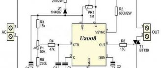
Below is an example of a circuit of a fairly powerful regulator for an asynchronous motor. Due to this, you can achieve smooth control of its operating parameters, reduce energy consumption by up to 50%, and reduce maintenance costs.
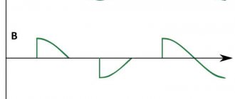
This scheme is complex. For domestic needs, it can be significantly simplified by using a triac, for example, VT138-600, as a working element. In this case, the diagram will look like this:
The motor speed will be regulated by a potentiometer, which determines the phase of the input pulse that opens the triac.
As can be judged from the information presented above, not only its operating parameters, but also the efficiency of the powered lifting or processing equipment depend on the speed of an asynchronous motor. Today you can purchase a wide variety of regulators in the retail chain, but you can also make calculations and assemble an effective device with your own hands.
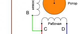
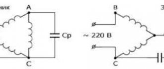
Single-phase asynchronous motors are powered from a conventional 220 V alternating voltage network.
The most common design of such motors contains two (or more) windings - working and phase-shifting. The working one is fed directly, and the additional one is fed through a capacitor, which shifts the phase by 90 degrees, which creates a rotating magnetic field. Therefore, such motors are also called two-phase or capacitor motors.
It is necessary to regulate the rotation speed of such motors, for example, for:
- changes in air flow in the ventilation system
- pump performance control
- changes in the speed of moving parts, for example in machine tools, conveyors
In ventilation systems, this allows you to save energy, reduce the level of acoustic noise of the installation, and set the required performance.
Methods of regulation
We will not consider mechanical methods of changing the rotation speed, for example gearboxes, couplings, gear transmissions. We will also not touch upon the method of changing the number of poles of the windings.
Let's consider methods with changing electrical parameters:
- change in motor supply voltage
- change in supply voltage frequency
Regulating the number of plus pairs of an asynchronous drive
Suitable for asynchronous motors with high speed and complex winding, which helps to change the positive pairs. Engine speeds can be different; we will consider the control principle on an engine with two speeds.
In such a device, all phases contain two half windings. The rotation varies depending on the way they are connected to the motor.
In four-speed motors, the windings look like disparate parts. When the number of pairs changes, the speed of revolutions is reduced by half. The second winding will operate on the same principle.
The critical moment changes with the number of pairs. To keep it from changing, you need to control the voltage simultaneously with changing the number of pairs (switching star-delta or other options can help).
The advantages of this option are the high efficiency and unchanged engine characteristics.
The disadvantage is expressed in stepwise regulation, the large weight of the devices, and the electric motor will cost much more.
Voltage regulation
Speed control in this way is associated with a change in the so-called engine slip - the difference between the rotation speed of the magnetic field created by the stationary engine stator and its moving rotor:
n1— magnetic field rotation speed
n2 — rotor rotation speed
In this case, sliding energy is necessarily released - which causes the motor windings to heat up more.
This method has a small control range, approximately 2:1, and can also only be carried out downwards - that is, by reducing the supply voltage.
How to maintain frequency converters?
For long-term operation of the inverter, it is necessary to monitor its condition and follow the maintenance instructions:
- Clean internal elements from dust. You can use a compressor to remove dust with compressed air. A vacuum cleaner is not suitable for these purposes.
- Periodically monitor the condition of the components and replace them. The service life of electrolytic capacitors is five years, fuse links are ten years. Cooling fans last 3 years before replacement. The wire loops have been used for six years.
- Monitoring the DC bus voltage and the temperature of the mechanisms is a necessary measure. At elevated temperatures, the thermal conductive paste dries out and damages the capacitors. Every 3 years, a layer of conductive paste is applied to the power terminals.
- The operating conditions and operating hours must be strictly observed. The ambient temperature should not exceed 40 degrees. Dust and humidity negatively affect the condition of the working elements of the device.
Frequency regulation
Just recently (10 years ago), there were a limited number of frequency controllers for motor speeds on the market, and they were quite expensive. The reason was that there were no cheap high-voltage power transistors and modules.
But developments in the field of solid-state electronics have made it possible to bring power IGBT modules to the market. As a consequence, there is a massive appearance on the market of inverter air conditioners, welding inverters, and frequency converters.
At the moment, frequency conversion is the main way to regulate the power, performance, speed of all devices and mechanisms driven by an electric motor.
However, frequency converters are designed to control three-phase electric motors.
Single-phase motors can be controlled by:
- specialized single-phase inverters
- three-phase inverters with the exception of the capacitor
Converters for single-phase motors
Currently, only one manufacturer announces serial production of a specialized inverter for capacitor motors - INVERTEK DRIVES.
Optidrive E2 model
For stable engine starting and operation, special algorithms are used.
In this case, frequency adjustment is possible upward, but in a limited frequency range, this is prevented by a capacitor installed in the phase-shifting winding circuit, since its resistance directly depends on the frequency of the current:
f - current frequency
C - capacitance of the capacitor
The output stage uses a bridge circuit with four output IGBT transistors:
Optidrive E2 allows you to control the motor without removing the capacitor from the circuit, that is, without changing the motor design - in some models this is quite difficult to do.
Advantages of a specialized frequency converter:
- intelligent motor control
- Stably stable engine operation
- the enormous capabilities of modern inverters: the ability to control the operation of the motor to maintain certain characteristics (water pressure, air flow, speed under changing load)
- numerous protections (motor and device itself)
- sensor inputs (digital and analogue)
- various outputs
- communication interface (for control, monitoring)
- preset speeds
- PID controller
Disadvantages of using a single-phase inverter:
Soft start
AD has its downsides. For example, the start starts too abruptly, which can lead to breakdown if the starting current exceeds the voltage value.
To get started more slowly, there are different options:
- windings are switched according to the star-delta principle;
- you can start working through an automatic transformer;
- special devices are used for launching.
Today, many frequency regulators have the ability to start spinning slowly. The starting current will decrease along with the total load on the IM. Frequency and onset are closely related to each other.
Types of adjustment
There are quite a few options for adjusting the speed. Here are the main ones:
- Power supply with adjustable output voltage.
- Factory adjustment devices that initially come with the electric motor.
- Push-button regulators and standard regulators that simply limit the voltage.
These types of adjustments are bad because as the voltage decreases or increases, the power also drops. In some power tools this is acceptable, but, as practice shows, in most cases this is unacceptable due to a strong drop in power and, accordingly, efficiency.
The most acceptable option would be a regulator based on a triac or thyristor. Not only does such a regulator not reduce power when the voltage decreases, it also allows for smoother starting and speed control. In addition, such a scheme can be made with your own hands. Below is a picture of the speed control with power maintenance. The circuit is assembled on the basis of a BTA 41,800 V triac.
All ratings of electrical elements are indicated in the diagram. This is the circuit after assembly, it works quite stably and provides smooth adjustment of the brushed motor. When the output voltage decreases, the power does not decrease, which is a significant plus.
If desired, you can assemble the speed controller of a 220 V brushed motor with your own hands. This circuit is assembled on the basis of a VTA26-600 triac, which must first be installed on a radiator, since this element gets quite hot under load.
The diagram looks like this.
It can successfully cope with the adjustment of power tools such as a drill, grinder, circular saw, and jigsaw. If desired, you can use the circuit as a power regulator for heating elements, heaters, and as a dimmer. The disadvantages include the impossibility of adjusting the power of devices powered by direct current.
https://youtube.com/watch?v=vVeR4jVfTIg
DIY making
If there is no opportunity or desire to purchase a factory-type regulator, then you can assemble it yourself. Although regulators of the "tda1085" type have proven themselves very well. To do this, you need to familiarize yourself with the theory in detail and start practicing. Triac circuits are very popular, in particular the speed controller of a 220V asynchronous motor (diagram 5). It's not difficult to make. It is assembled using a VT138 triac, which is well suited for these purposes.
Scheme 5 - Simple speed controller on a triac.
This regulator can also be used to adjust the speed of a 12-volt DC motor, as it is quite simple and universal. The speed is regulated by changing the parameters P1, which determines the phase of the incoming signal, which opens the transition of the triac.
The operating principle is simple. When the engine starts, it slows down, the inductance changes downward and contributes to an increase in U in the “R2—>P1—>C2” circuit. When C2 is discharged, the triac opens for some time.
There is another scheme. It works a little differently: by providing a reverse type of energy flow, which is optimally beneficial. The circuit includes a fairly powerful thyristor.
Scheme 6 - Design of a thyristor regulator.
The circuit consists of a control signal generator, an amplifier, a thyristor and a circuit section that functions as a rotor rotation stabilizer.
The most universal circuit is a regulator based on a triac and dinistor (scheme 7). It is able to smoothly reduce the shaft rotation speed, reverse the motor (change the direction of rotation) and reduce the starting current.
Read also: Scheme of resistance spot welding
The principle of operation of the circuit:
- C1 is charged until U breakdown of dinistor D1 through R2.
- When D1 breaks, it opens the junction of triac D2, which is responsible for controlling the load.
The load voltage is directly proportional to the frequency component when D2 opens, which depends on R2. The circuit is used in vacuum cleaners. It contains universal electronic control, as well as the ability to easily connect 380 V power. All parts should be placed on a printed circuit board made using laser-iron technology (LUT). You can find out more about this board manufacturing technology on the Internet.
Thus, when choosing an electric motor speed controller, you can buy a factory one or make it yourself. Making a homemade regulator is quite simple, since if you understand the principle of operation of the device, you can easily assemble it. In addition, you should follow safety rules when installing parts and when working with electricity.
Commutator motors can often be found in household electrical appliances and power tools: washing machine, grinder, drill, vacuum cleaner, etc. Which is not at all surprising, because commutator motors allow you to obtain both high speeds and high torque (including high starting torque ) - which is what you need for most power tools.
In this case, commutator motors can be powered by both direct current (in particular, rectified) and alternating current from a household network. To control the rotor speed of a commutator motor, speed controllers are used, which will be discussed in this article.
First, let's remember the design and principle of operation of a commutator motor. The commutator motor necessarily includes the following parts: rotor, stator and brush-collector switching unit. When power is applied to the stator and rotor, their magnetic fields begin to interact and the rotor eventually begins to rotate.
Power is supplied to the rotor through graphite brushes that fit tightly to the commutator (to the commutator lamellas). To change the direction of rotation of the rotor, it is necessary to change the phasing of the voltage on the stator or on the rotor.
The rotor and stator windings can be powered from different sources or can be connected in parallel or in series with each other. This is how commutator motors of parallel and series excitation differ. It is the series-excited commutator motors that can be found in most household electrical appliances, since such inclusion makes it possible to obtain a motor that is resistant to overloads.
Speaking about speed controllers, first of all we will focus on the simplest thyristor (triac) circuit (see below). This solution is used in vacuum cleaners, washing machines, grinders, and shows high reliability when operating in alternating current circuits (especially from a household network).
This circuit works quite simply: at each period of the mains voltage, the capacitor is charged through a resistor to the unlocking voltage of the dinistor connected to the control electrode of the main switch (triac), after which the triac opens and passes current to the load (to the commutator motor).
By adjusting the charging time of the capacitor in the triac opening control circuit, the average power supplied to the engine is regulated, and the speed is adjusted accordingly. This is the simplest regulator without current feedback.
The triac circuit is similar to a regular dimmer for adjusting the brightness of incandescent lamps; there is no feedback in it. To provide current feedback, for example to maintain acceptable power and avoid overloads, additional electronics are required. But if we consider the options from simple and straightforward circuits, then the triac circuit is followed by a rheostat circuit.
The rheostat circuit allows you to effectively regulate speed, but leads to the dissipation of a large amount of heat. This requires a radiator and effective heat removal, which means energy loss and low efficiency as a result.
Regulator circuits based on special thyristor control circuits or at least on an integrated timer are more effective. Switching of the load (commutator motor) on alternating current is carried out by a power transistor (or thyristor), which opens and closes one or more times during each period of the network sinusoid. This regulates the average power supplied to the engine.
The control circuit is powered by 12 volts DC from its own source or from a 220 volt network through a quenching circuit. Such circuits are suitable for controlling powerful motors.
The principle of regulation with DC microcircuits is, of course, PWM - pulse width modulation. A transistor, for example, opens with a strictly specified frequency of several kilohertz, but the duration of the open state is regulated. So, by rotating the handle of the variable resistor, the rotation speed of the rotor of the commutator motor is set. This method is convenient for maintaining low speeds of a commutator motor under load.
Better control is direct current regulation. When PWM operates at a frequency of about 15 kHz, adjusting the pulse width controls the voltage at approximately the same current. Let's say, by adjusting the constant voltage in the range from 10 to 30 volts, they get different speeds at a current of about 80 amperes, achieving the required average power.
Speed controller for commutator motor on TDA1085:
If you want to make a simple regulator for a commutator motor with your own hands without any special requests for feedback, then you can choose a thyristor circuit. All you need is a soldering iron, a capacitor, a dinistor, a thyristor, a pair of resistors and wires.
If you need a higher-quality regulator with the ability to maintain stable speeds under dynamic loads, take a closer look at regulators on microcircuits with feedback that can process the signal from the tachogenerator (speed sensor) of a commutator motor, as is implemented, for example, in washing machines.