5.
6.
SENSORS FOR MEASURING ENGINE ROTOR ROTATION SPEED
5.1
Purpose and classification
Based on the shaft rotation speed, the dynamic and thermal stress of the engine can be determined. Engine thrust is a function of rotation speed, so speed can be used to indirectly judge thrust.
IU,
Designed to measure the angular speed of rotation of an aircraft engine shaft, they are called
tachometers.
They are electromechanical sensors that convert mechanical rotational motion directly into an electrical signal. Thus, unlike parametric sensors (potentiometric, inductive, capacitive), tachometers are generator-type sensors.
Tachometers with an electrical output signal (tachogenerators) are used on aircraft to measure the speed of rotation of the turbine shaft of a turbojet engine (up to 20,000 rpm
), angular speed of rotation of the crankshaft of piston aircraft engines (up to
4000 rpm
). In addition, tachogenerators are used as feedback sensors in autopilots and various tracking systems, where they measure the angular velocity of rotation of the executive bodies. Sometimes linear velocity is measured instead of angular velocity, such as the linear velocity of a hydraulic servo rod.
To design tachometers, you can use any physical phenomenon in which the rotation speed is related by a certain relationship to some easily determined value.
Classifying tachometers according to the principle of operation of the sensing element, we can note the following types that have become widespread:
1) centrifugal, in which the sensitive element reacts to the centrifugal force developed by unbalanced masses during shaft rotation;
2) magnetic induction, based on the dependence of eddy currents induced in a metal body on the rotation speed;
3) electrical direct and alternating current, based on the dependence of e. d. s generated in a conductor rotating in a magnetic field, depending on the rotation speed.
Based on the type of current, tachometers are divided into direct and alternating current tachometers.
According to the method of excitation, DC tachometers are divided into:
— magnetoelectric, the excitation of which is carried out using permanent magnets;
— electrodynamic, having an excitation winding with an independent power source.
5.2
Methods for measuring the angular speed of rotation of the motor shaft
There are the following main methods for measuring the angular speed of rotation of the motor shaft:
1)
centrifugal method, based on the dependence of centrifugal forces on the angular velocity of rotation of the inertial mass;
2)
hourly method, based on the dependence of the angle of rotation of the shaft for a fixed period of time on the angular speed of its rotation;
3)
friction method, based on self-alignment (due to sliding friction) of the peripheral speed of rotation of the friction roller with the peripheral speed of a cone rotating at a constant angular speed;
4)
magnetic induction method, based on the entrainment of a conducting body (cylinder, disk, etc.) by the field of a rotating permanent magnet due to the interaction of induced currents induced in the conducting body with the magnetic field of a permanent magnet;
5)
induction method based on the dependence of the emf induced by the field of a permanent magnet in the winding on the angular speed of rotation of the magnet or winding. Depending on the circuit, they can produce signals using direct or alternating current;;
6)
pulse method, based on determining the frequency of electrical pulses generated using a contact or non-contact (photoelectric, inductive, capacitive, etc.) breaker or switch connected to a shaft, the rotation speed of which is controlled;
7)
stroboscopic method, based on the phenomenon of apparent immobility of a rotating body when it is periodically observed for short periods of time with a frequency equal to or a multiple of the rotation frequency;
differentiation method based on differentiation of the position sensor signal (potentiometric, inductive, etc.).
One of the main requirements for aircraft tachometers is the requirement for their distance (see below). To build remote tachometers on aircraft
The magnetic induction method is mainly used due to its simplicity and the linear dependence of the instrument reading on the angular velocity.
Direct and alternating current tachogenerators based on the inductive method are used as sensors for automatic control systems and tracking systems.
In devices with a limited amount of shaft movement, electrical differentiation circuits are sometimes used.
Pulse methods have some promise, especially in connection with the development of digital computers.
Centrifugal, clockwise, frictional and stroboscopic methods for measuring the angular velocity of shaft rotation have not been developed on aircraft
for one reason or another (bulkiness, installation inconvenience, difficulty in automating measurements, nonlinearity of characteristics, increased errors, etc.).
5.3
Requirements for tachometers
Errors in measuring rotation speed should not exceed ±1% in piston engines,
and in gas turbine engines
± 0.5%.
Aviation tachometers must be remote. Electric tachometers of direct and alternating current satisfy this requirement. Magnetic induction tachometers become remote only when using an electric shaft. Centrifugal tachometers are non-remote, but they develop a large adjustment force, therefore they are used as a sensor for rotation speed controllers (RPR)
.
the TE type (TE-5-2, TE-15, 2TE-15-1, TE-10-48) are widely used in aviation
etc.) with a scale graduated in
rpm
and ITE type
(ITE-1, ITE-2, ITE-21,
etc.) with a scale graduated in
percentage
.
Since there is no fundamental difference between these types of devices, we will consider a tachometer with a percentage scale ITE-1.
The sensor for measuring the speed of the latter is a sensor of
the DTE-1(2) type.
Various methods for measuring shaft rotation speed are known, but the magnetic induction method has found its main application in aircraft tachometers.
5.4
Magnetic induction tachometers
Two versions of magnetic induction tachometers are used - with a cylindrical sensitive element and with a disk one.
The operating principle of magnetic induction tachometers is based on the phenomenon of inducing eddy currents in a metal body rotating in a magnetic field. The interaction of eddy currents with the magnetic field that caused them is used to activate the pointing system of the device.
| The main part of the tachometer is the measuring unit, which consists of permanent magnets and a sensing element in the form of a hollow cylinder (Fig. 5.4.1, a) or disk (rice. 5.4.1, b). Typically, a permanent magnet rotates at a measurable speed, and the sensing element, made of a metal with a large and slightly temperature-dependent electrical resistivity, is kept from rotating by a spiral spring. Magnetic induction tachometers are distinguished by their uniform scale, large range of measured speeds, low weight and dimensions. The disadvantages of these tachometers include the lack of distance and the dependence of their readings on the ambient temperature. Features of the design of magnetic induction tachometers.
|
Instruments for measuring rotation speed
Depending on the installation location of the tachometer and the method of use, tachometers are divided into stationary, remote and manual. According to the principle of operation, there are mechanical (centrifugal), magnetic, magnetic induction, electric and electronic tachometers.
The principle of operation of mechanical tachometers is based on the use of centrifugal forces, proportional to the square of the angular velocity, acting on centrifugal divergent loads (inclined ring) located on the shaft and rotating with it around an axis (Fig. 1, a). The sensitive element is ring 1 on axis 2 passing through drive roller 3. The ring is loaded by a spiral spring 4 and is connected by a rod 5 to a movable coupling 6. When the roller rotates, the ring tends to take a position perpendicular to the axis of rotation. The clutch, through the intermediate ring 9 and the rack 7, engages with the gear 10, on the axis of which an arrow 8 is attached, moving along the instrument scale (graduated in rpm). The tachometer is fixed motionless, and shaft 3 is driven into rotation through a transmission from the engine shaft.
In steady state, the centrifugal force acting on the rotating ring 1 is balanced by the force of the spiral spring, and the tachometer needle is stationary. When the shaft rotation speed changes, the balance of forces is disrupted, causing the ring to rotate relative to axis 2 by an angle α and a corresponding rotation of the arrow 8 of the device. Mechanical centrifugal measuring instruments
have a nonlinear static characteristic, so their scale is uneven.
Periodic monitoring of the rotation speed and checking of stationary tachometers is carried out with a mechanical centrifugal manual tachometer (Fig. 1, b), pressing tip 1 to the end of the rotating shaft. Housing 2 has a built-in gearbox with a switching device that allows you to change the gear ratio from tip 1 to the sensing element for measurement in five speed ranges from 25 to 10,000 rpm. The gearbox is switched and pointer 3 is set by moving along the axis of the drive shaft tip with button 4 pressed. Depending on the set rotation speed range, the instrument readings are determined on one of two scales.
The advantages of mechanical tachometers include high accuracy of readings, but the disadvantages are the impossibility of remote reading.
The magnetic induction tachometer has a uniform scale. In the tachometer (Fig. 2.), rotation from drive shaft 1 through bevel gears and shaft 2 is transmitted to a rotor with permanent magnets 3, between which there is an aluminum disk 4 on axis 10.
Under the influence of the rotating field of magnets, an electric current is induced in the disk, creating its own magnetic field. The force of interaction of the magnetic fields is balanced by the force of the hair spring 5, one end of which is fixed to the axis 10, and the other in the body of the device.
Proportional to the speed of rotation of the drive shaft 1, the acting forces change, the rotation of the disk 4, the axis 10 and the arrow 7 rigidly connected to it along the scale 8.
A magnetic induction damper is mounted in the device, consisting of an aluminum disk 9 mounted on a shaft 10 and a stationary system with permanent magnets 6. When moving, a current is induced in the disk 9 and a magnetic field is created that interacts with the field of permanent magnets. And since the force of interaction of these fields is directed in the direction opposite to the movement of the disk, the oscillations of the instrument needle occur.
Remote magnetic induction tachometers
Remote measurement of rotation speed is based on the principle of electrically remote transmission of rotation of the engine shaft to the shaft of the magnetic induction measuring unit of the meter and conversion of the shaft rotation speed into angular movements of the meter needle.
The tachometer works as follows (Fig. 3): in the stator winding 11 of the sensor, when the rotor 15 rotates, a three-phase current is excited with a frequency proportional to the speed of the engine shaft. The current through three wires is driven to the stator winding 12 of the synchronous servomotor.
The rotation frequency of the magnetic field of the meter stator is proportional to the frequency of the currents in the phase windings. The rotor of the meter motor rotates at a frequency synchronous with the rotation of the stator magnetic field. At the end of the motor rotor shaft there is a magnetic assembly 2 with six pairs of permanent magnets, between the poles of which a sensitive element 8 is located. When the magnetic assembly rotates, eddy currents are induced in the sensitive element. As a result of the interaction of eddy currents with the magnetic field of the magnetic assembly, a torque of the sensitive element is created. The torque of the sensing element is counteracted by a spiral spring 7, one end of which is fixed on the axis of the sensing element, the other is stationary. Since the moment of the spiral spring is proportional to the angle of its twist, the angle of rotation of the sensing element is proportional to the rotation speed of the magnetic assembly, and corresponds to the rotation speed of the motor shaft. At the other end of the axis of the sensitive element there is an arrow 5, indicating the engine shaft rotation speed on a uniform scale 4 of the meter.
To increase the stability of the needle and improve the reading of the device, damping of the moving system of the meter is applied. When the moving system moves, the magnetic flux of the magnet 6 induces eddy currents in the aluminum disk 3, which interact with the magnetic field of the magnets, and a braking torque occurs in the moving system. The rotor consists of two permanent magnets 13 and three hysteresis disks 14 connected together. The interaction of the rotor with the magnetic field of the stator is determined by the interaction of the magnetic fields of the permanent magnets of the stator and hysteresis disks.
Operating principle of magnetic tachometers
The operation of a magnetic tachometer is based on the phenomenon of induction of eddy currents (Foucault currents) in a non-magnetic disk by a rotating constant field. In its normal state, an aluminum or copper disk does not have magnetic properties, but if you place it in a rotating magnetic field, eddy currents arise in it. These currents interact with the magnetic field, so the non-magnetic disk also begins to rotate after the magnet.
To operate the tachometer, an arrow is attached to the disk, on the shaft of which a return spring is attached. The magnet is connected to the crankshaft or one of the transmission shafts via a flexible shaft. The higher the engine speed, the faster the magnet rotates, and the higher the force deflecting the non-magnetic disk fixed by the spring - all this is reflected in the position of the arrow.
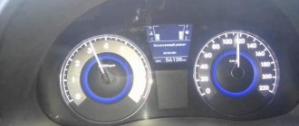
EVERYTHING about the tachometer: what it is, types, what it measures, principle of operation and device, what it is needed for
A car tachometer is a special measuring device that allows you to set the rotation speed of moving parts in car mechanisms. The measurement principle is based on calculating the number of revolutions that the crankshaft of an internal combustion engine makes in one minute.
The electronic device can operate on all types of transport. The devices are installed to measure speed on railway vehicles, tractors, combines, conventional cars, sea ships and airplanes - various equipment equipped with an internal combustion engine.
In this article I will tell you in simple terms about the tachometer, what it is, what it measures, what types exist, how it works and what it consists of, how to use the device correctly. I promise it will be interesting!
Operating principle of electric tachometers
Electric tachometers use electrical signals or individual pulses to measure. Electrical signals proportional to the crankshaft speed in a gasoline engine are generated by the ignition system and an electric generator, and in a gasoline engine only by the generator. The necessary signal can also be received from the electronic engine control unit.
The simplest way to operate is a tachometer connected to an electric generator. The generator is driven from the crankshaft via a V-belt drive, so the generator rotor speed is always proportional to engine speed. And the magnitude of the EMF generated on the winding depends on the rotation speed of the generator rotor, which is used to connect an electric machine tachometer. In essence, the device is a voltmeter that measures the voltage on the generator and converts it into crankshaft speed readings. The tachometer is connected to the generator through a special connector, which requires adjustment of the device to the specific generator.
What it is?
What is this in the car? A tachometer is a special measuring device designed to determine the rotation speed of various elements. This indicator is located on the instrument panel next to the speedometer.
The tachometer was invented by American engineer Curtis Widder in 1903, after he invented the cyclometer - a device for reading the mileage of a bicycle. He even had his own slogan: “It’s nice to know how far you’ve traveled.” By the way, a similar device was described in 23 BC. historian Vitruvius. A similar device for measuring distance was invented by the Chinese scientist Zhang Chen two thousand years ago.
What does this necessary device measure? The device allows you to determine the number of scrolls performed per unit of time. The result obtained depends on the intensity of rotation of the rotors, shaft, disk in different machines, mechanisms and units. It is difficult to immediately understand what it does, what it looks like, where it is located and what the device shows.
How to check engine speed with a multimeter video
Subscribe to a topic
Notification by e-mail about replies to a topic during your absence from the forum.
Subscribe to this forum
Notification by e-mail about new topics on the forum during your absence from the forum.
Download/Print theme
Download the theme in various formats or view a printable version of the theme.
This time we’ll tell you how and why you need to check your car with a multimeter before buying. The methods can be used directly when meeting with the seller and inspecting the car. To make things go faster, practice the day before in a friend’s or acquaintance’s car.
First of all, you need a multimeter in order to notice a current leak on the machine in time. Because of this, the engine may run unevenly and the emissions will become more smelly. The wiring may short out, which will damage the radio, electronic control unit and other devices. Or the iron horse simply won’t start.
Content
How to check current leakage on a used car with a multimeter
The check includes:
- Turn off the engine, remove the key. Close the doors, but open the windows - the battery will not work continuously, and the car may be locked with a central lock.
- Make sure that the additional lighting and radio are turned off.
- Remove the negative terminal from the battery.
- Place one probe between the negative terminal and the negative terminal of the battery - the device will show the leakage current value.
The normal value is 15-70 mA. If the numbers are higher and you and the seller have time, try to find the reason. To do this, also connect a multimeter, then start removing the relays and fuses one by one.
The readings have returned to normal - you have found the cause of the current leak. Perhaps further repair or replacement of a part, or even the entire wiring, will be required. You can confidently ask the car seller for a discount or refuse the purchase altogether.
There may be several reasons for the leak. The following may be involved:
- battery;
- sensors;
- high voltage wires;
- generator.
Each element can be checked using a multimeter.
How to test a car battery with a multimeter
Testing a car battery with a multimeter involves connecting two probes at once. Also turn off the engine before taking measurements.
Place the red probe against the “positive” terminal, the black one against the “negative” terminal. If you mix it up, don’t worry, the device will show the current numbers, just with a minus sign.
Look at the device screen. The normal battery charge ranges from 12.6 to 12.9 volts.
The operation of the battery can also be checked with the engine running. When checking the car battery with a multimeter, you will also find out how the battery works in conjunction with the generator, as well as whether the voltage regulator is working properly.
Normal numbers with the engine running are 13-14 volts. If the multimeter shows less, the battery needs to be charged, or there is a current leak.
Remember: a multimeter will show the battery charge, but will not tell you everything about its operation. There are other devices for this. For example, a load fork.
How to check car sensors with a multimeter
The reason for the “death” of the battery, voltage surges, and unnecessary values on the instrument panel can be various sensors in the car. According to the experience of motorists, 5 types of sensors most often cause problems:
You can understand where they are located from the instructions for the car, on car enthusiast websites, and various forums.
To check your car's sensors with a multimeter, you will also need information about the normal voltage readings specifically for your car. It can also be found in the instructions or on the Internet.
ABS sensor
It is checked by two parameters: voltage and resistance.
To start measuring, select the appropriate mode on the multimeter. If you want to know the resistance value, for most the norm is 1.2-1.8 kOhm. Connect the device to the sensor and start taking measurements. At the same time, shake the wires going to the element. If the numbers on the screen change and become higher or lower than normal, there is a problem with the sensor.
Measuring voltage is a little more difficult - this can only be done with a jack or in a car service on a stand. You need to spin the car wheel to 40-50 rpm and monitor the multimeter readings. On any machine it should output 2 volts.
Crankshaft sensor
An important element - without it, the car will not start at all, or you will not be able to drive it. If visually it seems to be working, take a multimeter. Connect the device to the sensor and measure the resistance. The norm is usually from 550 to 750 ohms. But be sure to check if these numbers are accurate for the car you're looking at.
Oxygen sensor
Determines whether oxygen remains in the exhaust gases. Before taking measurements, also inspect it - it may be damaged and a multimeter will not be needed at all. Then the element just needs to be replaced.
If everything is in order, measure the voltage and resistance as with the ABS sensor. The algorithm is the same. Start the car and watch the device. After start-up, the numbers 0.1-02 volts will appear on the screen. When the car warms up, the device will show up to 0.9 volts. If you didn’t notice that the indicator has changed, the sensor is most likely faulty.
If the voltage test is successful, find out the resistance readings. The norm ranges from 10 to 40 ohms.
Knock sensor
Determines the shock wave during fuel combustion. The resistance indicators for each car are individual - look for information in different sources.
It's a little easier with tension. First remove the sensor. Connect the plus probe to the signal wire, the negative probe to ground, closer to the mounting bolt. Next comes the fun part - hit the sensor against a wall, chair or table. This is the only way the multimeter will record the voltage reading. The norm on most cars is from 30 to 40 millivolts.
Speed sensor
Be sure to inspect the element before taking measurements. Perhaps it simply oxidized or melted.
Then connect the multimeter and measure. The procedure is the same as with the knock sensor.
The only thing is that they don’t need to hit anything. You can simply rotate or shake. If the multimeter does not show voltage at all, the sensor is faulty.
How to check high-voltage wires on a car with a multimeter
If you feel a loss of car power, see increased fuel consumption, the car shakes, and the idle speed fluctuates, it’s time to check the high-voltage wires. More precisely, measure the resistance in them. Remember the procedure:
- disconnect the wires from the machine or disconnect one wire on both sides;
- turn the device into ohmmeter mode and place the probes on both sides of the wire.
The normal resistance value is 6-10 kOhm. If the device shows less, down to zero, do not be alarmed. The multimeter numbers are influenced by many factors, for example:
- quality of wire insulation;
- length;
- presence of microdamages;
- wire type.
If your car's performance is outside the normal range, it is better to contact a car service center, where the resistance will be measured with professional and more accurate instruments.
How to check a generator on a car with a multimeter
Checking the generator is similar to measuring other elements of the car that cause current leakage.
- Traditionally, turn off the ignition, take out the key, turn off the radio, and so on.
- Connect the multimeter to the battery.
- Measure the voltage. A fully charged battery will produce between 12.5 and 12.9 volts.
- After this, start the engine, turn on the heated windows, seats, heater, and low beam.
And measure the voltage again. The norm is 13-14 volts. Maximum - 14.8 volts. In these cases, the generator works like a clock. If the multimeter shows lower numbers, the generator is not charging the battery. So, get ready to pay a decent amount for replacing or repairing the unit.
What does the tachometer measure in a car?
The purpose of the device allows you to use the resources of the car engine without consequences - that’s what the device is used for. The tachometer greatly helps reduce wear on engine parts. Each engine has individual technical characteristics that determine its final performance. These parameters depend on the maximum permissible torque and maximum power, adjusted for speed. A tachometer is a device for measuring the listed parameters.
Thus, the main function is to provide the driver with data on the basis of which the number of rotations can be monitored and the gear used (lower or higher) can be changed in a timely manner. This applies to vehicles with manual transmission.
Here are some examples of the usefulness of a tachometer:
- If the engine constantly operates at low speeds (up to 2000 rpm) , then fuel consumption will be low, but some problems may occur. If you abruptly engage a high gear, the internal combustion engine will begin to work under high load. The combustible mixture will not burn completely and as a result, carbon deposits will form on the cylinders, pistons and spark plugs. And when operating at low speeds, poor lubrication of the unit components with oil occurs, as a result of which their wear increases.
- If the engine constantly operates at high speeds (over 4000 rpm) , this will greatly increase gasoline consumption. The engine will overheat, its components will wear out faster, and the oil will quickly lose its performance properties.
Is it necessary to purchase a tachometer and how to choose the right device
This is not to say that a tachometer is a mandatory element in a car. But one cannot deny its importance and usefulness. The measuring device helps:
When choosing a device, you need to consider many factors. For example, electronic models are developed for engines with different numbers of cylinders (information can be found in the technical specifications). By installing the device in a car with the wrong number of cylinders, you can get unreliable information. Before purchasing the device you must:
- Study its technical characteristics;
- Check with specialists whether a specific model is suitable for the car brand;
- Take into account the engine (petrol and diesel devices read information differently).
The tachometer is installed according to the size and design. Installation is possible using brackets, instead of any other equipment on the panel, and even using double-sided tape. It's still worth buying a tachometer. It will help in solving many questions regarding cars, especially for beginners. Ask any questions you have in the comments, and we will be happy to help you!
Tips for choosing a shaft speed meter
- The device used to measure the shaft rotation speed (or the so-called angular velocity) is called a tachometer. If the device is additionally equipped with recording and recording modules, then it will be a tachograph. The device for summing the number of shaft revolutions is also called a counter.
Tachometers are used wherever it is necessary to control the shaft speed in all kinds of engines - in vehicles, conveyor units, pumping stations, etc. Tachometers are often used to monitor the operation of machine tools. The scope of use, in a word, is quite extensive.
Types and types of tachometers
Tachometers used in transport are divided into several types according to the principle of operation, the method of signal processing and indication, the method of connection and applicability.
According to the principle of operation and method of connection, tachometers are:
- Mechanical/electromechanical (centrifugal, magnetic) with direct drive;
- Electric with connection to the engine ignition system - electronic (pulse);
- Electric with connection to an electric generator - electric machine.
According to the method of signal processing, tachometers are either analog or digital.
According to their applicability, tachometers are divided into several groups:
- For gasoline engines with contact and non-contact ignition systems - connection directly to the primary (low-voltage) circuit;
- For all types of engines with an electronic control unit - connection to the ECU, the unit itself uses signals from the ignition system or the crankshaft position sensor to control the tachometer;
- For diesel engines - connection to a generator.
As a rule, tachometers are manufactured for use on certain brands and models of cars, tractors and other equipment; some devices can be used on various vehicles equipped with the same engines, ignition systems, etc.
Types of shaft speed meters
There are different types of tachometers - depending on the installation location and use cases, for example, they differ:
stationary;
The principle of operation is:
- centrifugal mechanical devices;
- magnetic type;
- magnetic induction;
- electrical and electronic.
Mechanical ones are simpler in design, but electronic ones can offer greater measurement accuracy and a wide range of settings. There are also combined models that use several measurement principles at once. For example, contact mechanical and contactless electronic.
How many revolutions per minute does a car wheel make?
The easiest way to understand that the tire pressure is incorrect is to monitor the behavior of the car. A stiffer ride than usual, when every bump and hole is felt, and low brake sensitivity indicate that the wheels are overinflated.
How many revolutions does the wheel make at a speed of 100 km/h?
There is a path, the number of revolutions
There is.
If he travels 100 km
in one hour, then 7500 divided by six. approximately 1200 rpm.
- How to adjust the carburetor on a chainsaw
- How to work with a level
- What a manual wood router can do
- Why does the saw cut crookedly?
- What is torque
- How much does a Yamz 238 engine weigh?
- Man how many horsepower
- How does a clutch work in a car?
- How to sharpen a chainsaw chain
How many revolutions per minute does a car wheel make?
For one revolution of the wheel the machine
travels L kilometers.
This means that in order for the car
to travel 1 kilometer,
the wheel
must make 1/L
revolutions
.
At a speed of V km/h, the wheel
will make V/L
revolutions
per hour or V/(L*60)
revolutions per minute
(rpm).
How to calculate the speed of rotation of a wheel?
These and many other questions can be answered using this calculation. To do this, you need to divide the rotation
engine shaft to the gear ratio of the current gear.
Divide the resulting result by the final drive gear ratio - the result is the speed of rotation
drive
wheels
.
How to find out the number of wheel revolutions?
The equation of uniform rotational motion can be represented as follows: N = nt, where N is in revolutions
, n - rpm and t - in min.
We find the number of revolutions
of the flywheel: N = 152.8 ∙ 5 = 764 revolutions.
How to convert revolutions per minute to kilometers per hour?
That is, to convert m/min to km/ h
you need to multiply by 60100 or 0.06.
What is the speed at 3000 rpm?
+ — 5 km/h — similar. At 3000 rpm
: on the 5th - 120 km/h.
How to determine the number of engine revolutions?
The easiest way to determine the number of revolutions
three-phase asynchronous
electric motor
- remove the rear casing and look at the stator winding.
For
a 3000 rpm engine,
How to convert revolutions to hertz?
Revolutions per minute to Hertz (rpm)
- Revolutions per minute =
- 0.016667. Hertz
(rev/sec) - Hertz
(rpm) = - Revolutions
per minute Share
How to find the number of revolutions in time?
V = πDN/1000 (mm/min). Spindle speed N (rpm) equals the number of revolutions
cutters per minute.
Calculated
in accordance with the cutting speed recommended for this type of processing: N = 1000V/nD (rpm).
How to calculate disk rotation speed RPM?
To do this, use the following formula: MTR = SPT×512× RPM
/60/1000000.
Here SPT (Sector Per Track) is the number of sectors on a track, 512 is the number of bytes of data in each sector, RPM
(Rotations Per Minute) is the
disk rotation
(revolutions per minute), 60 is the number of seconds in a minute.
How to measure rotation speed?
For mechanical measurement of rotation speed
They use a special adapter that reads
the rotation speed
of the measured object when interacting with it.
This tachometer can measure speeds
up to 20,000 rpm. This is not the newest type of device, but it is still in demand.
Tachometers (16)
A tachometer (revolution meter) is a device designed for non-contact or contact measurements of the rotation speed (revolution speed) of various moving objects, such as machine and mechanism shafts, rotors, disks and any other rotating parts during their operation.
99999 rpm Measurement accuracy:
± 0,05 %
99999 rpm Rotation speed measurement range (contact):
0,5
19999 rpm Surface speed measurement range (contact):
0,05
99999 rpm Measurement accuracy:
± 0,05 %
19999 rpm Surface speed measurement range (contact):
0,05
40000 rpm Measurement accuracy:
± 0,05 %
19999 rpm Surface speed measurement range (contact):
0,05
19999 rpm Surface speed measurement range (contact):
1,0
1999.9 m/min Measurement accuracy:
± 0,05 %
99999 rpm Measurement accuracy:
± 0,05 %
Operating principle [edit | edit code ]
Tachometers are built according to several different principles:
- based on the transformation “rotation frequency - pointer deflection angle” (mechanical and electromechanical tachometers, their work is based on the drag of a non-ferromagnetic metal disk connected to the pointer and held by the elastic moment of the suspension, a rotating permanent magnet due to the interaction of Foucault currents in the disk with a rotating magnetic field) ;
- using tachogenerators of various operating principles as sensors;
- based on counting the number of revolutions during a given time interval, often in such tachometers several pulses are generated at each shaft revolution;
- based on measuring the duration of one revolution, or the time interval between adjacent pulses generated during one revolution and calculating the inverse function F
= 1/
T
,
F
is the rotation frequency;
T
is the duration of one revolution.
Electronic tachometer: engine speed is under control
One of the main diagnostic functions of a tachometer is to control the rotation speed of any moving mechanism of industrial equipment and all kinds of devices. Most often, this type of device is used to determine the speed of rotation of the crankshaft in an internal combustion engine of a car. Also, many models of digital tachometers work as meters of linear speed of surface movement, which allows you to determine the speed of movement of a conveyor or belt parts. By monitoring the current state of movement of the mechanism, the operator can control the technological process and monitor compliance with the technical operating conditions of the equipment.
Types of digital tachometers
A digital tachometer calculates the number of revolutions of a part per unit time using a processor and displays the readings on the display. Such devices are distinguished by high accuracy and ease of use. Depending on the operating principle, the following types of industrial tachometers are distinguished:
- Non-contact (optical)
– do not require direct contact with the measurement object, taking measurements remotely using a laser or photoelectric receiver (phototachometers). Such devices provide the ability to record rotation at frequencies up to 100,000 rpm. - Contact (mechanical)
- determine not only the rotation speed, but also the speed of surface movement using a special nozzle and require full access to the unit for which measurements are required. The mechanical method is usually used to control and measure relatively small speeds. - Combined
- designed for measuring angular and linear velocities and have the properties of contact and non-contact models. - Stroboscopic (strobe-tachometer)
- operate on the principle of visual staticity of a rotating object and allow you to measure the rotation frequency and vibrations of small objects up to 50,000 rpm.
Modern devices are made in a durable and convenient case, have a wide range of additional functions, for example, the ability to save the received data in the tachometer memory and display them on the display during the measurement process.
When choosing which electronic tachometer to buy, you need to determine what task the device will be used for, and compare the measuring capabilities of the device with the rotation speed of the objects you are checking. The assortment of our online store includes both the simplest and most advanced models of speed meters at competitive prices. Highly qualified specialists of our store will provide you with detailed technical advice and help you select equipment based on your needs.
We provide a guarantee for a period of 12 months and provide prompt, careful delivery to any city in Russia from 3,000 rubles for free!
Tachometer device
The tachometer consists of several main components: a measuring unit or signal converter, an indication unit and auxiliary components.
The measuring unit of mechanical and electromechanical tachometers is most often magnetic, similar to a conventional speedometer (in essence, the speedometer is a tachometer that measures the speed of rotation of the secondary shaft of the gearbox or wheel). This speedometer is connected to the engine with a flexible shaft.
The measuring unit in electrical devices can be built using analog circuitry using transistors or using digital circuitry based on specialized microcircuits. This unit receives a signal from the sensor, ECU, generator or ignition system, processes it in accordance with the preliminary settings, and the converted signal is sent to the display unit.
The display block can be of several types:
- Pointer indicator (with pointer drive by milliammeter);
- Digital indicator based on liquid crystal or LED display;
- Indicators with a linear LED scale - the role of an arrow is played by a line of LEDs of different colors.
Cars usually use dial indicators, which are easier to read and allow you to immediately determine in which mode the engine is operating. Digital and LED indicators are most often installed during tuning; they are also used in simple tachometers for motorcycles, diesel generators, etc.
The tachometer scale is divided into several zones, marked in different colors:
- Low speed zone - in this speed range the engine is unstable, the zone may be marked in red;
- Optimal speed zone (?green zone?) - in this range the engine develops the greatest power and torque, usually the zone is marked in green;
- High speed zone - this speed range is conditionally dangerous for the engine; usually this zone is marked in yellow or a line above the red zone;
- High speed zone (?red zone?) - this speed range is dangerous, the engine is overloaded and operates with low efficiency, this zone is marked in red.
The speed scale can be graduated in units or in tens, indicating the multiplier - x100 or x1000, the unit of measurement of revolutions - r/min or min -1.
The entire structure is housed in a housing that can be mounted in the dashboard or installed separately. In this case, tachometers can be equipped with different configurations:
- Device without additional functions;
- Tachometer with various indicators;
- A tachometer combined in one housing with other instruments - speedometer, odometer, hour meter, etc.
Separately, we need to talk about the operating principle of the most common types of tachometers.
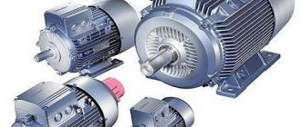
How to find out the speed of an electric motor
How to determine the rotation speed of an electric motor?
It is obvious that the correct operation of any electric machine requires compliance of such an important technical parameter as the rotation speed with the operating conditions.
All the main parameters of an asynchronous electric motor are indicated by the manufacturer on a metal tag - a nameplate attached to its body. And of course, the given technical data necessarily contains information about the rotation speed at rated load.
However, in practice, there are quite often cases when it is necessary to determine the speed of an engine with a missing nameplate or with unreadable - erased inscriptions on it.
Of course, in such cases, an experienced electric drive technician will certainly be able to determine the rotation speed, but novice electricians involved in servicing electrical equipment may have some difficulties in resolving this issue.
The easiest way to determine the rotation speed of the shaft of a working “asynchronous machine” is with a tachometer. But, given that due to the narrow specificity of use, the presence of this measuring device is very rare, this method is not considered here.
We hope the method suggested below will be useful. It is applicable for small and medium power asynchronous electric motors with single-layer stator windings.
So, in our case, determining the rotation speed of an electric motor involves inspecting its stator winding. Therefore, you will need to remove the cover (bearing shield) from the engine. If a pulley or coupling half is attached to its shaft to transmit motion, we recommend removing the rear shield.
Having removed the cover and the fan impeller from the shaft, unscrew the screws, remove the rear bearing shield, and then inspect the end part of the stator winding. Next, you need to count the number of slots occupied by sections of one coil.
The total number of core slots divided by the number of slots occupied by sections of one coil (quotient) will be the number of poles. Knowing its value, we determine the rotation speed of the asynchronous electric motor:
2 – 3000 rpm; 4 – 1500 rpm; 6 – 1000 rpm.
Here it is worth considering one feature of asynchronous motors - the discrepancy between the speed of rotation of the magnetic field and the rotation of the rotor, so the speed can be 940 rpm instead of 1000 or 2940 rpm instead of 3000.
As you can see, this method of determining the rotation speed from the winding is not particularly complicated, however, it can be simplified; You will need to visually determine which part of the circumference of the stator core is occupied by sections of one coil:
The ½ part of the engine stator core occupied by sections of one coil indicates its rotation speed is 3000 rpm, ⅓ - 1500 rpm, ¼ - 1000 rpm.
How to determine the power and speed of an electric motor without disassembling it.
How to find out the characteristics of an electric motor without markings.
Electric motors as part of gearmotors.
Electric motors have long been included in various gearmotors. They find their application in three-stage MTs3U type. and in two-stage type MTs2U. Electric motors have almost 90% efficiency and do not require constant maintenance. An important parameter is the exceptional environmental friendliness of the electric motor; there are no harmful emissions at all, which makes it indispensable for indoor installation. In short, electric motors are currently recognized as 3 or even 4 times more efficient than traditional internal combustion engines.
But sometimes, in the event of an electric motor failure, the buyer finds out that absolutely no accompanying documentation is attached to it. Marking nameplates, even if they have been preserved, may be in a worn-out, shabby state, so that it is simply impossible to see anything on them. How, then, can you determine the engine power and its speed? Here are some step-by-step tips to help you do this.
It should be borne in mind that the number of revolutions refers to the so-called asynchronous speed. Synchronous speed is the speed of rotation of the magnetic field. Asynchronous speed is slightly lower than synchronous due to the presence of mass in the rotating element, as well as the influence of friction forces, which can significantly reduce the efficiency of the motor. However, in practice these differences are almost never of decisive importance.
There are currently 3 main categories of asynchronous electric motors on the market. The first category of the catalog is motors operating at 1000 rpm. In practice, this number is about 950-970 revolutions, but for clarity, it is still rounded to the nearest thousand. The second category is motors producing 1500 rpm. This is also rounded as the actual range is 1430-1470. The third is 3000 rpm. Although in reality such a motor produces 2900-2970 rotations.
Methods for determining the characteristics of an electric motor.
To determine which of these groups the engine belongs to, you do not need to disassemble it, as some experts advise, in order to secure a work order. The fact is that disassembly of an electric motor can only be carried out by a sufficiently qualified master. In fact, it is enough to open the protective cover (another name is the bearing shield) and find the winding coil. There may be several such coils, but one is enough. If a coupling half or pulley is attached to the shaft, you will also need to remove the lower shield.