Analog multimeter
This type of multimeter displays measurement readings using a arrow, underneath which is a display with different scales of values.
Each scale shows the readings of one or another measurement, which are signed directly on the scoreboard. But for beginners, such a multimeter will not be the best choice, since it is quite difficult to understand all the symbols that are on the display. This may lead to misunderstanding of the measurement results.
Digital multimeter
Unlike analogue ones, this multimeter allows you to easily determine the quantities of interest, while its measurement accuracy is much higher than that of pointer instruments.
In addition, the presence of a switch between different characteristics of electricity eliminates the possibility of confusing one value or another, since the user does not need to understand the gradation of the indication scale.
The measurement results are displayed on the display (in older models - LED, and in modern ones - liquid crystal). For this reason, the digital multimeter is user-friendly for professionals and simple and intuitive for beginners.
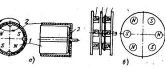
Coil device
Closer to the idealized element - inductance - is a real element of an electronic circuit - an inductive coil. Unlike inductance, the inductive coil also stores the energy of the electronic field and converts electronic energy into other types of energy, namely thermal. Quantitatively, the ability of the real and idealized parts of an electronic circuit to store magnetic field energy is characterized by a parameter called inductance.
Thus, the term “inductance” is used as the name of an idealized element of an electronic circuit, as the name of a parameter that quantitatively characterizes the characteristics of this element, and as the name of the main parameter of an inductive coil.
The relationship between voltage and current in an inductive coil is determined by the law of electrical induction, from which it follows that when the magnetic flux passing through the inductive coil changes, an electromotive force e is induced in it, proportional to the speed of the coil flux linkage configuration ψ and directed in such a way that the current caused by it tends to prevent magnetic flux from changing:
e = - dψ / dt
In SI units, magnetic flux and flux linkage are expressed in Webers (Wb).
Interesting read: instructions on how to ring a transistor.
The magnetic flux F, penetrating any of the turns of the coil, in the general case can contain two components: the magnetic flux of self-induction Fsi and the magnetic flux of external fields Fvp: F - Fsi + Fvp.
The first component is the magnetic flux caused by the current flowing through the coil, the second is determined by magnetic fields, the existence of which is not related to the coil current - the Earth’s magnetic field, the magnetic fields of other coils and permanent magnets. If the 2nd component of the magnetic flux is caused by the magnetic field of another coil, then it is called mutual induction magnetic flux.
The flux linkage of the coil ψ, as well as the magnetic flux Ф, can be represented as the sum of two components: the flux linkage of self-induction ψsi, and the flux linkage of external fields ψvp
ψ= ψsi + ψvp
The EMF e induced in the inductive coil, in turn, can be represented as the sum of the self-induction EMF, which is caused by the configuration of the magnetic flux of self-induction, and the EMF caused by the configuration of the magnetic flux of the fields external to the coil:
e = esi + evp,
here esi is the EMF of self-induction, evp is the EMF of external fields.
If the magnetic fluxes of the fields external to the inductive coil are equal to zero and only the self-induction flux penetrates the coil, then only the self-induction emf is induced in the coil.
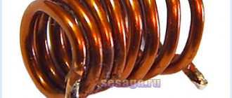
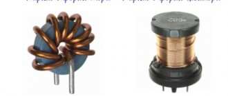
Inductor
it is an insulated wire wrapped repeatedly around a core.
Typically the frame is cylindrical or toroidal.
Inductance is considered the main characteristic of a coil. This quality expresses the ability of an element to convert alternating current into a magnetic field.
Important! Even a single wire is magnetic if the current flowing through it changes. The influence of the camp is directed in such a way as to counteract its change. If it increases, the field slows it down, and if it weakens, it strengthens it.
Inductors
Determining the direction of field lines obeys the “rule of thumb”: if the thumb of a hand clenched into a fist points in the direction of the change in the current force, the closed fingers indicate the direction of the field of force lines.
Consequently, if the wire is wound repeatedly on a cylindrical base, the lines of force of different turns add up and pass through the axis.
To increase the inductance, a ferromagnetic core is placed in the center of the cylinder.
Solenoid inductance
Solenoid-shaped coil (finite length).
A solenoid is a coil whose length is much greater than its diameter (also in further calculations it is assumed that the thickness of the winding is much less than the diameter of the coil). Under these conditions and without the use of a magnetic core, the magnetic flux density (or magnetic induction) B{\displaystyle B}, which is expressed in SI units of tesla, inside the coil away from its ends is (approximately) equal to
B=μNil{\displaystyle \displaystyle B=\mu _{0}Ni/l}
or
B=μni,{\displaystyle \displaystyle B=\mu _{0}ni,}
where μ{\displaystyle \mu _{0}} is the magnetic constant, N{\displaystyle N} is the number of turns, i{\displaystyle i} is the current in amperes, l{\displaystyle l} is the length of the coil in meters and n {\displaystyle n} - winding density of turns in . Neglecting edge effects at the ends of the solenoid, the flux linkage through the coil is equal to the flux density B{\displaystyle B} multiplied by the cross-sectional area S{\displaystyle S} and the number of turns N{\displaystyle N}:
Ψ=μN2iSl=μn2iV,{\displaystyle \displaystyle \Psi =\mu _{0}N^{2}iS/l=\mu _{0}n^{2}iV,}
where V=Sl{\displaystyle V=Sl} is the volume of the coil. From this follows the formula for the inductance of the solenoid (without a core):
L=μN2Sl=μn2V.{\displaystyle \displaystyle L=\mu _{0}N^{2}S/l=\mu _{0}n^{2}V.}
If the coil inside is completely filled with a magnetic core, then the inductance differs by a factor μ{\displaystyle \mu } - the relative magnetic permeability of the core:
L=μμN2Sl=μμn2V.{\displaystyle \displaystyle L=\mu _{0}\mu N^{2}S/l=\mu _{0}\mu n^{2}V.}
In the case when μ>>1{\displaystyle \mu >>1}, under S
You can understand the cross-sectional area of the core and use this formula even with thick winding, unless the total cross-sectional area of the coil exceeds the cross-sectional area of the core many times.
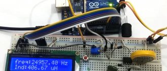
Inductance meter for multimeter
Despite the fact that it is rarely necessary to determine inductance when working with electronics, sometimes it is still necessary and multimeters that measure inductance are difficult to find. In this situation, a special attachment for a multimeter will help, allowing you to measure inductance.
Often, for such a set-top box, a digital multimeter is used, which is configured to measure voltage with a measurement accuracy threshold of 200 mV, which can be purchased at any ready-made electrical and radio equipment store. This will allow you to create a simple digital multimeter attachment.
Measuring devices for a specific assessment of the value of the measured capacitance include microfaradmeters, the operation of which is based on the dependence of the current or voltage in the alternating current circuit on the value of the measured capacitance included in it. The capacitance value is determined by the comparator scale.
In a broader sense, symmetrical AC bridges are used to measure the characteristics of capacitors and inductors, allowing a small measurement error (up to 1%) to be obtained. The bridge is powered by generators operating at a fixed frequency of 400-1000 Hz; electric rectifiers or millivoltmeters, as well as oscilloscope indicators, are used as indicators.
This measure is achieved by balancing the bridge as a result of alternate adjustment of its two arms. Readings are taken from the limbs of the arms of those shoulders that serve to balance the bridge.
As an example, consider the measuring bridges that are the basis of the EZ-3 inductance (Fig. 1) and the E8-3 capacitance meter (Fig. 2).
With a weighbridge (Fig. 1), the inductance of the coil and its quality factor are determined by the formulas Lx = R1R2C2; Qx = wR1C1.
When balancing jumpers (Fig. 2), the measured capacitance and loss resistance are determined by the formulas
Measuring capacitance and inductance using the ammeter-voltmeter method
To measure small capacitances (less than 0.01 - 0.05 μF) and high-frequency inductors in the spectrum of their operating frequencies, resonant methods are widely used. The resonant circuit usually contains a high-frequency oscillator, inductively or via capacitance, connected to the LC measuring circuit. High-frequency sensitive devices that respond to current or voltage are used as resonance indicators.
The ammeter-voltmeter method is used to determine relatively large capacitances and inductances when the measuring circuit is powered from a low-frequency source of 50 - 1000 Hz. For measurements, you can use the diagrams in Fig.
According to instrument readings, impedance
where is it
from these expressions one can find
When active losses in a capacitor or inductor can be neglected, use the circuit in Fig. 4. In this case
Measuring the mutual inductance of 2 coils can be carried out using the ammeter-voltmeter method (Fig. 5) and the method of alternately connected coils.
When measuring using the second method, the inductance of 2 alternately connected coils is measured when the coils are turned on with a consonant LI and a counter LII. Mutual inductance is calculated using the formula
Inductance measurements can be performed using one of the methods described above.
Microcontroller
ATMega328p, operating at a frequency of 16 MHz, was selected as the control microcontroller.
The microcontroller is connected to a Chinese clone of Arduino Nano v3 ($1.5). The microcontroller generates a PWM signal through an eight-bit counter with a divider of 8, so the frequency of the PWM signal is 16 * 10^6 /255 /8 = 7.8 kHz, which fits within the maximum 20 kHz available to the driver.
The microcontroller ADC divider is set to 128; Since each measurement requires approximately 13 clock cycles, the maximum frequency of current flow measurements is approximately 16 * 10^6 / 128 / 13 = 9.6 kHz. Measurements are made in the background, notifying the main program of completion by calling the appropriate interrupt.
Set-top box assembly
You can assemble a tester connecting to a multimeter to measure inductance without problems at home if you have basic knowledge and skills in the field of radio engineering and soldering of microcircuits.
In the circuit, you can use transistors KT361B, KT361G and KT3701 with any letter designations, but for more accurate measurements it is better to use transistors marked KT362B and KT363.
These transistors are installed on the board in positions VT1 and VT2. In position VT3 it is necessary to install a silicon transistor with a pnp structure, for example, KT209V with any letter marking. Positions VT4 and VT5 are for buffer amplifiers.
Most high-frequency transistors are suitable, with h21E parameters for one not lower than 150, and for the other higher than 50.
Any high frequency silicon diode will be suitable for positions VD and VD2.
The resistor can be chosen MLT 0.125 or similar. Capacitor C1 is taken with a nominal capacity of 25330 pF, since it is responsible for the measurement accuracy, and its value should be selected with a deviation of no more than 1%.
Such a capacitor can be made by combining thermally stable capacitors of different capacitances (for example, from 2 to 10,000 pF, from 1 to 5100 pF and from 1 to 220 pF). For other locations, any small-sized electrolytic and ceramic capacitors with an acceptable spread of 1.5-2 times are suitable.
The contact wires to the board (position X1) can be soldered or connected using spring clamps for "speaker" wires. Connector X3 is intended for connecting the set-top box to a multimeter (frequency meter).
It is best to use shorter wire for bananas and alligators to reduce the effect of inductance on the measurement readings. In the place where the wires are soldered to the board, the connection must be additionally secured with a drop of hot glue.
If you need to adjust the measuring range, you can add a switch connector (eg three ranges) to the card.
Rice. 2.41. On the issue of finding the tangent of angle α
When moving to a frequency not equal to 50 Hz, instead of the coefficient, enter into formulas (32) ~ (35) 0,00318
factor
1/2π f
of the circuit power supply, where
f
is the frequency of the circuit power supply.
Almost everyone who is interested in electronics, whether a beginner or an experienced radio amateur, is simply obliged to have measuring instruments in their arsenal. The most common measurements are, of course, voltage, current and resistance. A little less often, depending on the specifics of the work, - transistor parameters, frequency, temperature, capacitance, inductance.
Nowadays there are many inexpensive universal digital measuring instruments, so-called multimeters, on sale. With their help, you can measure almost all of the above quantities. With the possible exception of inductance, which is very rarely found in combined devices. Basically, an inductance meter is a separate device; it can also be found together with a capacitance meter (LC - meter).
Typically, it is not necessary to measure inductance often. For myself, I would even say - very rarely. For example, I unsoldered a coil from some board, but it was unmarked. It’s interesting to find out what its inductance is, so that it can be used somewhere later.
Or you wound the coil yourself, but there is nothing to check. For such occasional measurements, I considered it irrational to purchase a separate device. And so I started looking for some very simple inductance meter circuit
I did not make any special demands on accuracy - for amateur homemade products this is not so important
As a means of measurement and indication in the circuit described in the article, a digital voltmeter with a sensitivity of 200 mV
, which is sold as a ready-made module.
I decided to use a regular UNI-T M838
with a measurement limit of
200 mV
DC voltage. Accordingly, the circuit is simplified, and ultimately takes the form of an attachment to a multimeter.
Fragment excluded. Our magazine exists on donations from readers. The full version of this article is available only
I will not repeat the description of how the circuit works; you can read everything in the original article (archive below). I'll just say a little about calibration.
Multimeter attachment housing
The body can be made from a ready-made box of a suitable size, or you can make the box yourself. You can choose any material, such as plastic or thin fiberglass. The box is adapted to the size of the table and has holes for mounting. There are also holes for connecting wiring. Everything is fixed with screws.
The set-top box is powered from the mains via a 12 V power supply.
What is called inductive reactance
When an alternating voltage is applied to a coil, the current flowing through it changes according to the applied voltage. This causes a change in the magnetic field, which creates an electromotive force that prevents this from happening.
Measuring circuit
In such a circuit, there is a dependence of the electrical parameters of two types - conditional and inductive. They are designated R and XL respectively.
Under normal conditions, the power supply is assigned. However, on reactive elements it is zero. This is due to the constant reversal of the direction of alternating current.
During the oscillation period, energy is pumped into the coil twice and returned to the source the same number of times.
Definition of inductance
Inductance, its unit is si. Inductance of a long solenoid.
Inductance
(or
coefficient of self-induction
) - a coefficient of proportionality between the electric current flowing in any closed circuit and the magnetic flux created by this current through the surface, the edge of which is this circuit. .
— magnetic flux, — current in the circuit, — inductance.
They often talk about the inductance of a straight long wire (see). In this case and other cases (especially in those that do not correspond to the quasi-stationary approximation) when a closed loop is not easy to adequately and unambiguously indicate, the above definition requires special clarification; The approach (mentioned below) that relates inductance to magnetic field energy is partly useful for this.
Inductance is used to express the self-inductive emf in a circuit that occurs when the current in it changes:
.
From this formula it follows that the inductance is numerically equal to the self-inductive emf that occurs in the circuit when the current changes by 1 A in 1 s.
For a given current strength, inductance determines the energy of the magnetic field created by this current:
.
Setting up an inductance meter
To calibrate the inductor tip, several inductive coils with known inductances (for example, 100 µH and 15 µH) are required.
The coils are connected in turn to the attachment, and, depending on the inductance, the trimmer resistor slider on the multimeter screen sets the value to 100.0 for a 100 µH coil and 15 for a 15 µH coil with an accuracy of 5%.
In the same way, the device is adjusted to other ranges. An important factor is that accurate test inductance values are required to accurately calibrate the tip.
An alternative method for determining inductance is the LIMP program. But this method requires some preparation and understanding of the program.
But in both the first and second cases, the accuracy of such inductance measurements will not be very high. This inductance meter is not very suitable for working with high-precision equipment, but for home use or radio amateurs it will be an excellent assistant.
Measurement examples
DC 200 mV 15 Volt
Results of 100 µH inductance measurements
First range
Second range
Third range
Using the LIMP program
Disadvantages of the scheme:
You need an additional multimeter and an external power supply, somewhat complex and incomprehensible calibration (especially when there is nothing to calibrate), low measurement accuracy, and the upper limit is too small.
I believe that this simple inductance meter can be useful for beginning radio amateurs, as well as for those who do not have enough money to purchase an expensive device.
The use of this meter is justified in cases where there are no strict requirements for the accuracy of measurements of absolute inductance values.
The meter can, for example, be useful for monitoring the inductance of windings when winding chokes of network filters that suppress common-mode interference. In this case, the identity of the two windings of the inductor is important in order to prevent saturation of the core.
Sources
1. Article. To help the radio amateur. Issue 10. Information review for radio amateurs / Comp. M.V. Adamenko. - M.: NT Press, 2006. - P. 8.
How to check a fluorescent lamp starter
The process of checking fluorescent lighting devices involves not only checking the integrity of the spiral inside the light bulb, but also the operation of the acceleration and starting systems.
- capacitors that should not swell, deform or explode when exposed to excessive voltage in the electrical network;
- a light source bulb that cannot be dimmed.
The integrity of the capacitor is checked with a multimeter in ohmmeter mode with the maximum possible resistance measurement range.
If the tester reading is less than 2.0 MΩ, it can be assumed that the capacitor has unacceptable leakage current. As practice shows, the best option when carrying out independent repair work would be to completely replace all worn-out elements (starter and throttle valve) with new devices of a similar type.
Current sensor and its testing
The Allegro ACS714 ($3) Hall sensor was selected as a current sensor, producing an analog signal centered at 2.5V and 185mV/A, typical error 1.5%.
An RC circuit was added to the sensor as a low pass filter with a cutoff frequency of 16kHz. The current sensor was powered from a 4.96V source; a resistor was connected in series with the sensor, through which 2A was passed. The theoretical voltage at the output pin should be 4.96/2 + (2 * 0.185 +- 1.5%), the measurement showed 2.84 V, which fits within the calculated parameters. Then the direction of current flow through the resistor was changed, at -2A the measured voltage at the output pin of the sensor was 2.11V, which again fits into the calculated parameters:
This check was necessary because... I bought several breadboards with ACS712 and ACS714 from different manufacturers, and only one was included in the datasheet parameters!
Typical examples of using an LCR meter and a transistor tester for checking radio components
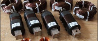
Resistors are the most common type of radio components
Wirewound resistors with different power ratings
| If there are no problems with common values, measuring low resistance resistors can complicate the task. With a conventional multimeter you can often measure normal resistance of the order of 1-2 ohms and higher; if lower, then the resistance of the wires, probes and low resolution begin to have a strong effect. Even the fairly accurate UNI-T UT61E has a measurement resolution in this mode of only 10 mOhm, while even an inexpensive LCR meter has a minimum resolution of 0.1 mOhm. | Digital multimeter UNI-T UT61E high accuracy with the ability to connect to a PC for deleting logs |
Accordingly, if using a multimeter it is possible to relatively accurately measure resistors with a resistance of 0.05-0.1 Ohm, then when measuring 10 mOhm, practically nothing can be measured; for comparison, below is the measurement of two resistors with a nominal value of 1 and 2.2 mOhm.
Difference between multimeter and RLC tester readings when measuring low resistance resistors
Low resistance measurements are often required when testing, sizing or manufacturing current sensing shunts. An alternative option for measuring voltage drop, but requires an adjustable power supply, ammeter, voltmeter.
The current shunt is a low resistance resistor which is a low resistance resistor
The ability to measure low resistance is also useful for detecting problems such as marking errors, especially low resistance resistors.
The resistor on the left is labeled as 0.1 ohm, on the right as 0.22 ohm, but in reality they have almost the same resistance. Such mistakes can sometimes be very costly.
Before installing or soldering a resistor in a circuit, check its resistance. Make sure the nominal and actual values of the resistor are the same
Transistors
Measuring low resistances will help evaluate the originality of field-effect transistors. Currently, more and more counterfeit transistors and transistors with altered markings are appearing on the market. While simply measuring resistance doesn't give you the full picture, it does give you a quick idea of what's in front of you.
For the test, in addition to the device, a 9-volt battery is sufficient. Datasheets often refer to a gate voltage of 10 volts, but this is not relevant in this case. In addition, it is correct to measure the drain-source resistance by current; it is usually indicated in the documentation, but for this you need at least a laboratory power supply.
To test the transistor: we connect test probes to the drain and source terminals (usually the center and right), and apply 9 volts to the outer terminals. A constant voltage application is not required, just charging the gate capacitor is enough, but you need to be careful not to accidentally connect the battery to the tester probes. You can also “load” the transistor first, and only then connect the probes.
Capacitors
Capacitors are used somewhat less frequently, but have their own characteristics. For example, unlike resistors, they are much more susceptible to aging, especially when it comes to electrolytic capacitors installed in switching power supplies, motherboard converters, etc.
The ESR of capacitors is of particular importance. When a capacitor dries with almost no loss of capacity, its internal resistance increases significantly.
This cannot be diagnosed with a regular multimeter; you can change everything, but this is not always convenient, often difficult or expensive. Additionally, RLC meters often allow measurements to be made without desoldering the component, although this of course depends on the wiring diagram.
- Most multimeters measure the capacitor as ideal, that is, without taking into account its features, sometimes this is enough, sometimes not.
- More sophisticated devices can separate the capacitor from its internal resistance and measure these parameters separately.
- The equivalent circuit of a capacitor looks much more complex - all these parameters can be measured, but this is a completely different class of devices that ordinary radio amateurs usually do not need.
Equivalent series circuit, where R is the electrical resistance of the capacitor insulation, responsible for the leakage current, and the equivalent series resistance; L—equivalent series inductance; - capacitor capacity
For example, a comparison of two capacitors, cheap and branded Chinese. Although accurate, a conventional multimeter considers them almost identical, showing only a slight difference in capacitance. But if you connect the capacitors to an LCR meter, you can see that the difference in their internal resistance is almost 5 times! If you plan to use capacitors when switching power supplies, it is this resistance difference that will affect heating and, as a result, the service life and characteristics of the power supply. Capacitors with high internal resistance cannot effectively suppress peaks.
Chokes and inductors
Reactors, transformers, and winding units in general, unlike capacitors and resistors, are even more difficult to control, and typically a multimeter can measure inductance.
The main characteristic of the narrowing is inductance, that is, a coefficient that determines the dependence of the rate of change of electric current on the voltage on the coil
An impedance meter facilitates the manufacture of winding units, as well as the search for short circuits between turns. Compared to a good component or a component of known rating, you can tell that the transformer or inductance is faulty because its inductance will change greatly.
Electrical monitoring of inductors includes detection of turn short circuits (short circuits between winding turns). If there is an interturn circuit in the studio winding, its inductance will drop sharply.
Typically, there are indicators to detect shorted loops, but an impedance meter will also detect this problem. For example, on the left there is a working transformer, on the right it is the same, but with a shorted turn. It can be seen that the winding inductance has become significantly smaller, and the turn also affected the result of measuring the active resistance of the winding.
Comparison of the inductance of a working transformer and a closed-loop transformer
Logs
I struggled for a long time with how to record what was happening inside the microcontroller, because it has very little memory.
As a result, I discovered that the native SPI interface is very fast, and as a result, all debugging information is transmitted by the microcontroller via the SPI interface; a widely available ($10 on Dilextreme, $6 on AliExpress) Chinese clone of the Saelae Pro 8 Logic logic analyzer was used to record it. After very simple manipulations of flashing VID/PID, it can be used with native software from Saelae. I use sigrok (pulseview). It has an extremely simple log file format, which I simply read with my homemade fifty-line program. I bought this analyzer on the advice of gbg, who repaired my Spectrum remotely for me (thank you very much!), and I consider it the best investment in the last two years. For example, I applied a sinusoidal signal (in PWM) to the output of the controller, and the logic analyzer sees it perfectly:
All this was put together, the photo is given in the title of the post.
Almost all the articles that I post here are my work diary. I learn something (in this case management theory) and diligently write down what I learn. The best way to write it down is to write an explanation of how it all works. Then I post the articles on different platforms, for example here.
I have two goals when writing text:
a) get feedback from people who know more than me.
For example, almost everything that I learned for these two articles was told to me by dear Arastas, please love and favor: a person who spends his personal time teaching idiots like me.
Again, gbg, who wrote me linear algebra for my computer graphics lectures, and then debugged the electronics for me over the phone many thousands of kilometers away.
b) just write:
This way I get a library of personal experience, which I return to periodically.
By the way, thematic media, what percentage of authors agree to your support program terms?
Fourier transform
The first thing you need to understand when reading my texts is that I believe that a function and a vector are the same thing.
All the talk about infinity bores me and obscures the essence of what is happening. Generalized functions and the like are a way of looking at pathological cases using the same language as cases where there is no pathology. It’s just that I’m not interested in pathologies. Valery Ivanovich Opoytsev (Boss) spoke well on this topic:
In any field, it is useful to be in a suitable environment of oral communication, where the bookish husks fall off.
Sometimes nothing changes in essence, but there is a feeling of falling into a rut and liberation from dogma. For science, which is always wearing a mask, this is especially important. The essence is behind the scenes, before the eyes - lace. And there is always something missing. Either simplicity, or complexity, but you can’t determine exactly what. Something is moving somewhere, you are on the sidelines, and time is disappearing into the sand, not to mention life. Next, an attempt is made to move the situation forward by simulating a writing environment where the “veils fall away.” The external outline of the content is more or less unclear from the table of contents, but the main goal is what is behind the scenes. Remove the veil, makeup, remove the decorations. Oversimplify, even lie a little, because dosing the truth is the cornerstone of explanation. The results, overloaded with details, do not fit where they should. The epiphany happens when the plump head falls to the level of “two times two”, while the count goes on in the millions. Such is the dialectic here.
If we have a vector (7,12,18,-2), then it can be considered as a set of coefficients in a weighted sum.
7*(1,0,0,0) + 12*(0,1,0,0) + 18*(0,0,1,0) + (-2)*(0,0,0,1) . In exactly the same way, we can consider this vector to be the values of the function at points 0, 1, 2, 3, because our vectors (0,1,0,0) and similar ones can be considered as a shift of a unit impulse: If we constantly increase the number of vectors (shifted unit impulses ) in the basis, we get the usual functions. Unfortunately, such a basis can be quite inconvenient to work with. Let's take the following function as an example:
We have already talked about what the Fourier transform is. In short, this is a change of basis.
In our case, the Fourier transform is a function from real numbers to complex numbers:
A function's argument (real number) is simply the number of the basis function or vector (actually, a pair of basis functions), and its value is the corresponding (pair of) coordinates in for those two vectors in the basis. The Fourier basis is the sines and cosines of various frequencies. The frequency is the number of the basis function.
For our specific function f(t), which is already a weighted sum of sine and cosine, it is very easy to calculate its expansion into a Fourier basis:
That is, our function f(t) has zero coordinates for all basis vectors, except for vectors number 11 and 41.
How is the Fourier basis useful? For example, because the differentiation operation linearly transforms this basis. Let's say we want to calculate the Fourier transform of the derivative f'(t). How to do it? As an option, straight forward: first calculate the derivative, and then calculate the Fourier transform:
Obviously, when differentiating sin(x), it will become sin(x+90°), that is, it is extremely easy to find a correspondence between the Fourier basis expansion of the original function and its derivative: Multiplication by
i
is simply a rotation of the complex plane, which corresponds to +90° in the argument of our function. That is, the differentiation operation, which is difficult to do in the basis of unit impulses, in the Fourier basis is simply scaling and rotating by 90 degrees. Beautiful, is not it?
Laplace transform
Approximately the same story happens with the Laplace transform.
Unfortunately, unlike the Fourier basis, the Laplace basis is non-orthogonal, and therefore is a little more complex for intuitive understanding. Well, that's not the point. Laplace went a little further. If Fourier had only sinusoids in his basis, then Laplace had sinusoids with exponential decay in his basis. Where did he get them from? This is extremely, extremely useful for solving linear differential equations. Let's think about what function transforms into itself upon differentiation? Exhibitor. What about differentiation twice? Sinus. And their combinations give all possible functions that can appear when solving (linear) diffuses, which is what the Marquis de Laplace used. We will not go into details of how these properties are derived (it’s better to carefully consider the properties of the Fourier basis, it is simpler), let’s just note the following facts:
1. Laplace transform is linear:
2. The Laplace transform of the derivative is an affine action on the transformation of the function itself: 3. So, if we have a DC motor, then the flowing current I(t) and the terminal voltage U(t) are related by the following differential equation, where w(t ) is the speed of rotation of the motor shaft: Here L is the inductance and R is the resistance, which is what we are looking for. I will not repeat where this diffuser comes from, since I have already described it in detail and on my fingers (see “Maxwell’s equations on my fingers”).
Since our task is to find L and R, let's rigidly fix the motor shaft, thus forcing w(t) to be zero:
On the advice of Arastas, I supplied two types of signals to my engine: a square wave and a sine wave. Then I measured the current flowing, the picture looks something like this:
Here the blue traces are the input voltage that I am monitoring, and the green ones are the current measurements taken with the ACS714.
My microcontroller code, which generates 11 experiments with square waves and sinusoids of various amplitudes and frequencies, can be viewed here.
Let's solve our differential equation for both types of voltage signal, obtain a parametric current output, and adjust the parameters so that the theoretical curve approximates the actual measurements as best as possible.
Carrying out inductance measurements
After assembly, you need to check the connection of the multimeter. There are several ways to control the device:
- Determination of the inductance of the measuring connection. To do this, you need to short-circuit two wires intended for connection to the inductive coil. For example, if the length of each wire and jumper is 3 cm, one turn of the induction coil is formed. This coil has an inductance of 0.1 - 0.2 μH. When determining inductance more than 5 μH, this error is not taken into account in the calculations. In the range of 0.5 - 5 µH, when measuring, it is necessary to take into account the inductance of the device. Readings below 0.5 µH are approximate.
- Measuring an unknown inductance value. Knowing the frequency of the coil, using a simplified formula for calculating inductance, you can determine this value.
- If the response threshold of silicon pn junctions is higher than the amplitude of the measured electrical circuit (from 70 to 80 mV), you can measure the inductance of the coils directly in the circuit itself (after it has been de-energized). Since the capacitance of the set-top box (25330 pF) is of great importance, the error of such measurements will not be more than 5%, provided that the capacitance of the measured circuit does not exceed 1200 pF.
When connecting the set-top box directly to the coils located on the board, 30 cm long wiring with clamps for fixation or probes is used. The threads are twisted at the rate of one turn per centimeter of length. In this case, the attack inductance is formed in the range of 0.5 - 0.6 μH, which also must be taken into account when measuring inductance.
Measuring inductance and capacitance using a multimeter and computer
Today on the market there are many relatively cheap digital multimeters that measure resistance over a wide range and capacitor capacitance up to 20 μF or more. However, devices that measure inductance are relatively expensive, and they are not needed every day.
The repairman often has to measure the inductance of relay coils, transformer windings, etc. to determine their serviceability. At the same time, independent production of a device or attachment for measuring inductance is complicated by the fact that it requires a power source and a frequency meter to configure the generator. It should be noted that in such devices (attachments) offered in various sources, the stability of the frequency and amplitude of the generator is not high. Hence the measurement accuracy is also not high.
We offer an extremely simple device based on a computer and a digital voltmeter that allows you to measure inductance from 10 μH to 1 H and capacitance from 10 pF to 1 μF with a fairly high accuracy, which is determined by the accuracy of the voltmeter.
As is known, the inductive impedance is described by the formula:
Let's rewrite the formula as follows:
ZL = kL where k = 2πf is the proportionality coefficient.
To simplify the measurement process, we calculate f in such a way that k equals exactly 100000:
f = k/2π = 100000/6.2831853 = 15915.4943 Hz.
As you can see, for k = 10000 a frequency of 1591.5 Hz is required, and for k = 1000 - 159.15 Hz.
The principle of operation of the inductance meter is shown in Fig. 1, and in Fig. 2 - the capacitance meter. In both cases, the computer (more precisely, its sound card) acts as a generator of a highly stable frequency and voltage test signal, and the multimeter acts as an alternating current voltmeter.
If the resistance of the signal source exceeds the load resistance by 10 times or more, we can assume that this signal source is a current source. To fulfill this condition, the complex resistance of the measured inductance should not exceed 1/10 of resistor R1.
The output voltage of the generator should be equal to 1 V (rms value), while the voltage across the measured inductance should not exceed 100 mV.
Millivoltmeter U2 is used at the 100 mV limit. The sound card of the computer (laptop) is used as the signal source. In this case, wav files recorded using an audio editor (for example, GoldWav) with a level of 0 dB are used as test signals. The output voltage of a sound card is usually slightly more than 1 V. The required voltage is set with the volume control. If it is still less than 1 V (which may be the case in some laptops), then you will have to use a correction factor, which introduces some inconvenience during measurements. Let's assume the output voltage of the sound card is 0.91 V. In this case, the correction factor is k = 1/0.91 = 1.1.
A simplified version of the device is shown in Fig. 3, in which a digital multimeter with automatic range switching turned on as a voltmeter is shown as a pointer device.
The measurement limits using this device are summarized in the table.
To quickly switch resistors, you can use a 3-position switch. The measurement limits can be expanded if you additionally use 100 kOhm and 1 MOhm resistors.
When the voltmeter readings are less than 10 mV and more than 100 mV, to increase the accuracy of measurements, you should switch to a different range. This can be done in two ways: changing the frequency and switching the resistor value.
If, when measuring inductance, the voltage across the inductance being tested is more than 100 mV, then it is necessary to increase the resistor or reduce the signal frequency, and vice versa for a voltage less than 10 mV.
If, when measuring capacitance, the instrument readings are more than 100 mV, then it is necessary to reduce the resistor or increase the frequency, and vice versa for voltages less than 10 mV.
| Test signal frequency, Hz | Measuring range of inductances and capacitances with the resistance of resistor R1 | ||
| 100 | 1 to | 10k | |
| 15915 | 10…100 µH | 0.1…1 mH | 1…10 mH |
| 1…10 nf | 100…1000 pf | 10…100 pf | |
| 1591,5 | 0.1…1 mH | 1…10 mH | 10…100 mH |
| 10…100 nF | 1…10 nf | 10…1000pF | |
| 159,15 | 1…10 mH | 10…100 mH | 0.1…1 H |
| 0.1…1 µF | 10…100 nf | 1…10 nf |
Simplified meter design
To make it, you will need a cable with a minijack connector, for example, from failed player phones. If you need an inductance meter in the range of 0.1 ... 100 mH, then you can get by with just one 1 kOhm resistor and three files of the above signals.
Figure 4 shows such a meter with two SMD type resistors with nominal values of 1 kOhm and 10 kOhm, while the measurement limits are expanded by an order of magnitude.
Source
Lc meter circuit on a microcontroller
Setup and features
The heart of the device is the PIC18F2520 microcontroller. For stable operation of the generator, it is best to use non-polar or tantalum capacitors such as C3 and C4. You can use any relay that matches the voltage (3-5 volts), but preferably with the lowest possible contact resistance in the closed position. For sound, a buzzer without a built-in generator or a regular piezoelectric element is used.
When you first start the assembled device, the program automatically starts the display contrast adjustment mode. Use buttons 2/4 to set the contrast to an acceptable level and press OK (3). After completing these steps, the device should be turned off and on again. The menu has a “Settings” section for some settings for the operation of the device. In the “Capacitor” submenu, you must specify the exact value of the calibration capacitor used (C_cal) in pF. The accuracy of this estimate directly affects the accuracy of the measurement. You can check the operation of the generator itself using a frequency meter at test point “B”, but it is better to use the frequency control system already built into the “Generator” submenu.
By selecting L1 and C1, it is necessary to obtain stable frequency readings in the range of 500-800 kHz. High frequency has a positive effect on measurement accuracy; At the same time, as the frequency increases, the stability of the generator may deteriorate. It is convenient to monitor the frequency and stability of the generator, as I said above, in the “Oscillator” menu section. If you have an external calibrated frequency meter, you can calibrate the LC meter frequency meter. To do this, connect an external frequency meter to test point “B” and use the +/- buttons in the “Oscillator” menu to select the constant “K” so that the readings of both frequency counters coincide. For the battery status indication system to work correctly, you need to set up a resistive divider on resistors R9, R10, then install jumper S1 and write the values in the fields of the “Battery” section.
RF detector attachment for multimeter
The simplest circuit of an attachment to a digital multimeter for measuring RF alternating current. Suitable for measuring the power of an audio amplifier or radio transmitter. The multimeter must be integrated with a simple external measuring head containing a high-frequency germanium diode detector. This circuit rectifies and filters the AC signal voltage, converting it into an easily measurable DC voltage.
The input capacitance of the RF head is less than 3 pF, which allows it to be connected directly to a cascade circuit. You can use Soviet high-frequency diodes D9, GD507 or D18. The RF head is assembled in a shielded housing on which terminals are located for connecting the probe or wires to the circuit being measured. Communication with the tester must be carried out using a shielded television cable.
2.32. Measuring the inductances of low-frequency coils
2) use an AT autotransformer to set the voltage at 10 V and note the voltmeter reading U1, that is, the voltage drop across the coil being tested;
3) move the switch slider from position 1-3 to position 1-2, thus connecting a voltmeter in parallel with the resistor, and select a resistance value R = R2 at which the voltage drop across the resistor is also equal to U1.
4) calculate the inductance of the coil using the formula:
L'x = 0.00318 √RR2 Hn, (32)
where R1 and R2 are the resistance of the resistor (Ohm) when the switch slider is in positions 1-3 and 1-2.
In the absence of a variable resistor, the inductance of the coil is measured using a fixed resistor. The measurement scheme and process remain the same, but the formula for calculating Lx is supplemented with the factor U1/U2, that is, it takes the form:
L”x = 0.00318 R(U1/U2) H, (33)
where R is the resistor resistance, Ohm,
U1 and U2 - voltmeter readings in positions 1-3 and 1-2 of the switch slider.
In most cases, the inductive resistance of the windings is much higher than their active resistance, so the above formulas give fairly accurate inductance values.
However, if the number of coil turns is small, and the resistance to direct (or alternating) current is high (several tens or hundreds of Ohms), then L'x and L”x are calculated using other, more accurate formulas, namely:
(34)
where R is the resistor resistance when the switch slider is in position 1-2; U is the voltage across R and Lx connected in series; U2—voltage on the resistor equal to voltage U1 on the Lx coil;
Lx” = 0.00318 R0 / tg α,
where R is the active resistance of the winding;
α is the angle formed by side BC of triangle ABC (Fig. 2.40) and the perpendicular lowered from point B to the continuation of side LS.
How to check the choke of a fluorescent lamp?
The starter is an inductor wound on a ferromagnetic core with high magnetic permeability. It is an integral part of electromagnetic power supplies (EMPRA). In the ignition phase of the LDS, it, together with the starter, ensures heating of the cathodes, and then creates a high voltage pulse (up to 1000 V) to create a luminescent discharge in the cylinder due to its characteristic electromotive force (EMF) self-induction.
Once the starter has been removed from service, inductive reactance is used by the inductive reactance to maintain the discharge current through the LDS at the level required to continuously and stably ionize the gas-mercury mixture used in the cylinder. The amplitude of the inductance is such that the resistance of the AC inductor protects the coil electrodes from overheating and burning out.
The performance of the inductance of a fluorescent lamp can be checked by measuring the resistance using an ohmmeter. It is part of the electrician's combination instrument.
If you check the fluorescent lamp accelerator with a multimeter, you may find it in good condition, in which the measured active resistance matches the data in its data sheet, or you may encounter inconsistencies. After analyzing them, we can draw a conclusion about the nature of the detected defect. Short circuits are accompanied by an unpleasant odor and discoloration of the protective insulation. If there is an external manifestation or detection of a deviation of the measured resistance value from its nominal value, the inductance must be replaced.
Checking the inductance of a fluorescent lamp.
Introduction
If someone came up with the idea of conducting a survey of the world's population on the topic “What do you know about inductance?”, the overwhelming number of respondents would simply shrug their shoulders. But this is the second most numerous technical element, after transistors, on which modern civilization is based! Detective fans, remembering that in their youth they read Sir Arthur Conan Doyle’s exciting stories about the adventures of the famous detective Sherlock Holmes, will, with varying degrees of confidence, mutter something about the method that the above-mentioned detective used. At the same time, implying the method of deduction, which, along with the method of induction, is the main method of knowledge in Western philosophy of the New Age.
With the induction method, individual facts, principles are studied and general theoretical concepts are formed based on the results obtained (from particular to general). The deduction method, on the contrary, involves research from general principles and laws, when the provisions of the theory are distributed into individual phenomena.
It should be noted that induction, in the sense of method, does not have any direct relation to inductance, they simply have a common Latin root inductio
- guidance, motivation - and mean completely different concepts.
Only a small part of those surveyed from among the exact sciences - professional physicists, electrical engineers, radio engineers and students in these fields - will be able to give a clear answer to this question, and some of them are ready to give an entire lecture on this topic right away.
Definition of inductance
In physics, inductance, or the coefficient of self-induction, is defined as the coefficient of proportionality L between the magnetic flux Ф around a current-carrying conductor and the current I generating it, or - in a more strict formulation - this is the coefficient of proportionality between the electric current flowing in any closed circuit and the magnetic flux created by this current:
or
To understand the physical role of the inductor in electrical circuits, one can use the analogy of the formula for the energy stored in it when current I flows with the formula for the mechanical kinetic energy of the body.
For a given current I, inductance L determines the energy of the magnetic field W created by this current I:
Similarly, the mechanical kinetic energy of a body is determined by the mass of the body m and its speed V:
That is, inductance, like mass, does not allow the energy of the magnetic field to instantly increase, just as mass does not allow this to happen with the kinetic energy of the body.
Let's study the behavior of current in inductance:
Rice. 2. Physical implementation of the experiment
Rice. 3. Oscillogram of current through inductance. The yellow oscillogram is the output of the signal generator, the blue one is the signal at the resistor.
Due to the inertia of the inductance, the fronts of the input voltage are delayed. In automation and radio engineering, such a circuit is called an integrating circuit, and is used to perform the mathematical operation of integration.
Let's study the voltage on the inductor:
Rice. 6. Voltage oscillogram across the inductance (blue)
At the moments of applying and removing voltage, due to the self-inductive emf inherent in the inductance coils, voltage surges occur. Such a circuit in automation and radio engineering is called differentiating, and is used in automation to correct processes in a controlled object that are fast in nature.
Rice. 5. By and large, in all electric current generators of any type, as well as in electric motors, their windings are inductor coils.
Calculation methods
There are several basic ways to determine the inductance of a coil. All formulas that will be used in calculations can be easily found in reference books or on the Internet. The entire calculation process is quite simple and will not be difficult for people with basic mathematical and physical knowledge.
Through current
This calculation is considered the simplest way to determine the inductance of a coil. The formula through current follows from the term itself. What is the inductance of the coil can be determined by the formula: L = Ф / I, where:
- L is the inductance of the circuit (in Henry);
- this is the magnitude of magnetic flux measured according to Weber;
- I is the current in the coil (in amperes).
This formula is only suitable for a single-turn circuit. If the coil consists of several turns, the total flux (total value) is used instead of the magnetic flux value. When the same magnetic flux passes through all the coils, then to determine the total value it is enough to multiply the value of one of them by the total number.
Finite Length Solenoid
The solenoid is a long and thin coil whose winding thickness is much less than its diameter. In this case, calculations are made using the same formula as the current strength, only the magnitude of the magnetic flux will be determined as follows: Ф = µ0NS / l, where:
- µ0 is the magnetic permeability of the medium, determined from look-up tables (for air, which is the default value in most calculations, it is 0.00000126 henry/meter);
- N is the number of coil turns;
- S is the cross-sectional area of the chain, measured in square meters;
- l is the length of the solenoid in meters.
The self-inductance coefficient of the solenoid can also be calculated according to the method for determining the magnetic flux energy of the field. This is a simpler option, but it requires some values. Formula for determining inductance: L = 2W / I 2, where:
- W is the magnetic flux energy, measured in joules;
- I is the current strength in amperes.
Toroidal core coil
In most cases, the toroidal coil is wound on a core made of a material with high magnetic permeability. In this case, the infinite length straight solenoid formula can be used to calculate the inductance. It has the following form: L = N µ0 µS / 2 πr, where:
- N is the number of coil turns;
- µ—relative magnetic permeability;
- µ0—magnetic constant;
- S is the cross-sectional area of the core;
- π is a mathematical constant equal to 3.14;
- r is the average radius of the torus.
Sources
- https://NpfGeoProm.ru/teoriya-i-opyt/sposoby-izmereniya-induktivnosti.html
- https://sto82.ru/elektroteoriya/metody-izmereniya-induktivnosti.html
- https://TokMan.ru/praktika/metody-izmereniya-induktivnosti.html
- https://supereyes.ru/articles/multimetry-i-testery/rlc-izmeritel-kak-vybrat/
- https://DiesElit.ru/osnovy/kak-izmerit-induktivnost-katushki-multimetrom.html
- https://drova-pil.ru/novosti/proverka-induktivnosti-multimetrom.html
- https://TeploDom24.ru/teoriya-i-praktika/kak-izmerit-induktivnost-katushki.html
Solenoid inductance
Solenoid-shaped coil (finite length).
A solenoid is a long, thin coil, that is, a coil whose length is much greater than its diameter (also in further calculations here it is implied that the thickness of the winding is much less than the diameter of the coil). Under these conditions and without the use of magnetic material, the magnetic flux density (or magnetic induction) B{\displaystyle B}, which is expressed in SI units of tesla, inside the coil is effectively constant and is (approximately) equal to
B=μNil{\displaystyle \displaystyle B=\mu _{0}Ni/l}
or
B=μni,{\displaystyle \displaystyle B=\mu _{0}ni,}
where μ{\displaystyle \mu _{0}} is the magnetic constant, N{\displaystyle N} is the number of turns, i{\displaystyle i} is the current written in amperes, l{\displaystyle l} is the length of the coil in meters and n{\displaystyle n} is the winding density of turns in . Neglecting edge effects at the ends of the solenoid, the flux linkage through the coil is equal to the flux density B{\displaystyle B} multiplied by the cross-sectional area S{\displaystyle S} and the number of turns N{\displaystyle N}:
Ψ=μN2iSl=μn2iV,{\displaystyle \displaystyle \Psi =\mu _{0}N^{2}iS/l=\mu _{0}n^{2}iV,}
where V=Sl{\displaystyle V=Sl} is the volume of the coil. From this follows the formula for the inductance of the solenoid (without a core):
L=μN2Sl=μn2V.{\displaystyle \displaystyle L=\mu _{0}N^{2}S/l=\mu _{0}n^{2}V.}
If the coil inside is completely filled with magnetic material (core), then the inductance differs by a factor μ{\displaystyle \mu } - the relative magnetic permeability of the core:
L=μμN2Sl=μμn2V.{\displaystyle \displaystyle L=\mu _{0}\mu N^{2}S/l=\mu _{0}\mu n^{2}V.}
In the case when μ>>1{\displaystyle \mu >>1}, one can (should) under S
understand the cross-sectional area of the core and use this formula even with thick winding, unless the total cross-sectional area of the coil exceeds the cross-sectional area of the core many times.