- home
- Rewinding of electric motors
›
Rewinding is a complex and responsible job that must be performed by a professional specialist with sufficient experience and skills in producing this type of service. The production process looks like this: The engine is disassembled, the fan and the motor armature are removed; · The winding parts are removed, the windings are removed, the remaining insulating materials are cleaned off; · Insulation is placed in grooves; · Measure the length of the stator and the width of the insulation groove; · The necessary elements are cut out, the coil template is removed; · Special equipment is used for winding the roll; · Coils are wound with a certain number of turns, which must be distributed evenly; · The coils should not be located on top of each other; · The coils are placed in the stator slots, and insulating material is laid between them; · Frontal strapping is performed; · Phase coils are connected according to the circuit, their terminals are connected in a star, the circuit is aligned; · Ends welded or welded; · The grooves are insulated so that the insulating material does not protrude from them; · Electric motor assembly; · The stator winding is called; · The installation is connected to the network; · Final testing of the devices is being carried out. Rewinding an electric motor is the operation of winding the stator with a round conductor (free winding). It is not recommended to do this alone; for these purposes, we recommend using the rewinding service in Peremotka2.
Features of repairing an asynchronous machine
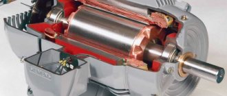
Engine problems of any type can be mechanical or electrical in nature. In the first case, strong vibration and characteristic noise may indicate a malfunction; as a rule, this indicates problems with the bearing (usually in the end cover). If the malfunction is not corrected in time, the shaft may jam, which will inevitably lead to failure of the stator windings. In this case, the thermal protection of the circuit breaker may not have time to operate.
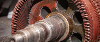
“Burnt” wires of the stator winding
Based on practice, in 90% of failures of asynchronous machines, problems arise with the stator winding (break, interturn short circuit, short circuit to the frame). In this case, the short-circuited armature, as a rule, remains in working condition. Therefore, even if the damage is mechanical, it is necessary to check the electrical part.
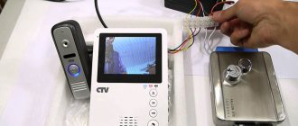
Washing machine tachometer (TCM)
This element is one of the mandatory components included in the design of washing machines. It is placed on the rotational element, responsible for controlling the rotor speed. The product is called a tachogenerator. There are cases when it is also called a Hall sensor. All these elements have the same operating principle.
The specifics of the work are simple:
- The tachometer is located on the motor shaft - a ring with conductors;
- When the engine rotates, voltage is generated inside the TCM - due to the influence of the magnetic field. High RPM equals high voltage;
- the measuring transducer records this, converts the parameters of the working environment into an electrical signal, and transmits it to the control module (MU) of the washing machine. The control system allows you to control the number of revolutions through a human-machine interface, i.e. dashboard.
Untimely maintenance and age of the machine trigger negative processes - degeneration of internal mechanisms and working units. The consequences of this are incorrect speed control, noise increases that are incommensurate with the indicators set by the control module, and the laundry spinning function stops working.
The measuring transducer - tachometer is located at the bottom of the washing machine. His check is notable for disassembling the rear wall of the equipment: unscrewing the mounting bolts. The motor is connected to the pulley via a belt drive. To check it, you need to dismantle the motor located inside the machine.
Algorithm for checking the performance of the tachometer:
- The wires are disconnected, and the resistance on each of the conductors is measured with a multimeter. Normal parameters should be in the range of 60 ohms;
- The measuring device switches to voltage evaluation mode. Measure with one hand and rotate the motor with the other. If the motor is working properly, the indicator should rise, usually 0.2 V;
- testing the bolt clamp - if it is loose, then malfunctions occur.
Non-compliance with at least one parameter is a reason to think about replacing the sensor as soon as possible. Breakdowns occur when the washing machine is overloaded for a long time, for example, with a large amount of laundry exceeding the maximum allowable volume.
Symptoms and replacement
The primary factor is disruption of the washing machine’s usual operation due to the lack of correct data from the control unit. How the problem manifests itself:
- the electric motor uncontrollably gains speed with associated problems occurring - increased vibration, noise, beating on the floor or inside the housing;
- increased load on internal elements provokes accelerated mechanical wear of bearings and shock absorbers - guaranteed failure;
- uncontrolled revolutions of the electric motor lead to a complete imbalance of the mechanisms - this is why a beating is felt inside the washing machine body;
- if there is an inverter part, along with a breakdown of the tachogenerator, a squeak appears, the rotation of the drum is blocked, the sound increases;
- jerk work.
During replacement, the TSM is removed from the washing machine. Initially, the sensor connectors are disconnected. The latter are pulled out, unscrewed, and pulled out with a screwdriver. The cover of the measuring transducer is removed - it is latched. They are made of plastic or metal - the type depends on the class of the washing machine. The bolts securing the tachometer are unscrewed. Assembly is done in reverse.
Winding check
In most cases, the problem can be detected by its appearance and characteristic odor (see Figure 1). If the fault cannot be determined empirically, we proceed to diagnostics, which begins with a continuity test. If one is found, the engine is disassembled (this process will be described separately) and the connections are thoroughly inspected. When no defect is detected, a break can be established in one of the coils, which requires rewinding.
If the continuity test does not show a break, you should proceed to measuring the winding resistance, taking into account the following nuances:
- the insulation resistance of the coils to the housing should tend to infinity;
- for a three-phase drive, the windings must show the same resistance;
- For single-phase machines, the resistance of the starting coils exceeds the readings of the working windings.
In addition, it should be taken into account that the resistance of the stator coils is quite low, so to measure it it makes no sense to use devices with a low accuracy class, such as most multimeters. You can correct the situation by assembling a simple circuit using a potentiometer with the addition of an additional power source, for example a car battery.
Circuit for measuring winding resistance
The measurement procedure is as follows:
- The drive coil is connected to the circuit presented above.
- The potentiometer sets the current to 1 A.
- The coil resistance is calculated using the following formula: , where RK and UPIT were described in Figure 2. R is the resistance of the potentiometer, and is the voltage drop across the measured coil (shown by a voltmeter in the diagram).
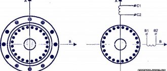
It is also worth talking about a technique that allows you to determine the location of the interturn short circuit. This is done as follows:
The stator, freed from the rotor, is connected through a transformer to a reduced power supply, having previously placed a steel ball on it (for example, from a bearing). If the coils are working, the ball will move cyclically along the inner surface without stopping. If there is an interturn short circuit, it will “stick” to this place.
Steel ball testing
Prices for repairing a three-phase electric motor
| Power, kWt) | Rotation speed, rpm | |||
| 3000 | 1500 | 1000 | 750 | |
| Up to 1.5 | 2740 | 2806 | 3417 | 4057 |
| 2.2 | 3090 | 3245 | 4154 | 4897 |
| 3 | 3642 | 3901 | 4973 | 5179 |
| 4 | 5012 | 4652 | 5413 | 6804 |
| 5.5 | 5296 | 5301 | 5978 | 7511 |
| 7.5 | 6630 | 6919 | 7312 | 11021 |
| 11 | 8139 | 8147 | 9937 | 13182 |
| 15 | 12088 | 12049 | 11737 | 14803 |
| 18,5 | 13001 | 13345 | 15217 | 24450 |
| 22 | 15057 | 15805 | 23408 | 25522 |
| 30 | 17648 | 18202 | 25857 | 29275 |
| 37 | 23803 | 25949 | 30677 | 40080 |
| 45 | 29055 | 28737 | 38389 | 48070 |
| 55 | 34546 | 32811 | 41481 | 60759 |
| 75 | 44670 | 48812 | 64472 | 82899 |
| 90 | 47893 | 51078 | 78166 | 99898 |
| 110 | 67202 | 73052 | 95759 | 122517 |
| 132 | 80848 | 87962 | 114110 | 147423 |
| 160 | 98012 | 106439 | 138740 | 179116 |
| 200 | 123101 | 132548 | 173924 | ———- |
| 250 | 154120 | 167435 | ———- | ——— |
| 320 | 237156 | ————— | ———- | ———— |
| kW | 3000 rpm | 1500 rpm | 1000 rpm | 750 rpm |
COEFFICIENTS USED IN THE CALCULATION:
- Single-phase - 1.5;
- Foreign production -1.5;
- Explosion-proof – 1.3;
- Urgent – 1.5;
- Two-speed – 1.5; Two-speed with independent windings – 2.
- Old model type AO, A, VAO -1.5
Features of repair of commutator drives
This type of electric machine is more likely to experience mechanical failures. For example, brushes worn out or commutator contacts clogged. In such situations, repairs come down to cleaning the contact mechanism or replacing graphite brushes.
Testing the electrical part comes down to checking the resistance of the armature winding. In this case, the probes of the device are applied to two adjacent contacts (lamellas) of the collector, after taking readings, measurements are taken further in a circle.
Checking the armature winding of a commutator motor
The displayed resistance should be approximately the same (taking into account the instrument error). If a serious deviation is observed, then this indicates that there is an interturn short circuit or open circuit, therefore, rewinding is necessary.
Motor winding data
This is a reference data, so the most reliable way to obtain this information is to consult the appropriate sources. This data can also be provided in the product passport.
You can find advice online that recommends manually counting the turns and measuring the diameter of the wire when rewinding. It's a waste of time. It is much easier and more reliable to find all the necessary information using the engine markings, which will indicate the following parameters:
- rated operating characteristics (voltage, power, current consumption, speed, etc.);
- number of wires for one slot;
- Ø wire (as a rule, insulation is not taken into account in this indicator);
- information on the outer and inner diameter of the stator;
- number of grooves;
- with what step the winding is performed;
- rotor dimensions, etc.
Below is a fragment of a table with winding data for electric machines of type 5A.
Example of a table with winding data
Step-by-step instructions for rewinding an electric motor with your own hands
It is necessary to immediately warn that without special equipment and operating skills, rewinding reels will most likely be a useless task. On the other hand, negative experience is also experience. Understanding the complexity of a process is the best explanation of its cost.
The first stage is dismantling
We present an algorithm of actions for asynchronous machines, it is as follows:
- Disconnect the drive from the network (380 or 220 V).
- We remove the electric motor from the structure where it was installed.
- Remove the rear cooling fan shroud.
- We dismantle the impeller.
- We unscrew the fastening of the end covers, and then remove them. It is advisable to start from the front part; after dismantling it, the rotor will easily “come out” from the rear cover.
- We take out the rotor.
This process can be greatly simplified if you use a special device - a puller. With its help, it is easy to free the motor shaft from a pulley or gear, and also remove the end covers.
Puller for dismantling
We will not provide instructions for disassembling a commutator motor, since it is not particularly different. The structure of an electric machine of this type can be found on our website.
Stage two - removing the winding
The sequence of actions is as follows:
- Using a knife, remove the bandage fasteners and insulating coating from the wire connections. Some instructions recommend recording the wiring diagram, for example, by taking a photograph. There is no particular point in doing this, since this is reference information and finding it out by engine brand is not a problem.
- Using a chisel, knock off the tops of the wires from each end of the stator.
- We release the grooves using a punch of the appropriate diameter.
- We clean the stator from dirt, soot, and impregnation varnish.
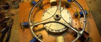
Stator freed from the winding
At this stage, we recommend stopping, picking up the housing and taking it to specialists. Independent dismantling will reduce the cost of restoration work. As mentioned above, without special equipment it is quite difficult to rewind reels efficiently. To understand the complexity of the process, we will describe its technology, which will make the choice easier.
Stator rewinding (final phase)
The process consists of the following steps:
- Installation of insulators in each groove (sleeving).
- The thickness of the material and its characteristics are selected from the reference book.
- Winding data is determined by motor brand.
- A special machine is used to wind the required number of turns of loose coils. You can find photos and parameters of homemade manual machines on the Internet, but the quality of their work is quite questionable.
Bulk Winding Machine - The coil groups are placed in the grooves, after which they are tied and connected. These processes are quite complex and are performed manually.
- Impregnation is carried out. To do this, the body is heated to a temperature of 45°C - 55°C and completely immersed in a container with impregnating varnish. It makes no sense to varnish the wires, since in this case there will still be voids.
- After impregnation, the body is placed in a special chamber, where drying is carried out at a temperature of 130-135°C.
- Final testing of the coils with an ohmmeter.
- Assembly and test run (if only the body, but also other parts and fasteners were transferred for repair).
If only the body was submitted for restoration, we recommend checking the coils before turning on the motor.
Do It Yourself (Knowledge) 2000-04, page 41
in rows and rows it becomes a mechanically strong monolithic mass with good dielectric properties and improved heat removal from its internal layers. In it, the turns are so firmly fastened to each other that the appearance of a short circuit is excluded. turns, and it has a long service life. A reel poorly impregnated with epoxy glue does not have the above properties and its service life is short.
Rewinding reels
To repair pumps, you can contact workshops where specialists will rewind, impregnate the coils and repair them. But this work can be done with success, no worse than in workshops, with your own hands in a home workshop. Our further presentation is based on personal experience in rewinding coils, I’ll check them! and pump assemblies.
To rewind pump coils you need: winding wire, winding paper, epoxy glue for their impregnation and for the terminals a vinyl chloride or linoxin tube with a diameter of 1 mm. The brands of winding wires for the above pumps are given in table. 2. Pump coils in factories are made with PEV-2 wire dH3 = 0.63 mm. It is advisable to rewind the coils with the same wire, but if it is not available, you can use one of the following wires: dH3 = 0.63 mm PET-155 brand, dH3 = 0.61 mm and dH3 = 0.69 PEV-1 brand. When rewinding coils with a wire smaller than dH3 = 0.63 mm, in order to maintain the current density in the wire within 13-14 A/mm2, it is necessary to reduce the current flowing through the coils by reducing the gap between the armature and the magnetic cores according to the graph shown on rice. 4.
We use wrapping paper for laying between the rows; we use tissue, cable or telephone paper with a thickness of 0.1 mm.
We proceed to repair the pump electromagnet in the following sequence:
1. After determining a break in the coils, cut off the power cable near the gland input, unscrew the nut and remove the rubber tube and washer from it.
2. We clamp the pump in a vice and, unscrewing the 4 mounting bolts, disassemble it into two halves, the drive and pressure chambers. When unscrewing the fastening bolts, you must keep in mind that they are secured against self-unscrewing.
3. At the end of the pump and in the magnetic circuit of the drive chamber, we drill two holes 1-12 mm deep and cut M4 threads into them (Fig. 1). These threaded holes are necessary when assembling the pump to install the magnetic circuit in its “native” place.
4. We install the drive chamber housing on an electric stove with a closed spiral with a power of no more than 400 W and cover it with a pan wrapped in asbestos cloth. After 1-1.5 hours, the camera body warms up and the epoxy glue softens. Then, taking it with canvas mittens, we hit it against a massive board, and the electromagnet with coils jumps out of the drive chamber. We place the electromagnet with the coils again on the tile under the pan, and in the meantime, while the chamber body is hot and the glue is softened, we clean the walls of the chamber and the seat under the magnetic circuit from glue, using screwdrivers, files, coarse and fine sandpaper. This cleaning operation must be performed very carefully so that when assembling the pump, the electromagnet fits into place without distortion.
The release of the electromagnet from the drive chamber can be accelerated by heating its body with a blowtorch and also hitting it against the board.
Next, we release the electromagnet from the coils. You have to be very careful here, you can easily break and chip off the cheeks of the plastic frames. We install the electromagnet in a vice so that the bodies of the coil frames sit on their jaws, and, using a piece of wood, carefully hit it with a hammer and knock out the magnetic circuit from the coils (Fig. 5). We also clean the surfaces of the magnetic circuit and coil frames from glue residues.
The last operation is to remove the burnt wire from the coil frames. If the winding was not impregnated or poorly impregnated, then the wire can be easily removed, but if the winding is a monolithic mass, then you have to cut it with a hacksaw. Then we also clean the surfaces of the frame from old impregnation.
39
Rewinding the armature
The process of replacing the winding of a commutator motor is somewhat similar, with the exception of small nuances associated with the design features. For example, the armature is sent for rewinding, not the housing, provided that the problem does not arise with the excitation coils. In addition, there are the following differences:
- For winding, a special machine with a more complex configuration is used.
- Grooving, balancing of the armature (in the final part of the process), as well as its cleaning and grinding are required.
- The manifold is cut using a special milling machine.
The above processes require special equipment; without it, rewinding electric motors is a waste of time.