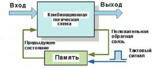
An electrical circuit can be in different states. An example would be on or off. At the moments when the chain moves from one to another, quite complex processes can occur in it, which are called transitional. At this time, in most cases, energy redistribution occurs in a fraction of a second. To understand in more detail how these changes are carried out, knowledge of the two laws of commutation will help.
Switching concept
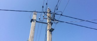
Switching of electrical circuits refers to various switches made in all kinds of electrical connections, as well as in cables, wires, transformers, machines, various devices and devices that, in one way or another, generate, distribute and consume electricity.
As a rule, switching is accompanied by transient processes that arise as a result of the fact that currents and voltages are very quickly redistributed in the branches of electrical circuits.
The principle of operation of Router (router)
A router or router, router (from the English router), is a network device that, based on information about the network topology and certain rules, makes decisions about forwarding network layer packets (layer 3 of the OSI model) between different network segments.
Typically, a router uses the destination address specified in the data packets and determines from the routing table the path along which the data should be sent. If there is no described route in the routing table for an address, the packet is discarded.
There are other ways to determine the forwarding route of packets, such as using the source address, the upper-layer protocols used, and other information contained in the network layer packet headers. Often, routers can translate the addresses of the sender and recipient, filter the transit data stream based on certain rules to limit access, encrypt/decrypt the transmitted data, etc.
The routing table contains information on the basis of which the router decides whether to forward packets further. The table consists of a certain number of entries - routes, each of which contains the address of the recipient's network, the address of the next node to which packets should be transmitted, and a certain weight of the entry - a metric. The metrics of the entries in the table play a role in calculating the shortest routes to various recipients. Depending on the router model and the routing protocols used, the table may contain some additional service information. For example:
192.168.64.0/16 [110/49] via 192.168.1.2, 00:34:34, FastEthernet0/0.1 where 192.168.64.0/16 is the destination network, 110/- administrative distance /49 is the route metric, 192.168.1.2 is the address the next router to which packets for the network 192.168.64.0/16 should be sent, 00:34:34 - the time during which this route was known, FastEthernet0/0.1 - the router interface through which the “neighbor” 192.168.1.2 can be reached.
The routing table can be compiled in two ways:
- static routing
- when table entries are entered and changed manually. This method requires administrator intervention every time changes occur in the network topology. On the other hand, it is the most stable and requires a minimum of router hardware resources to maintain the table. - dynamic routing
- when entries in the table are updated automatically using one or more routing protocols - RIP, OSPF, IGRP, EIGRP, IS-IS, BGP, etc. In addition, the router builds a table of optimal paths to destination networks based on various criteria - the number of intermediate nodes, channel capacity, data transmission delay, etc. The criteria for calculating optimal routes most often depend on the routing protocol and are also set by the router configuration. This method of constructing a table allows you to automatically keep the routing table up to date and calculate optimal routes based on the current network topology. However, dynamic routing places additional load on devices, and high network instability can lead to situations where routers do not have time to synchronize their tables, which leads to conflicting information about the network topology in different parts of it and loss of transmitted data.
Graph theory is often used to construct routing tables.
Electrical circuit modes
The transition of a circuit from one mode to another is a transient dynamic process. While in a stationary steady state, the currents and voltages in DC circuits remain constant over time, with alternating current the time functions change periodically. The established modes for any parameters are completely dependent solely on the energy source. Therefore, every source of energy, direct or alternating, creates a corresponding current. Moreover, the frequency of the alternating current completely coincides with the frequency of the electrical energy source.
The occurrence of transient processes occurs when the modes in electrical circuits change in some way. This may include disconnecting or connecting circuits, changing loads, or the occurrence of various emergency situations. All these switchings are called commutation. From a physical point of view, all processes of transition of energy states correspond to the regime before and after switching.
Switches
Switching is rightfully considered one of the most popular modern technologies. Switches all over the front are crowding out bridges and routers, leaving the latter only to organize communications through the global network. The popularity of switches is primarily due to the fact that they allow increasing network performance through segmentation. In addition to dividing the network into small segments, switches make it possible to create logical networks and easily regroup devices in them. In other words, switches allow you to create virtual networks.
In 1994, IDC gave its definition of a local network switch: a switch is a device designed in the form of a network hub and acting as a high-speed multiport bridge; The built-in switching mechanism allows you to segment the local network, as well as allocate bandwidth to end stations in the network.
Switches first appeared in the late 1980s. The first switches were used to redistribute bandwidth and, accordingly, increase network performance. We can say that switches were originally used exclusively for network segmentation. Nowadays, there has been a reorientation, and now in most cases switches are used to connect directly to end stations.
The widespread use of switches has significantly improved network efficiency by distributing bandwidth evenly among users and applications. Although the initial cost was quite high, they were nevertheless much cheaper and easier to set up and use than routers. The widespread use of switches at the workgroup level can be explained by the fact that switches can increase the efficiency of an existing network. At the same time, to improve the performance of the entire network, there is no need to change the existing cabling system and end-user equipment.
General term switching
used for four different technologies:
- configuration switching,
- frame switching,
- cell switching,
- conversion between frames and cells.
Configuration switching is based on finding a match between a specific switch port and a specific network segment. This mapping can be programmatically adjusted as users connect or move around the network.
When switching frames, frames from Ethernet networks, Token Ring, etc. are used. When a frame enters the network, it is processed by the first switch on its path. The term processing refers to the entire set of actions performed by the switch to determine its output port to which it is necessary to send a given frame. After processing, it is transmitted further through the network to the next switch or directly to the recipient.
ATM technology also uses switching, but its switching units are called cells. Conversion between frames and cells allows stations on an Ethernet, Token Ring, etc. network to communicate directly with ATM devices. This technology is used to emulate a local network.
Switches are divided into four categories:
- Simple stand-alone workgroup network switches allow some network devices or segments to exchange information at the maximum speed for a given cabling system. They can act as bridges to communicate with other network segments, but do not translate protocols or provide increased throughput with individual dedicated devices such as servers.
- Workgroup switches of the second category provide high-speed communication of one or more ports with a server or base station.
- Enterprise departmental network switches, which are often used to interconnect workgroup networks. They provide greater administration capabilities and improve network performance. Such devices support a tree-like communications architecture, which is used to transmit information over backup channels and filter packets. Physically, such switches support redundant power supplies and allow you to quickly change modules.
- Enterprise network switches that dispatch traffic to determine the most efficient route. They can support a large number of logical network connections. Many enterprise switch manufacturers offer ATM modules as part of their products. These switches translate Ethernet protocols into ATM protocols.
Types of switching equipment
Depending on the function performed, switching devices can be divided into several types, the main ones are listed below. It is worth noting, however, that modern switching equipment often combines many functions at once, so the above classification is to a certain extent arbitrary.
Signal distribution amplifiers
The function of amplifiers, as is clear from their name, is to amplify the signal to the required level and distribute it.
— Gain may be required to compensate for signal attenuation along a line or to bring the nominal signal level of one device to the nominal signal level of another device. Some kind of amplification function is included in almost any electronic switching device.
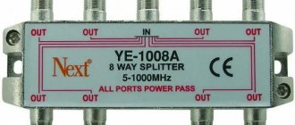
— Distribution allows you to send a signal from one source to many receivers at once. The operation of a signal distributor can be seen in a consumer electronics store, when two dozen televisions show the same video.
Switches and matrix switchers
At its core, a switch is a switch that connects one device to another. For example, the broadcast of an analytical program at the command of the editor in the studio instantly switches to an advertising video. And during a video conference, the switch provides switching between presentation sources (speakers) and allows you to display one or another image on the main screen. Matrix switchers are used for multi-signal switching and are characterized by a large number of inputs and outputs and rich settings. The main property of a matrix switcher is the ability to switch a signal from any of its “inputs” to one, several or all “outputs” of the switch. Matrix switchers can be used in security systems, home theaters, studios, professional display systems, etc.
Control systems
Control systems are designed to control other equipment. There are two components here: user interface devices, such as keypads or touch screens, and controllers. Using buttons, tablets and interactive screens, the user can control the operation of the equipment. For example, lower the projection screen, close the curtains and turn on the projector. Controllers are responsible for directly distributing control signals to the corresponding devices. It is the controller that initiates, for example, the switching of signal sources by the switch, described above. Powerful controllers are capable of managing a wide variety of equipment and can have dozens of I/O ports: Ethernet, infrared, RS-232, USB and other control protocols.
Format converters
This category of switching equipment includes devices that convert one type of signal into another, as well as extract certain components from the signal. The format converter is used to convert an analog VGA signal to digital DVI or digital SDI to component YUV, to change the scan frequency of the video signal, to add audio to the video (embedding) or, conversely, to extract audio from it (de-embedding).
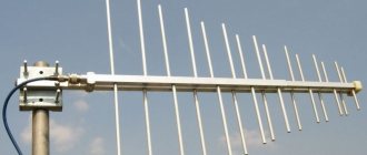
Interface extenders, repeaters
A class of devices designed to increase signal transmission distance. It is known, for example, that the maximum length of the VGA interface cable is 15 meters, for a component signal it is only 5 meters. Increasing the transmission distance is achieved by installing a pair of devices – a transmitter and a receiver. The transmitter takes an input signal (VGA, composite video, YUV, etc.) and outputs it through an interface that allows longer lines, say twisted pair. Accordingly, the receiver performs the inverse conversion. In addition to extending the transmission distance, interface extenders allow you to use existing communications infrastructure to transmit control signals, such as transmitting control signals for conference equipment over a telephone line.
— Repeaters simply repeat the signal, “updating” its power in the line.
Scalers
Scalers are equipment that changes the resolution of the input signal before redirecting it to the output port. For example, a scaler can take a composite video signal as an input and convert it into an output signal in VGA, XGA, SXGA and higher resolutions. When a scaler is equipped with multiple inputs, it is called multi-window. The device combines video signals from multiple inputs into a single image, accordingly scaling the resolution of each source video, and sends the resulting video to the output port. As with a regular scaler, the types of input and output ports may vary depending on the specific device model.
The secondary function of scalers is scan conversion when moving, for example, from a DVI signal to an analog PAL or NTSC. Scalers are widely used in conferencing and presentation systems, as well as in security systems and for combining many “different-sized” video broadcasts on one screen.
Special AV devices
— Galvanic isolation devices allow you to completely eliminate direct electrical communication between devices. Galvanic isolation is used to eliminate interference and to protect equipment and people from high currents.
— Hubs are used to expand the standard I/O capabilities of the system. For example, a USB hub allows you to connect additional USB devices.
— Test signal generators are used to configure video equipment. The generator sends test patterns, dynamic test images, reference signals and other data onto the line, allowing the operator to fine-tune the image output devices.
— Hardware encoders and decoders are designed to convert a signal from the original format (for example, HDMI) into a format suitable for transmission over communication channels (for example, over a local network), and back. Such switching equipment is widely used in Digital Signage advertising systems.
— EDID emulators allow you to retain information about the capabilities of the display when transmitting a video signal over protocols in which this information would be lost, or when combining multiple video signals into one.