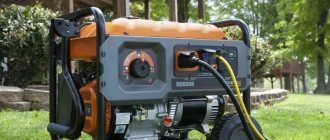
Don't want to buy an antenna for the DVB-T2 terrestrial standard? We'll tell you how to quickly make a homemade one from scrap materials.
It is not at all necessary to buy antennas suitable for terrestrial digital television of the DVB-T2 standard, especially since the cost of the device together with a digital receiver can amount to a decent amount. Moreover, such an antenna must be suitable for the parameters of the frequency range that is used in the area where you live. Otherwise, the multiplex used in the antenna will not receive all available TV channels.
We will tell you how to find out the frequency range of your region and calculate the parameters of the desired antenna. Also, our step-by-step instructions will help you quickly make a high-quality antenna from scrap materials for receiving over-the-air channels of the new digital standard DVB-T2.
For reference:
Multiplex (from the English multiplex - mixture, mixed; also mux) - combining television channels into a single digital package for digital television broadcasting
So, the first thing you need to do is visit the website - map.rtrs.rf
0
Source:
Enter your locality in the search bar. Then look for the closest tower to your location. We left-click on this tower and a plate appears with the frequencies of the air packets. We broadcast two packages of digital channels: RTRS-1 and RTRS-2, 10 channels each. We look at the frequencies and in order to receive both of these packets, you need to take the middle between these frequencies. For example, if the first packet has a broadcast frequency of 700 MHz, and the second 500 MHz, then choose the middle - 600 MHz. Nothing complicated. We have learned to determine the required frequency, now we need to find the wavelength. It is calculated by the formula: Wavelength = Speed of light / frequency. The speed of light is 300 mm/s. We divide this value by the frequency: 300 / 582 = 0.52 That is, the wavelength for a frequency of 582 MHz is 0.52 meters. This is the value we will need to make the antenna. The middle of my gap between the packets, you calculate your length.
Types of TV antennas
A television antenna is a device specifically designed for receiving broadcast television signals that are transmitted at frequencies from 41 to 250 MHz in the VHF range, and from 470 to 960 MHz in the UHF group.
There are two types of television antennas:
- Internal - located on top or next to the TV;
- External - installed on the roof or attic of the house.
Outdoor antennas are more complex to manufacture and install, but such devices are necessary for adequate reception in peripheral areas remote from television stations.
Antenna devices are also divided into:
- Active, which are complemented by an amplifier and require connection to an electrical power source;
- Passive, which amplify the signal only due to design features.
An outdoor TV antenna is a high input power device and has a unidirectional radiation intensity so its far end must always face the broadcast station.
Based on the wavelength that television antennas are capable of receiving, they are divided into three groups:
- MV antennas - such devices receive very long meter waves, the size of which can be from 0.5 to 1.5 m;
- UHF antennas - these devices operate in the decimeter range, in which the wavelength is in the range from 15 to 40 cm. It is in this coverage that digital television (DTV) is supplied;
- Broadband antennas are a hybrid design in which both VHF and UHF elements are installed. Such radio installations are used to receive digital and analogue broadcasts simultaneously.
The most commonly used design is an outdoor television antenna based on a log-periodic dipole matrix. Such products consist of several half-wave elements consisting of metal rods. They act as resonators in which energy is stored by radio waves, which cause electrons to move and create stable waves of oscillatory voltage. An antenna can have a different number of rod elements: the more, the higher its gain.
Another popular design, used primarily for UHF reception, is the reflective TV antenna. Such a device consists of a vertical metal screen with several dipole elements installed in front of it.
The television broadcast bands that must be covered by a single antenna are too wide in frequency, so either separate antennas or combined devices are used for the VHF and UHF bands. In such designs there are two types of elements: long elements that pick up the MF (these are located at the rear of the antenna boom and often function as a log-periodic antenna) and short elements that pick up the UHF broadcast (these are located at the front of the boom).
When you listen to the radio, you notice that local channels can be easily tuned in the FM or VHF range, but you won’t be able to catch distant foreign broadcasts on them; to do this, the receiver needs to be switched to MF and HF mode.
This suggests that meter, medium and short waves are well transmitted over long distances, while ultrashort and decimeter signals have a small coverage area. However, the disadvantage of the UHF range in which our digital television operates is minimized thanks to two things:
- Firstly, the presence of a large number of towers;
- Secondly, the ability of large objects to reflect the signal.
If you live in a private house next to a high-rise building, then it is more correct to point the TV antenna not at a distant tower, but at a neighboring house, which perfectly reflects the waves. The correct choice of direction largely determines the quality of the TV signal.
First DIY antenna: whip
0
Source:
This is definitely the simplest antenna. Essentially it is a piece of wire, 1/4 wavelength long. We take a piece of cable and protect its end under the plug.
0
Source:
We put on and screw the plug.
0
Source:
Remove the insulation from the piece.
0
Source:
Then we remove the shielded layer. We bend it to the transition and use a ruler to measure 12.8 cm (1/4 wavelength) and cut off the excess. The antenna is ready! You can insert it into your TV or set-top box and use it.
All-wave antenna
A TV antenna can have different shapes. For example, from copper wire with a diameter of 2-5 mm, you can build an all-wave antenna in the form of two versatile elements. Such devices are frequency independent, so they are very popular among summer residents. A CHNA device can be built in literally an hour and receive a good signal level far from television centers.
For this you will need:
- Enameled copper wire;
- 2 metal structures in the shape of an isosceles triangle;
- 2 wooden or plastic slats.
Instead of metal triangles, you can use elastic foil laminate, from which you will need to cut the triangles (or leave the copper coating in a triangular shape).
The width and height of the antenna must be identical. The blades are installed at right angles and fixed with a soldering iron. The CNA antenna cable must be laid to the point of zero potential, which is located at the intersection of the cable with the vertical guide. Moreover, it must be tied with a tie, and not soldered.
The distance between adjacent wire threads should be 25-30 mm, and between the plates - no more than 10 mm. It is better to install the antenna structure inside the window at 150 cm. The signal catcher in the form of two expanded elements, which you just made yourself, will confidently receive all UHF and HF channels. If you live in an area with poor signal levels, it would be advisable to supplement such a device with an amplifier.
Second antenna option for DVB-T/T2: Lavalier
0
Source:
It's not difficult to do either. We expose the cable on one side at a distance of approximately 5 cm. We remove the top insulation and insulation from the inner core.
0
Source:
We connect and twist the shielded layer with the core.
0
Source:
Next, we measure 52 cm from the beginning of this connection and remove the insulation to about 0.5 cm of the screen (you can first put on heat shrink).
0
Source:
We close the exposed end to this cut by twisting the core onto it.
0
Source:
Exactly in the center we remove a centimeter layer of insulation with a shielded layer. This can be done conveniently with a stationery knife. The plug was screwed in advance. The antenna can now be used.
Manufacturing and arrangement
Today, all television is presented in digital format; analogue will soon be completely abandoned. Old antennas practically do not function with DVB signals, so you need to create a decimeter antenna.
Digital TV transmission in DVB-T2 format is carried out in the UHF range, and since the signal is broadcast digitally, its reception will always be in good quality, or it simply cannot be caught, and there will be no signal at all. Interference, distortion or unclear picture - this is typical only for analog television.
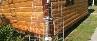
DVB (Digital Video Broadcasting) encoding is insensitive to electromagnetic interference, however, if the air is heavily polluted, signal mismatch may occur, which can cause the image to freeze or completely crumble. Therefore, it is more efficient to place the antenna outside the house: outside the window, on the roof, on the balcony.
To reduce the amount of interference, a reflector (reflector) can be built behind the antenna. The simplest materials with a metallic tint are suitable for the antenna design: foil, coffee or juice packaging, tin can, CD, etc. In order for the reflector to have a narrowly targeted effect, the shape of the reflector can be made parabolic. Although this is more relevant for analog receivers, reflectors also help out when the digital signal level is weak.
And the last piece of advice: experienced engineers recommend soldering all antenna connections, and not just twisting or screwing them, as over time they will oxidize and affect the quality of reception. It is better to coat external antennas made by yourself with paint; it will more reliably protect your structure from adverse weather factors.
To connect antenna elements, it is better to use soldering machines with a power of 36-40 watts, flux and soft solders.
Settings
Installation of do-it-yourself products is carried out similarly to factory-made analogues. Most options require a mast to raise them to maximum height.
In most cases, a height of 2-3 meters higher than the height of the roof of the building is sufficient. Additionally, when installing, you should choose a place with the strongest signal, this is especially true for indoor devices.
Configuration is carried out by rearranging or rotating the antenna towards the tower; sometimes it is necessary to install an additional screen on the rear side.
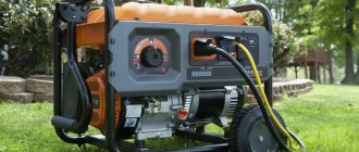
Do you need an antenna amplifier?
The question of purchasing an antenna amplifier arises when signal loss becomes systemic.
Due to insufficient transmission, the receiver or digital tuner cannot cope with the processing of the organization. You may see a “no signal” or “weak signal” message on the TV screen.
If communication is carried out without an electronic intermediary, then signal loss can be expressed by the absence of sound, a “freezing” image, an unclear or “pixelated” picture
If the signal is too weak, an antenna amplifier is installed, the main purpose of which is to make the signal more powerful. It is integrated into the TV system on the section of the route between the television receiver and the antenna.
Most often, external devices are used that cut into the antenna cable using two connectors. More “serious” amplifiers look like a set-top box, and some have an additional power supply
Active type antennas already have built-in amplifiers; installing a second one will not help. Also, it will not cope with its function if the antenna is broken or, due to its parameters, is simply not able to receive a signal at a long distance.
In the area of stable reception, the amplifier can even cause harm, since too powerful a signal is also one of the reasons for the failure of the digital tuner.
How to make your own antenna for digital TV
Any TV signal is transmitted in space from the broadcast towers to the TV receiver by an electromagnetic wave in the form of a sine wave, which has a high frequency. When a wave passes through the surface of the antenna beams, a voltage V is established in it. Each sinusoidal half-wave creates a potential difference with a certain sign.
Under the influence of a set voltage, which is applied to a closed antenna circuit of the input signal with resistance R, an electric current flows in the signal. The TV circuitry carries out its amplification and processing, as a result of which a picture is displayed on the screen and audio is output to the speakers.
The receiver design must meet the following requirements:
- Made carefully, with a high degree of precision, which eliminates loss of signal electrical power.
- The direction is strictly along the axis of the electromagnetic wave that comes from the transmitter.
- Orientation by polarization type.
- Protection from external interference of the same frequency. Interference may come from generators, radio towers, electric motors, or other similar equipment.
Results
Concluding the topic, you should pay attention to the fact that the highest quality of reception can be achieved by using soldering (bolts and nuts oxidize, significantly deteriorating the signal). An important aspect is the correct choice of cable. The most popular option is a product with a resistance of 75 Ohms, made of silicone.
Such products have a long service life, plus they are not affected by climate. The way you connect the cable to your TV is important. It is recommended to use special plugs; solderless options are allowed.
Before starting to assemble the product, you need to decide on the type of product; to do this, you should find out the frequency at which the signal is broadcast, this depends on the specific area.
Despite the rapid development of satellite and cable television, the reception of terrestrial television broadcasts still remains relevant, for example, for places of seasonal residence. It is not at all necessary to buy a finished product for this purpose; a home UHF antenna can be assembled with your own hands. Before moving on to considering the designs, we will briefly explain why this particular range of the television signal was chosen.
What can such an antenna do?
It is quite difficult to implement a high-quality unidirectional antenna without special tools and skills, so the antenna will be classified as low-power. Homemade products can be useful in the following cases:
- Short range to the repeater. The distance limit to the radio station is 15-20 km.
- There are no obstacles in the direct line of sight to the repeater in the form of buildings or forest belts.
- The signal itself is picked up by the receiver. The main thing is that the latter is not in the dead zone.
You can check the signal level using various methods. The easiest way is to use the options of advanced digital TVs.
The test usually proceeds according to the principle:
- Turn on the TV and instead of video, open Settings . An antenna is not needed at this stage.
- Find the signal strength indicator in the parameters.
- This indicator should indicate the signal strength. If it is more than 15%, digital TV can be caught on homemade TV. If less, then you need to connect a more powerful device.
Beer can antenna
Ether antenna devices can be created from many simple materials that are used in household use, even from ordinary cans in which carbonated drinks are sold. Such a mini-receiver will not be very powerful, but you can pick up about 7 channels, not only in the UHF range, but also in the longer one - VHF.
There is one important condition: the cans must be smooth, not ridged, clean and dry. The essence of this design is very simple: you just need to solder 2 cans to the cable and place them on opposite sides on a wooden base.
The number of cans can be used differently; it is believed that it is optimal to create 3 or 4 lines of cans, since 1-2 lines pick up the signal weakly, and more than 5 lines are difficult to coordinate. In addition to cans, you need to prepare the following materials:
- About 5 meters of ordinary TV cable marked “RK-75”;
- Wooden or plastic base structure;
- Several self-tapping screws, electrical tape, and a soldering iron.
First you need to prepare the TV cable: step back 10 cm from the edge, make a shallow cut and remove the top layer of insulation. Carefully twist the inner braided screen into a single bundle. On the same side of the cable, remove the plastic insulation and expose the central core. A plug must be connected to the opposite end of the cable.
Next, we will need to connect the coaxial cable to the banks. To do this, it is better to use small flea screws for drywall: screw a twisted cable braid to one can, and a copper core to the second can. For better contact, connections can be soldered.
Now you should secure the cans to a wooden base plate. This can be done using ordinary adhesive tape, electrical tape or a glue gun; you can even use an ordinary clothes hanger or any flat structure at hand. The main thing is that the metal cans are of the same shape, the same size (volume) and are located strictly on the same line. The distance between the sheet metal elements, as well as the location of the antenna installation, is selected experimentally.
You can improve the design by creating a grid of several lines with banks, and if there is such an opportunity, then connect an amplifier. If a homemade antenna made from beer cans is placed on the street, then its elements will have to be hidden in larger plastic bottles.
The length of the cable affects the signal attenuation: the longer the cord, the more the on-air transmission is attenuated. This is especially true for receiving meter waves.
Varieties
"Beer"
To make the product you will need an even number of beer cans. The most common options are made of two pieces. The installation process is quite simple and requires a minimum of tools and consumables.
Instructions:
- To begin with, take a wooden strip (a hanger will also do), which will serve as a support for the structure.
- Beer cans are attached to the rail using tape , at a distance of about 6 centimeters.
- Next, a television cable is attached to the banks. The procedure can be performed using either self-tapping screws or solder.
- The last step is to attach the base to the mast and adjust the position. A more complex version is made from 6-8 cans. Such an antenna will require two bases installed vertically.
- 4 cans are attached to the installed bases, parallel to each other.
- Using a copper plate or wire, you should connect the cans located on one rack, then perform the procedure on the other.
- The next step is to install the racks into one structure ; it should be taken into account that the distance between the bottoms of the cans must be at least 60 mm.
- It remains to secure the cable at the extreme points of the connecting plates.
Antenna with minimal costs
It should be remembered that television travels in space in the form of waves that are well perceived by metal objects. To watch several TV channels, you can use a piece of wire, one end of which is attached to the heating system, and the other into the TV to the central contact.
Read also: How to connect an Indesit electric stove
The principle of operation of such an antenna is based on the area of the system, and it envelops almost the entire house at different heights. The reception quality of the design is not the highest. A more interesting option requires a balcony with metal strings for laundry.
The assembly technology is completely similar to the battery system. There are places with reliable signal reception, where you can use a knitting needle, which will make it possible to view the main channels.
Regular antenna
Assembling the antenna yourself is quite simple; you will need a tube made of aluminum or brass. The latter option is more convenient, since this material practically does not oxidize.
Instructions:
- The length of the tubes should be 276 mm - this is what ensures the reception of most channels; the thickness is 20 mm. The tubes should be flattened on one side, then holes should be drilled in these places.
- The next stage is preparing the base. It must be made of dielectric material, measuring 150 by 50 mm and at least 5 mm thick.
- Next, a mock-up of the antenna is laid out on a flat surface. The base is laid, the tubes are placed on top of it, the distance between the flattened ends of the tubes is 65 mm, the locations of the holes in the tubes are marked and a hole is made in the base with a drill of the same diameter.
- The next stage is the assembly of the structure. The tubes are attached to the base using bolts; it is advisable to use an additional fastening in the form of a clamp - this will ensure the strength of the structure. The bolts used for fastening are 15-20 mm long, this is necessary for fastening the loop.
- The antenna assembly is complete , all that remains is to connect the cable; this cannot be done directly to the antenna. The correct connection is made through a ring of wire with a resistance of 75 ohms. The length of the loop is calculated individually depending on the length of the tube; in this situation it is 280 centimeters.
The outlet cable is already connected to the loop.
Powerful antenna
Having dealt with the classic options, you should consider antennas designed to receive the weakest signal. To create one, you will need a minimum of materials, namely a brass tube, a plate of the same material, desire and hands.
Instructions:
- The manufacture of the receiving device begins with bending two squares of the same size from the tube , attached to a dielectric base in such a way that the distance between the corners of the squares is 10-15 mm.
- The next step is making a screen designed to enhance the signal power and smooth out radio interference. The screen is curved in the shape of a rectangle 11x10 centimeters, with a side height of 23 mm and a width of 6 mm.
- When connecting two components, a distance of 12 mm must be maintained. The finished product is connected to the TV using a cable with a resistance of 75 Ohms. An important fact is that this design does not allow the use of bolted connections, only solder is allowed.
UHF antenna
Digital television is covering more and more territories, but for its reliable reception a special module is required. Often, the device is purchased separately, but there are TVs that have a built-in module.
But one receiver is not enough; you need an antenna that receives UHF waves. The simplest option is made on a sheet of plywood.
Instructions:
- For assembly you will need a 75 Ohm television cable 53 cm long. This section is fixed on a sheet in the shape of a ring; it can be secured either with clamps or with glue.
- When bending the loop, make sure that there is a gap of 5-10 mm between the ends of the cable. The second element of the product is made from a similar cable, 15.5 cm long, from which a loop is made.
- The connection between the ring and the loop is carried out as follows - the inner core of the ring is connected to the winding of both sides. The loop of the central conductor is attached to this twist, and the outer winding is connected between the edges. The central core of the antenna cable is connected to the inner core of the loop, and the winding is connected to the loop winding.
Log-periodic circuit
A log-periodic antenna prepared for use is structurally much more complex than equipment sold in stores:
- The axle rod separately supplies power to the antennae. This allows the signal to be received synchronously.
- The signal conductor to the TV is a coaxial wire connected to the beginning of the rod.
- The antennae from top to base must be synchronously removed from each other at each step.
You can make the base yourself or buy it in a store. In the 2nd case, it is worth using “delta” type equipment in the form of a “herringbone”, replacing the plane of the reflector grating. To assemble the base yourself, you can use a soldering iron. Connect the rods, then cut them to the desired length.
The antennae can also be connected with copper wire. In order for them to be firmly attached to the rod, you need to attach the entire structure to the board. The antenna will look less aesthetically pleasing, but will receive good protection from precipitation.
Below you can see the characteristics of a 10 dB log periodic device:
- rod size – 1.6 m;
- number of antennae – 9;
- index of reduction in the size of the next pair of antennae from the base - 160 mm;
- the difference between input and output resistance is 20 Ohms.
As a result, you will get a receiver operating in the frequency range 460-790 MHz. Connect the rods together, and then ground the structure. For this you can use a copper cable.
After making the log-periodic device, set it up. Take 2 load-bearing elements and move them without moving them away from each other. The antennae should be parallel. Make adjustments until a picture appears on the TV.