Specifications:
Measurement accuracy:
— 0.1 °C — ranging from -9.9 to +99.9 °C — 1 °C ranging from -50 to -10 and from +100 to +110 Control accuracy: — 0.1 °C — ranging from - 9.9 to +99.9 °C - 1 °C between -50 to -10 and +100 to +110 °C Hysteresis: 0.1 to 15 °C Hysteresis accuracy: 0.1 °C Update rate: 0.5 seconds . Circuit supply voltage: DC 12V (DC12V). Power consumption: static current: 35mA; current with relay closed: 65mA Thermistor: NTC (10K +-0.5%). The length of the sensor extension is 50 cm. Output: 1 channel relay output, power = 10A Humidity 20% -85% Size: 48 * 40 * 14 mm.
Poll: Have you ever made anything with your own hands? (Number of votes: 2080)
Yes, a lot of things
Yes, it happened once
No, I’m still researching it in order to make it
No, I am not going
To vote, click on the desired answer. results
General instructions: Digital two-threshold, two-mode, frameless, powered 12V temperature controller XH-W1209 is designed to maintain the required air temperature in incubators, greenhouses, terrariums, heating systems, to control the temperature of heated floors, swimming pools, freezers, systems to prevent drains from freezing, etc.
The thermostat is controlled by an STM8S003F3P6 microcontroller, which analyzes the temperature measured by a digital sensor, compares it with the set value, takes into account the specified operating mode, and based on this data turns on and off the load. Switching is carried out by an electromagnetic relay.
The thermostat is contact (the thermostat uses a relay power element). Two-threshold thermostat - upper and lower thresholds (possibility of setting the upper value (threshold) of the on (off) temperature and the lower value (threshold) of the on (off) temperature.
Description of the device: 3 control buttons: set, +, — . set - selects the installation mode and parameter settings + and - change the value of the installation and parameters
In mode C (cooling) it works like this:
while the temperature is below the set point, the relay contacts are open; when the set temperature is reached, the relay contacts close and remain in this position until the temperature decreases by the amount of the set hysteresis (by default, 2ºC). In H mode (heating) it works the other way around
If you press the “SET” button, then using the “+” and “-” buttons you can set the relay switching temperature (if the current temperature is BELOW this value, the contacts of the power terminals are closed.) The thermostat must work in tandem with a heater or cooler.
To set the control temperature, you must press the SET button, then use the “+” or “-” buttons to set a new temperature, and press the SET button again.
To enter the programming mode, you must hold the SET button for 5 seconds, then use the “+” or “-” buttons to select a menu item from the list below. To save the settings, you need to press and hold the SET button, or do not press any buttons for 10 seconds. To return to the default settings, press and hold the “+” button.
Module overview
Thermostat W1209 is a programmable temperature control relay. The supplied sensor is operational in the temperature range from -50°C to +110°C. The regulator is designed to work with heating and cooling equipment with a power of up to 1 kVA.
Technical characteristics of the w1209 thermostat:
- Controlled temperature range – -50°C – +110°C;
- Measurement accuracy in the range from 9.9°С to 99.9°С – 0.1°С, above the range – 1°С;
- Control accuracy in the range from 9.9°С to 99.9°С – 0.1°С, above the range – 1°С;
- Hysteresis setting – from 0.1°C to 30°C;
- Control current (load) = 14V – 20A, ≈220V – 10A;
- Supply voltage – 12V;
- Current consumption – 22-72 mA;
- Overall dimensions – 48x40x14 mm;
- Weight – 20 g;
- Permissible operating temperature – -10°C – +60°C.
Note! Some sellers position this device with the name xh w1209. All devices of this type are absolutely identical.
Operation of W1209 using the example of connecting to an incubator
The connection diagram for the thermostat here is almost the same as described above, only the following are added to the heating elements: a cooling fan, a 12-volt adapter, a fan, a heating element - incandescent light bulbs.
The figure below shows the diagram by which the incubator is connected. The wires of all electrical appliances are connected to the W1209 thermostat. Let's start with the arrival of alternating voltage.
On the right side you can see the block connecting the thermostat to a 220 volt DC network. However, it is not connected directly, but through a 12-volt adapter that converts 220 to 12 volts. This adapter connects to the two right slots - “minus” and “plus”.
In addition, a 12 volt fan is connected to the same wires. Incandescent lamps are connected to the two left slots. Please note that the light bulbs are connected directly to the network without transformers.
The thermostat itself has a mode in which, if the normal temperature rises, the circuit opens automatically and the lights go out. The lamps themselves are connected in parallel so that more powerful incandescent light bulbs can be screwed in and they can also operate at only half their capacity.
The W1209 temperature sensor is not made in the best way, because the length of its wires does not exceed 50 centimeters. In most cases, this is not at all sufficient for the correct installation of the device in order to correctly measure temperature.
Setting up and operating the thermostat
Installing the W1209 programmable thermostat involves connecting the device to a stabilized power source, setting up the temperature sensor and the controlled circuit.
Important! The fundamental point is that the device contains only “dry” relay contacts, that is, it switches the circuit and does not supply any power to the line.
To operate the device correctly, you should know the features of its operation:
- It is possible to delay the start from 0 to 10 minutes;
- The circuit has adjustable hysteresis. Hysteresis is the temperature difference between switching on and switching off. This function is important for switching heating or cooling devices with high inertia.
Further setup consists of selecting the required parameters using the control buttons and LED digital indicator.
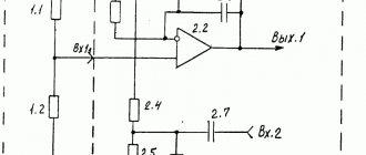
The instructions for the w1209 thermostat under consideration do not provide a detailed description of the circuitry, but enthusiasts have drawn up a circuit diagram of the w1209 with 12 V DC power supply, from which it is clear that the operation is controlled by a programmable microcontroller connected according to a standard circuit.
Do-it-yourself modernization and modification of the W1209 thermostat module
On the board, the RESET input (4 pin of the controller) is connected to programming contacts and the controller is sometimes falsely reset due to strong spark noise (the relay is installed on the board).
Programming Contacts
This was eliminated by installing a capacitor with a capacity of ~0.1 µF on the common wire. The SMD capacitor was simply soldered to the spots. Look at the photo.
Capacitor installed
I finalized the board. I want to warn you right away that there is a chance of damaging the module. I carried out the work with my own hands at my own peril and risk. To eliminate installation problems, the following were removed from the board: the temperature sensor connector, terminals and relays. Unfortunately, the module is assembled on a machine, which means that the parts are tightly installed in the holes of the board. It is not possible to remove all the solder using suction. When dismantling the relay, unfortunately the board tracks were damaged (restored with conductors).
Removing parts W1209
The sensor connector was soldered on the back of the board. I also soldered the terminals on the back side of the board. See photos and videos.
Parts installed and removed
I soldered the conductors from the relay coil power paths to the relay contact terminal tracks. The relay was connected to another type “C” with changeover contacts. The relay coil was connected to the module with two extension conductors through the terminals.
Relay module W1209
In this form, the top of the board will not interfere with the integration of the module into the device. I purchased the relay from the store using this link . It is useful to check the accuracy of the readings, read about this below.
Setting procedure
Please read the instruction manual before turning on.
To control the settings, the W 1209 circuit provides three buttons:
All provided functions and capabilities are configured by clicking on the listed buttons.
According to the instructions for W1209, to change settings you must enter programming mode. To do this, press and hold the “Set” button for 5 seconds. When the number of the setting item is displayed on the screen, the button can be released. To navigate through the settings menu, use the “+” and “-” buttons.
In total, the instructions for the W 1209 thermostat provide from 6 to 8 positions, depending on the current firmware of the built-in microcontroller:
- P0 – switching heating or cooling control;
- P1 – adjustment of the hysteresis range;
- P2 – change in the maximum temperature control limit;
- P3 – change the minimum temperature control limit;
- P4 – correction of temperature measurement error;
- P5 – programming the turn-on delay time;
- P6 – alarm (not used in most firmware);
- P7 – forced shutdown when the upper control threshold is reached;
- P8 – reset to factory settings (does not work on all firmware).
By default, when entering the programming mode, the first menu item is set to P0.
Having entered the desired item, use the “+” or “-” buttons to set the required parameter value. To exit the programming mode, press and hold the “Set” button for 5 seconds. Entering the operating mode with recording settings also occurs after 10 seconds, if no button was pressed during this time.
The instruction for the w1209 dc 12 V thermal relay informs that this device has an alarm for incorrect operation, which is displayed on the indicator:
- LLL – temperature sensor break;
- 110 or HHH – short circuit of the sensor loop;
- 888 – sensor malfunction.
In addition to using the programming mode, a factory reset can be performed as follows:
- Remove power from the regulator;
- Press the “+” and “-” buttons simultaneously;
- Turn on the power.
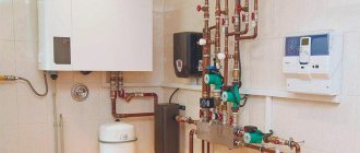
How does a gas boiler room thermostat work?
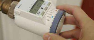
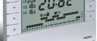
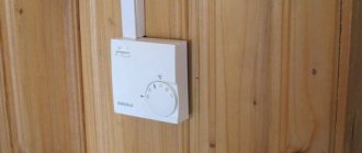
A protective film is visible on the thermostat display.
The current room temperature and the temperature set by the setting are displayed. Sun - work in a programmable mode in the “Sunday afternoon” interval. Snowflake - Frost protection function is enabled. At the bottom of the screen is the current time and day of the week - Sunday. installed in the room , with temperature control by hysteresis , measures the current air temperature and, if the temperature drops from the value set in the settings, turns the boiler on. For example, if the temperature is set to 22 °C in the thermostat setting, then the boiler will turn on, taking into account the hysteresis +/- 0.5 °C, when the air temperature drops to 21.5 °C. The heating water heated by the boiler will begin to flow into the radiators and heat them. The radiators, in turn, will heat the air in the room.
The problem is that the process of heat transfer from radiators to the room air is very slow. After turning on the boiler, the air temperature in the room, at the place where the thermostat is installed, will continue to decrease for some time, to 21 °C, and only after that will begin to increase. When the air temperature increases to 22.5 °C, the thermostat will turn off the boiler. But from the heated radiators, the air temperature in the room will continue to increase for some time, up to 23 ° C.
Due to the presence of a large time delay in the feedback loop, fluctuations in the air temperature in the room will be noticeably greater than the value of the thermostat hysteresis. Fluctuations in the air temperature in the room will be +/- 1 °C from the specified 22 °C.
Often the temperature of the heating water manages to increase to the maximum at which the boiler will disconnect from the boiler temperature sensor. Although the thermostat will still command the boiler to turn on.
Calibration of thermal relay W1209
Thermal relay calibration is carried out in programming mode in menu item P4. For calibration you need to have a reference thermometer. Comparing the readings of the standard with the readings of the design, they are brought to the same values by manipulating the “+” or “-” buttons. After exiting the settings, W1209 automatically adjusts the measurement temperature over the entire range.
If you don’t have a thermometer, you can use the known values:
- Snow melting temperature – 0°C;
- The boiling point of water is 100°C.
Important! To reduce errors during the calibration process, it is necessary to use distilled water.
For domestic use, the error will be within acceptable limits when calibrated using boiled water instead of distilled water.
Basic elements of a refrigerator temperature sensor
In household refrigerators, thermostats of various designs are used, but their individual elements perform very specific functions that are the same for all designs.
The abrupt contact opening unit protects the thermostat contacts from burning when opened. In the above schematic diagram of the thermostat, for the purpose of simplicity, the movable contact is placed on the power lever, which is directly acted upon by the bellows and the main spring. With this arrangement of the moving contact, severe burning of the contacts and their rapid failure are inevitable. This is explained by the fact that the rupture of the electrical circuit when the contacts are opened will occur slowly in accordance with the movement of the lever, which, in turn, is determined by the slow change in temperature and, accordingly, freon vapor pressure in the heat-sensitive system.
In addition, with such an arrangement of the moving contact, a slight turn of the power lever will immediately open or close the contacts, i.e. break the chain frequently. The abrupt contact opening unit eliminates these shortcomings. In this case, the moving contact is located on another lever (plate), connected to the power lever by a special reversible spring. When the power lever is rotated to certain positions, the lever with the contact will remain motionless, and then the flip spring will sharply change its position and the contacts will sharply open (or close).
The temperature change unit is a device that changes the tension of the main spring. In some thermostats, the spring tension is changed by rotating a screw, which moves a nut that rests on the end of the spring; in others, by rotating a roller with a profile cam pressed onto it, acting on the spring. The screw (roller) is rotated with a handle that has a pointer for setting it to a certain position on the instrument scale.
A temperature-sensitive system is a sensor that responds to changes in temperature in a controlled object and acts on the contact system of the device.
The final part of the tube, sensitive to temperature changes, may differ slightly for different thermostats, which depends mainly on the level of the liquid phase of freon in it. With a small inner diameter of the tube or a relatively large amount of freon in the tube, when the level of its liquid phase exceeds 80...100 mm, it is difficult to ensure a tight fit of the tube to the evaporator wall at such a length. In these cases, the end of the tube is curled into a spiral, bent into an elbow, or a can with an internal diameter larger than that of the tube is soldered.
The differential adjustment unit is used to regulate the differential value. The thermostat differential is the difference between the opening and closing temperatures of the contacts (at a certain tension of the main spring). The smaller the differential value of the device, the more within narrow limits the set temperature will be maintained. In thermostats of household refrigerators, this unit is used only for factory installation of the device. In many designs it is missing.
The differential is changed using a screw, which, being a limiter for the movement of the power lever, brings closer or removes the moment when the flip spring throws the lever with a moving contact.
The semi-automatic evaporator defrosting unit creates convenience when removing snow cover. The unit is used in individual designs of thermostats. The principle of its operation and design depend on the method of removing snow cover adopted in a particular refrigerator.
The principle of programming a thermostat for heated floors
Any thermostat, even programmable, has a manual mode. That is, a comfortable temperature is set and the thermostat maintains it: turning off when the set temperature is reached and turning on when it cools down. The thermostat determines the temperature in two ways:
- from an air sensor installed in its own housing;
- from a remote sensor installed in a warm floor, usually placed in a corrugation as close as possible to the heating element.
The problem of energy saving is solved by setting time intervals for the controller operation. Why waste the floor heating if no one is home? On the indicators, the manual mode is indicated by a hand symbol, and the automatic or programmed mode is indicated by a stylized clock. In most cases, the idea of the program is the same, the only differences are in the method of transferring this toy into programming mode.
The first thing that confuses a responsible buyer is the discrepancies in the descriptions of technical parameters. For example, there are two descriptions for the same regulator: “6 programmable time periods” or “7-day programming function for energy saving.” What is what? It's impossible to guess.
The main programming task is to determine the time the thermostat turns on and off. At first, it seems that there are a lot of time periods and you can get confused. But all manufacturers have approximately the same idea of programming in time periods. The developers share three weekly programs:
- Weekdays from Monday to Friday + two days off - Saturday and Sunday;
- Working week from Monday to Saturday + day off – Sunday;
- Same routine for the whole week.
That is, on weekdays, when normal people are at work, the thermostat turns on three times a day: in the morning, afternoon and evening. On weekends, he works for one time period. The beginning and end of these time periods must be programmed by the user.
Events when the heated floor should be turned on or off are indicated by the following stylized icons: the sun rose, went to work, came for lunch, went to work again, came home in the evening, the moon rose - everyone goes to bed.
When purchasing a thermostat, there is a default program. If you are satisfied with the turn-on time and the five-day work week, then all that remains is to adjust the comfortable temperature.
Factory settings for temperature and time intervals
| time interval | symbol | time | temperature |
| Mon-Fri | 1 | 6:00 | 20 |
| 2 | 8:00 | 15 | |
| 3 | 11:30 | 15 | |
| 4 | 12:30 | 15 | |
| 5 | 18:00 | 22 | |
| 6 | 22:00 | 15 | |
| Sat-Sun | 1 | 8:00 | 22 |
| 2 | 23:00 | 15 |
Practice of using an electric floor heating thermostat
Our person begins to read the instructions only if he himself could not guess. This is exactly what happened in our case: with the manual mode everything is clear, in the automatic mode we were only able to adjust the temperature. And it seemed that this was how it should be, because “they there” came up with everything so well. Probably, programming consists precisely in setting the temperature, and the daily routine cannot be changed. But in practice this is far from the case.
At first, only the manual mode was used - “I’ll turn it on myself, turn it off myself when necessary.” However, taking care to turn it on in advance and turn it off in time led to the opposite result. In the morning, stepping on the cold tiles, the legendary “damn it!” was said, then the warm floor was heated, and before leaving for work, it was sure to be turned off in order to save money. In the evening the picture repeated itself. A few weeks later, when all thoughts before bed were already focused on the warm floor, at the most crucial moment they forgot to turn it off at night. In the morning the traditional “damn it!” sounded, the floor turned off, and in the evening history repeated itself.
As a result, I had to take the instructions and master this simple device. First of all, set the current time and decide on the weekly work cycle. And only then shift the on-off times at a time convenient for our family.
As practice has shown, default cycles are only suitable for those who have children returning, for example, from school. But when the whole family works, a warm floor is not needed during lunch. But this pitfall can be easily avoided. It is necessary to shift the time of lunch to dinner, and the “third switching on” to the period of time before bedtime. With this arrangement it became really very convenient.
Refrigerator temperature sensor location
The location of the regulator depends on the refrigerator model. Information about its structure and location is contained in the operating instructions for the household appliance. It is usually located next to the temperature control knob. In old household appliances, the thermostat is installed inside the chamber, under the light bulb, and covered with a protective housing. To remove the part, remove the handle by pulling it towards you. Then unscrew the screws and dismantle the housing.
In modern models, the thermostat is located outside, usually above the door. If it needs to be removed, first also remove the adjustment knob. Then unscrew the bolts and remove the panel with the light bulb, after which the regulator is removed.
Operating modes of thermostat E 51.716
Manual mode
The thermostat constantly maintains the user-specified temperature throughout the day. All software settings are disabled.
Program mode
Work according to a given program. It is possible to program 6 time intervals with different temperatures during the day for each day of the week.
Comfort mode
The temperature can be temporarily changed for the current mode. The comfortable temperature returns to the original value in the next event, the thermostat continues to operate according to the previously set program.
- Awakening, event 1.
- Leaving home before lunch, event 2.
- Return for lunch, event 3.
- Leaving home after lunch, event 4.
- Returning home in the evening, event 5.
- Dream, event 6.
Note! When selecting the comfortable heating mode (based on the floor temperature sensor), it is recommended to set the temperature to 28-32°C for comfortable heating and 20-24°C in energy saving mode. In this case, it is necessary to increase the temperature 60-120 minutes before the onset of the event, and lower it 30-60 minutes before the onset of the next event. The settings are adjusted by the user through experience.
General information
The thermostat has a three-digit indicator (HS310281K), which allows you to display the temperature from -50 ºС to +110 ºС. (temperature -10ºС to -50ºС and 100ºС to 110ºС is displayed without decimal place), which is sufficient for domestic use. Also, the board has a red LED “LED1” which duplicates the activation of the relay. The thermostat supports two operating modes “C” (cooling) and “H” (heating), the mode can be changed using three control buttons.
Purpose of the buttons ► “SET” - selecting an operating mode and setting parameters ► “+” - increasing a parameter ► “-” - decreasing a parameter
Example: In operating mode “C” and the set temperature is 25ºC, the relay will operate when the temperature reaches 25ºC and turn off at 23ºC
Technical characteristics of thermostat E 51.716
220 V, 50 Hz
| Voltage | |
| Maximum switching current | 16 A |
| Maximum power | 3520 W |
| Temperature range | +5 °С … +60 °С |
| Temperature range maximum | +5 °C … +90 °C |
| Temperature control step | 0.5 °C … 10 °C (factory setting 1 °C) |
| Thermostat power consumption | 2 W |
| Installation temperature | -5 °С … +50 °С |
| Housing protection level | IP 20 |
| Housing material | High quality self-extinguishing plastic polymer |
| Floor sensor | NTC, 3 m |
| Air sensor | NTC built-in |
| dimensions | 86 x 90 x 46 mm |
| Manufacturer country | China |