Resonance - what is it?
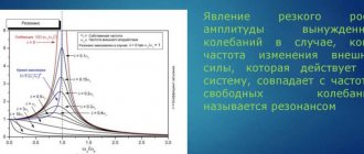
Resonance in physics is the frequency-selective response of a system of oscillations to external forces that periodically act on the system. This effect manifests itself in a sharp increase in the amplitude of the movements of these oscillations, when the frequency of the external acting force coincides with some frequencies characteristic of a given oscillatory system.
Important! The essence of resonance is a sharp increase in the amplitude of vibrations when the frequency value of the force acting on the system from the outside coincides with the natural frequency of vibrations of this system.
Dull and sharp resonance
To further talk about the phenomenon of resonance, you should understand what vibrations and frequency are. Oscillations are a process of changing the states of an oscillatory system, which is repeated at certain intervals and occurs around the equilibrium point. An example is swinging on a swing. Resonance of frequencies can occur only where there are oscillatory movements. Moreover, it does not matter at all what type of vibrations are: electrical, sound, mechanical.
Types of oscillatory movements
The oscillation process is characterized by frequency and amplitude. In simple words, using the example of a swing, we can say that the amplitude is the highest point that it reaches. The oscillation frequency is responsible for the speed at which the swing reaches this point.
Returning to the example of a swing, we can say that when it swings, the oscillation system performs forced oscillations. The amplitude of these oscillations can be increased by influencing this system in a certain way. That is, if you push the swing with a certain force and at a certain time, you can swing it strongly without using much effort.
This phenomenon will be called resonance: the frequency of external influences will coincide with the frequency of oscillations in the system, and as a result, the amplitude will increase.
Voltage resonance in an electrical circuit
Examples of resonance in life
Pushing a person on a swing is a common example of this phenomenon. A loaded swing, a pendulum, has a natural vibration frequency and a resonant frequency that resists being pushed faster or slower.
An example is the oscillation of projectiles on a playground, which acts like a pendulum. A person's push while swinging at a natural swing interval causes the swing to go higher and higher (maximum amplitude), while attempting to swing at a faster or slower pace creates smaller arcs. This is because the energy absorbed by vibrations increases when the shocks correspond to natural vibrations.
The response is widely found in nature and is used in many artificial devices. This is the mechanism by which virtually all sine waves and vibrations are generated. Many of the sounds we hear, such as when hard objects made of metal, glass or wood hit, are caused by short vibrations in the object. Light and other short-wave electromagnetic radiation is created by resonance on the atomic scale, such as electrons in atoms. Other conditions in which the beneficial properties of this phenomenon may apply:
- Timekeeping mechanisms of modern watches, a balance wheel in a mechanical watch and a quartz crystal in a watch.
- Tidal response of the Bay of Fundy.
- Acoustic resonances of musical instruments and the human vocal tract.
- Destruction of a crystal glass under the influence of a musical right tone.
- Frictional idiophones, such as making a glass object (glass, bottle, vase), vibrate when rubbed around its edge with a fingertip.
- The electrical response of tuned circuits in radios and televisions that allow selective reception of radio frequencies.
- Creation of coherent light by optical resonance in a laser cavity.
- Orbital response, exemplified by some of the gas giant moons of the Solar System.
Atomic-scale material resonances are the basis of several spectroscopic techniques that are used in condensed matter physics, for example:
- Electronic spin.
- Mossbauer effect.
- Nuclear magnetic.
Description of the phenomenon
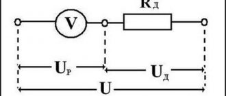
If in a certain electrical circuit (see Fig. 1) there are capacitive and inductive elements that have their own resonant frequencies, then when these frequencies coincide, the amplitude of the oscillations will increase sharply. That is, there is a sharp surge in stress on these elements. This can cause destruction of electrical circuit elements.
Rice. 1. Resonance in an electrical circuit
Let's look at this example to see what phenomena will occur when an alternating current generator is connected to the contacts of the circuit. Note that coils and capacitors have properties that can be compared to the analogue of a reactive resistor. In particular, a choke in an electrical circuit creates inductive reactance. The capacitor causes capacitance.
The inductive element causes a phase shift, characterized by a lag of the current from the voltage by ¼ of a period. Under the action of a capacitor, the current, on the contrary, leads the voltage by ¼ period.
In other words, the effect of inductance is opposite to the effect on the phase shift of capacitance. That is, inductors and capacitive elements influence the generator in different ways and adjust the phase relationships between electric current and voltage in their own way.
The total reactance of the elements we are considering is equal to the sum of the resistances of each of them. Taking into account the opposite actions, we can write: Xtot = XL - Xc, where XL = ωL is the inductive reactance, the expression Xc = 1/ωC is the capacitive reactance.
Figure 2 shows graphs of the dependence of the circuit impedance and the associated current on the reactance of the inductive element. Pay attention to how the total resistance decreases as the reactance RL decreases (graph b) and how the current increases (graph c).
Rice. 2. Graphs of the dependence of current parameters on the drop in reactance
Electrical circuits consisting of series-connected capacitors, passive resistors and inductors are called series resonant (oscillatory) circuits (see Fig. 2). There are also parallel circuits in which R, L, C elements are connected in parallel (Fig. 3).
Rice. 3. Series oscillatory circuit
Rice. 4. Parallel oscillatory circuit
In resonance mode, the power of the power source will be dissipated only through active resistances (including the active resistance of the coil). Resonant circuits are characterized by losses only of active power, which is spent to maintain the oscillatory process. Reactive power on LC elements is not consumed. The current in the resonant mode takes on the maximum value:
The value of Q is usually called the term “Q factor” of the circuit. This parameter shows how many times the voltage generated at the contacts of the reactive elements exceeds the input voltage U of the electrical network. To describe the ratio of output and input voltages, the coefficient K is often used. At resonance:
K = Uout / Uin = UC0 / U = Q
Based on the phenomena described above, we formulate the definition of resonant voltage: “If the total voltage drop across the capacitive-inductive elements is zero and the current amplitude is maximum, then this special state of the system is called voltage resonance.” For a better understanding of the phenomenon, let us rephrase the definition a little: voltage resonance is a state when the voltage on the CL circuit is greater than at the input of the electrical circuit.
The described phenomenon is quite common in electrical engineering. Sometimes they fight it, and sometimes they specially create conditions for the formation of resonance. The main characteristics of any resonant circuit are the quality factor and frequency parameters [1].
If XL = Xc, the equality is true: ωL = 1/ωC, from here we obtain:
If ω = ω0 – voltage resonance occurs. The frequencies coincide when the inductive reactance is equal to the capacitive reactance of the capacitor. In such cases, only active resistance R will act in the circuit. The presence of reactive elements in the circuit leads to an increase in the total resistance of the circuit (Z):
where R is the total active resistance.
Considering that, according to Ohm's law, U = I/Z, it can be argued that the total voltage in the circuit depends, among other things, on the terms of the inductive and capacitive reactance.
If in the circuit under consideration (Fig. 1) there was no active resistance R, then the value of the total resistance Z would tend to 0. Consequently, the voltage on the reactive elements increases to a critical level.
It will be interesting➡ What is a surge suppressor and how does it work?
Since XL and Xc depend on the frequency of the input voltage, for resonance to occur, you must select the appropriate network frequency, or change the parameters of the coil or capacitor until the resonant frequencies coincide. Any violation of the resonance conditions immediately leads to the system exiting the resonant mode with a subsequent voltage drop.
Resonance phenomena occur only if the following conditions are present:
- The presence of minimal active resistance in a section of the electrical circuit.
- Equality of reactances arising on the LC chain.
- Coincidence of the input frequency of the power supply with the resonant frequency of the oscillatory circuit.
When there is resonance in the circuit, the voltages on its elements can increase by an order of magnitude or more.
The destructive power of sound
Many people have probably heard that a wine glass can be broken with the voice of an opera singer. If you lightly hit a glass with a spoon, it will “ring” like a bell at its resonant frequency. If sound pressure is applied to glass at a certain frequency, it begins to vibrate. As the stimulus continues, vibration builds up in the glass until it collapses when the mechanical limits are exceeded.
Examples of beneficial and harmful resonance are everywhere. Microwaves are all around us, from the microwave oven that heats food without the use of external heat, to the vibrations in the earth's crust that cause devastating earthquakes.
2) When we tune a radio receiver, we change the natural frequency of the oscillating circuit, ensuring that it matches the frequency of the transmitting radio station.
3) When the violinist moves the bow along the string, energy is transferred to the string (tiny hooks on the horsehair stretched on the bow tug the string). A so-called parametric resonance occurs. The string begins to vibrate at its own frequency, depending on its length, tension and mass. The amplitude of vibration does not increase to infinity, since the energy of the vibrating string is immediately spent on creating sound waves that fly into space. The result is a balance: how much energy the violinist spends, the same amount is dissipated in the string itself and spent on emitting sound.
The phenomenon of resonance is that the amplitude of steady-state forced oscillations reaches its greatest value when the frequency of the driving force is equal to the natural frequency of the oscillatory system.
A distinctive feature of forced oscillations is the dependence of their amplitude on the frequency of changes in the external force. To study this dependence, you can use the setup shown in the figure:
A spring pendulum is mounted on a crank with a handle. When the handle rotates uniformly, a periodically changing force is transmitted to the load through a spring. Changing with a frequency equal to the frequency of rotation of the handle, this force will cause the load to undergo forced vibrations. If you rotate the crank handle very slowly, the load together with the spring will move up and down in the same way as the suspension point O. The amplitude of the forced oscillations will be small. With faster rotation, the load will begin to oscillate more strongly, and at a rotation frequency equal to the natural frequency of the spring pendulum (ω = ωob), the amplitude of its oscillations will reach a maximum. With a further increase in the rotation speed of the handle, the amplitude of forced oscillations of the load will again become smaller. A very fast rotation of the handle will leave the load almost motionless: due to its inertia, the spring pendulum, not having time to follow changes in the external force, will simply tremble in place.
The phenomenon of resonance can also be demonstrated with string pendulums. We hang a massive ball 1 and several pendulums with threads of different lengths on a rail. Each of these pendulums has its own oscillation frequency, which can be determined by knowing the length of the string and the acceleration of gravity.
The phenomenon of resonance in alternating current circuits
Goal of the work. Study the phenomenon of resonance in alternating current circuits. Determine resonant frequencies and circuit parameters for various types of connections.
1. Study of voltage resonance in AC circuits
Voltage resonance occurs under certain conditions in an alternating current circuit with a series-connected active resistance R, a solenoid with inductance L and a capacitor with capacitance C (Fig. 1).
Let the circuit be connected to a source of sinusoidal voltage U, which varies with a cyclic frequency. According to Kirchhoff's law for a given circuit
or
Differential equation (2) can be solved by various methods; we use the vector diagram method to solve it.
The same problem can be solved using the vector diagram method. This method is based on the fact that a quantity that changes sinusoidally with time (for example, can be graphically presented as a projection onto the vertical axis of a rotating vector, the length of which is equal to the maximum (amplitude) value. The angular velocity of rotation of the vector is equal to the cyclic frequency and the angle formed by the vector with the horizontal axis at the initial moment of time is equal to the initial phase of the sinusoidal value (Fig. 2).
Using the method of vector diagrams, it is possible to replace the algebraic addition of instantaneous values of quantities of the same frequency that sinusoidally change over time with the geometric addition of the vectors representing them. Then the length of the resulting vector will give the amplitude of the resulting sinusoid, and the angle formed by it with the horizontal axis will give its initial phase.
You might find these pages useful:
| Sinusoidal current circuit power |
| Power factor and its economic significance |
| Characteristic Features of Voltage Resonance |
| Three-phase circuits |
Let's construct a vector diagram of the voltages of our circuit. To do this, note that if the source in the circuit creates a sinusoidal voltage and, varying with frequency, then the current in the circuit will also be sinusoidal with the same frequency. Since the current in a series circuit is the same in all sections, it is more convenient to take the initial phase of the current equal to zero, and calculate the voltages in the sections of the circuit under this condition.
where is the current amplitude. Then the instantaneous value of the voltage across the active resistance
those. coincides in phase with the current strength, where is the amplitude of the voltage across the active resistance R.
Instantaneous voltage value across the inductance
those. advances the current in phase by , where is the amplitude of the voltage on the inductor L.
Instantaneous voltage across the capacitance
those. lags in phase from the current strength by , where is the amplitude of the voltage across capacitance C.
When constructing a vector diagram, the current vector is plotted horizontally, since it is the same in all series-connected circuit elements R. L and C. Vectors corresponding to voltages are presented taking into account the corresponding phase shift relative to the current (Fig. 3).
The first of them coincides with the direction of the vector corresponding to the current, and the second and third are rotated by angles. relative to current. When these vectors are added, a resulting vector is obtained, the length of which gives the amplitude of the applied voltage, and the angle is the phase difference between the voltage and current.
From here we get the expression for the current strength
The quantity is called the total resistance (impedance) of the circuit - inductive reactance. – capacitance, and – reactance of the circuit. This expression represents Ohm's law for a given value, since it relates the amplitude values of current and voltage by a constant coefficient Z (at constant R, L, C and ).
The phase shift between current and voltage is also determined from the vector diagram:
Analysis of expressions (9) and (10) shows that the frequency (at constant values of L and C) can be selected so that the inductive and capacitive reactances are the same:
In this case, the reactance X of the circuit becomes zero, the total resistance Z is minimal and is equal only to the active resistance (Z = R), the current and voltage are in phase, the amplitude of the current reaches its maximum value:
Under these conditions, the amplitude values of the voltages on the capacitance and inductance are opposite in phase and equal in magnitude
and, therefore, this phenomenon is called voltage resonance (on inductance and capacitance), and the frequency at which is achieved is the resonance frequency. It is found from relation (11):
Period of current and voltage oscillations at resonance
Since the voltages on the inductance and capacitance change in opposite phases, the total voltage on the inductance-capacitance section is zero, although the voltages on the inductance and capacitance separately can be very significant and even greater than the voltage at the ends of the entire circuit.
Indeed, if then, as follows from expression (11), that can be dangerous for the circuit.
The resonance condition can be achieved in different ways:
1) selection of frequency at constant values of L and C;
2) selection of inductance L at constant values of and C;
3) selection of capacitance C at constant values of and L.
The dependence of the current amplitude on frequency is graphically depicted in Fig. 4. The curves presented are called resonant. The lower the active resistance R, the steeper and sharper the curve, and the higher R, the flatter the curve.
The dependence of the phase shift on frequency is graphically depicted in Fig. 5, which shows two curves for different values of active resistance R. At frequencies, the phase shift, i.e. The value is dominated by capacitance. When the phases are shifted, inductive reactance predominates in the circuit. At resonance the value
All the relationships considered are also valid for the effective values and U, since the latter differ from the amplitude values only by a constant factor. For example, for harmonically varying quantities
It will be interesting➡ What is reactive power and how to calculate it?
Types of resonance
There are a large number of types of resonance in physics. They are all similar in some ways and different in some ways, namely in their characteristics and the nature of their appearance. Among them are:
- mechanical and acoustic resonances;
- electric;
- optic;
- orbital fluctuations;
- atomic, particle and molecular.
Process graph in an oscillatory circuit
The following subsections will describe each of these types in more detail.
Mechanical and acoustic
The most popular and obvious mechanical type would be the resonant swing, which was mentioned earlier. If you push them at certain moments, taking into account their frequency, the scope of their movement will increase or die out if no force is applied.
Mechanical resonators are based on the conversion of potential energy into kinetic energy and vice versa. If we consider a pendulum, then all its energy is potential at rest. It converts to kinetic when he passes the bottom point at his maximum speed.
Devices for organizing resonance
Important! Some mechanical systems are capable of storing potential energy and using it in various forms. An example is a spring that stores compression, which is the binding energy of atoms
The acoustic type of resonance can be found in some musical instruments such as guitar, violin, and piano. They have a fundamental resonant frequency that depends on the length, mass and tension of the strings.
Acoustic resonance helps people find defects in pipelines
In addition to the fundamental frequency, the strings of these musical instruments have resonance at higher harmonic vibrations of the fundamental frequency. If a string is pulled, it will begin to vibrate at all frequencies that are inherent in a given impulse, but frequencies that do not coincide with the resonance will very quickly die out, and the human ear will hear only harmonic vibrations, which are notes.
Acoustic systems, microphones and loudspeakers do not tolerate resonance of individual parts of their housing, as this reduces the uniformity of their amplitude-frequency characteristics and degrades the quality of sound reproduction.
Strings create acoustic resonance
Resonance electrical
There is also resonance in electronics. It refers to the state or mode of a passive electrical circuit containing coils and capacitors, in which its input reactance and conductivity will be zero. This means that at resonance, the current at the input to the circuit, if any, will be in phase with the voltage.
In electricity, resonance is achieved when induction and reaction capacitance are balanced. This equality allows energy to circulate between the inductive elements and their magnetic field, and the electric field in the capacitor.
The resonance mechanism itself is based on the fact that the MF of the inductance creates an electric current, which charges the capacitor, discharging it and creating this magnetic field. The simplest device based on this interaction is an oscillatory circuit capable of producing resonance of voltages and currents.
Light optical resonance model
Optical resonance
And there is resonance in the optical range. One of its most popular examples is the Fabry-Perot resonator. It is formed by several mirrors, between which a so-called resonating standing wave is established. In addition, ring resonating systems with a traveling wave and microscopic resonators with standing waves are used.
Oscillatory circuit diagram
Orbital wobble
Oscillations in astrophysics are situations where there are two or more celestial objects that have certain orbital periods that correlate like small natural numbers. As a result of this effect, celestial objects exert a constant gravitational attraction on each other. It stabilizes their orbits.
There are also fluctuations in the orbits of celestial bodies.
Resonance of currents and voltages
Mechanical resonance
A parallel circuit is used to create current resonance. To fulfill the conditions noted above, equal values of reactive conductivities (BL and Bc) are selected. As the frequency increases, the total resistance of the circuit increases, which is accompanied by a decrease in current.
Graph of changes in current and conductivity, formulas for calculations
Similar functional components are installed in the series resonant circuit. This circuit, upon reaching the resonant frequency, reduces the resistance, which is accompanied by a significant increase in the voltage on the reactive components compared to the electromotive force of the power source.
Voltage resonance in an AC circuit: graph, electrical diagram and calculation formula
Types of resonance phenomena
To calculate the parameters of a mechanical system, you can continue to study the pendulum. The natural movement of the swing is slowed down by friction of functional components and air resistance. To prevent vibration damping, an external force (F) must be applied. Maximum efficiency will be ensured by frequency matching. The calculation algorithm is shown below.
v = ((F* Δt)/m) * N,
- N – number of pulses;
- m is the total mass of the load.
(m*v2)/2 = m*g*h = m*g*L*(1-cos α).
From these combinations, simple transformations yield two formulas for calculations:
- N = (m/(F* Δt)) * √(2*g*L*(1-cos α));
- t (total time to perform N oscillations) = N*T = (2π*m*L)/(F* Δt)) * √(2*(1-cos α)).
Substituting certain initial values, the periodicity of the necessary resonant oscillations is calculated:
- m=100kg;
- F = 10N;
- L = 200 cm;
- Δt = 1 s;
- N = 34;
- t = 96;
- T = 2.8 s.
The phenomenon of resonance can be observed in AC circuits when the frequencies of the power source (signal) and the reactive components of the circuit coincide. In this case, we can consider electrical resistance as an analogue of friction forces in a mechanical system.
Current resonance
To create the necessary conditions, you can use a parallel connection of standard elements (R, L and C). If we ensure equality of the impedances of the reactive components, at a certain frequency the total value of the currents in the corresponding circuits will be greater than the current of the power source. The graphics in the figure demonstrate a vector representation of electrical parameters.
Xc = 1/(2π*f*C),
- Xc – resistance;
- f – frequency;
- C – capacity.
XL = 2π*f*L.
Fresonance = 1/2π * √ (L*C).
Conditions for voltage resonance in a series circuit
If you use a transformer to form a connection between two oscillatory circuits, the calculation becomes more complicated. To create the necessary conditions, the equality of the reactive components is ensured.
Resonance curves of coupled circuits
Nonlinear systems
If there are no symmetrical reactions to external influences, resonance phenomena manifest themselves in a special way. In particular, the presence of a coil with a ferrite core in the circuit significantly complicates accurate calculations. In such materials, the magnetic properties are determined by the nonlinear distribution of elementary components.
The word resono is Latin for response. An oscillating system responds to external oscillatory influences. As the external frequency approaches its own frequency, it responds with a sharp increase in the amplitude of its forced periodic deviations from the equilibrium state.
Resonance phenomenon
Important! Resonance and unison are not the same phenomena. Unison is the coincidence of sounds in tone
In this case, there is no increase in the amplitude of sound vibrations, but a “one-voice” of two or more sound sources occurs.
Two strings can sound in unison if a force is simultaneously applied to them, causing them to vibrate. But one can resonate with the other at the moment their vibration frequencies coincide and increase the volume of its sound.
What is resonance used for?
As a phenomenon, voltage resonance is often used in various electrical type filters. For example, if there is a need to eliminate a certain current component of a certain frequency from the transmission signal, then a coil and a capacitor are connected in parallel to the receiver, which are connected in series with respect to each other. As a result of such actions, an electric current of a certain resonant frequency will close through the inductor-capacitor chain and will not reach the receiver.
Oscillatory circuit
Important! In itself, tension resonance in electricity is a negative phenomenon, since it contributes to the appearance of overvoltages in some areas of the connection and disables devices.
Creating sound waves
To understand what's going on, you first need to know a little about how sound travels through air. Sound waves are created when something causes air molecules to vibrate. This vibration then moves like a wave outward in all directions. As a wave travels through air, there are regions where the molecules are squeezed closer together and regions where the molecules are pulled further apart. The distance between successive compressions or expansions is known as the wavelength. Frequency is measured in units of Hertz (Hz), and one Hertz corresponds to one wave compression rate per second.
Humans can detect sound waves with frequencies ranging from 20 to 20,000 Hz! However, they don't all sound the same. Some sounds are high and raspy, while others are low and deep. What you actually hear is a difference in frequency. So how does frequency relate to wavelength? The speed of sound varies slightly depending on air temperature, but is usually around 343 m/s. Since all sound waves travel at the same speed, the frequency will decrease as the wavelength increases and increase as the wavelength decreases.
Resonance operating principle
If capacitance and inductance are connected in series, they will cause a much smaller phase shift in the alternating circuit than when connected separately. In other words, the simultaneous action of inductance and capacitance creates compensatory phase shift forces. The shift is fully compensated only in the case of equalizing the inductive and capacitive reactance, when ωL = 1 / ωС.
Note! Such a circuit will be completely characterized by active R, that is, it will behave as if the inductor and capacitor were not connected to it. This resistance will be equal to the sum of all the active characteristics of the coil and the connection wires.
At the same time, the operating voltages of the inductor and capacitor will be equal and maximum for the given conditions. If, with a small active resistance, these characteristics significantly exceed the total voltage of the circuit, then the voltages will begin to resonate.
Examples of practical application
A classic example of the use of resonance of oscillatory circuits is tuning a radio receiver to the frequency of the corresponding radio station. A capacitor with adjustable capacity is used as a working element of the tuning unit. Rotating the tuning knob changes the capacitance of the capacitor, and therefore the resonant frequency of the circuit.
When the resonant frequency coincides with the operating frequency of a radio station, a voltage resonance occurs, as a result of which the amplitude of oscillations of the frequency received by the radio receiver sharply increases. Special filters separate these vibrations from radio frequency carriers, and amplifiers amplify the received signals. Sounds generated by the radio station's transmitter appear in the speaker.
Oscillatory circuits, built on the principle of series connection of LC elements, are used in power circuits of high-resistance loads that consume high-voltage currents. The same devices are used in bandpass filters.
Series resonance is used at low network voltages. In this case, the reactive energy of the transformer windings connected in series is used.
Capacitors and various inductors are included in the design of almost all analog devices. They are used to configure filters or to control currents in individual nodes.
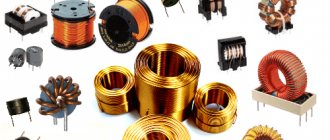
Inductors
It is important to know that resonant circuits do not increase the amount of electrical energy in the circuits. They can only increase voltages, sometimes to dangerous levels. Direct current does not cause resonance phenomena.
Along with the beneficial properties of resonance phenomena, in practical electrical engineering situations often arise when voltage resonance is harmful. This is mainly due to an undesirable increase in current parameters in sections of the circuits. An example is dangerous resonance phenomena in cable lines without load, which can lead to insulation breakdowns. To prevent this from happening, ballast load elements are installed at the end sections of such lines.
Using voltage resonance to transmit a radio signal
This type of oscillating circuit is created from a series combination of three basic components: resistor, capacitor, inductance. A suitable condition for resonance is zero circuit resistance (complex). To solve such a problem, you should study the basic formulas.
Complex resistance Rк=R+j(wL-1/wC). A fixed resistor (R) does not depend on frequency (w). This means that you will have to operate with inductive and capacitive elements. The resonance effect is obtained at (wL-1/wC)=0. To calculate the required values, use the following calculations:
- Lп=1/w2*C;
- Sp=1/w2*L;
- Wп=1/√L*C.
From the given data it is clear that you can adjust any of the parameters while maintaining the other two. In practical circuit design, it is more convenient to work with frequency, so we will consider in more detail the use of this option.
Sequential circuit with graphs
The figures show the conditions for the occurrence of voltage resonance. At the point designated w0, equality of the inductive and capacitive components at a certain frequency is observed. The slight shift to the left along the axis is due to the resistive component of the circuit.
The voltage on the capacitor (Uc) at the resonance frequency (W0) is equal to the characteristic impedance of the oscillatory circuit (p=√L/C). A similar potential difference will occur at the coil terminals at frequency W0. This feature explains the special name of the process – “stress resonance”. The following definitions are also used in electrical calculations:
- Quality factor – Q=p/R;
- Attenuation – 1/Q.
The noted properties are used in radio receiving and transmitting equipment. Isolating a specific range by the circuit allows you to tune the station to a specific frequency with an error determined by the circuit parameters. To control selectivity, the signal amplitude is estimated relative to the resonant frequency. The level of deviation of 3 dB in both directions (0.7 from the maximum) is called the passband.
Amplitude-frequency response (AFC) and bandwidth
Series oscillating circuit
In an oscillatory circuit you can obtain undamped oscillations if you connect it to an alternating current source. If the source is connected in series with a coil L and a capacitor C, then such a circuit is called a series oscillatory circuit (Fig. 3).
When an external source is connected to the circuit, it is not the circuit’s own (free) oscillations that arise, which are determined by the values of L and C, but with the frequency of the source voltage U=Um∙sinω∙t. Such circuit oscillations are called forced. During forced oscillations, the circuit elements L, C will have, depending on the source frequency, certain inductive XL and capacitive Xc resistances and corresponding voltage drops UL, Uc across them. But the circuit has not only reactance, but also an active loss resistance R, which is basically equal to the resistance of the coil wire.
Since the voltages in the coil and capacitor are shifted relative to the current by different phase angles, they can be shown more clearly in vector diagrams (Fig. 4)
It will be interesting➡ SPD - surge protection device
The voltage across the inductive reactance UL leads the current by 90°, and the voltage across the capacitive reactance Uc lags the current at the same angle of 90°. And it turns out that the vectors UL and Uc are shifted by 180°, i.e. are in antiphase. The voltage vector at the source U will be equal to the geometric sum of the voltage of the vector UR and the vector of the voltage difference of the reactances UL-Uc.
As can be seen from the diagram in Fig. 4a, at UL > Uc, the external source voltage leads the current in the oscillatory circuit by an angle φ<90° and is located above the abscissa axis in the inductance voltage zone. This means that in this case the circuit has an inductive resistance. At UL < Uc (Fig. 4b), the source vector will already lag behind the current vector by an angle φ<90° and the circuit will have capacitive reactance.
The total resistance of the circuit Z will be equal to:
The amplitude value of the current Im is determined by the formula:
where Um is the amplitude voltage of the source, and ω is its angular frequency.
When equality is satisfied:
Physical definition and binding to objects
Resonance, by definition, can be understood as a fairly simple process:
- there is a body that is at rest or oscillates with a certain frequency and amplitude;
- it is acted upon by an external force with its own frequency;
- in the case when the frequency of the external influence coincides with the natural frequency of the body in question, a gradual or sharp increase in the amplitude of oscillations occurs.
However, in practice the phenomenon is considered as a much more complex system. In particular, the body can be represented not as a single object, but as a complex structure. Resonance occurs when the frequency of the external force coincides with the so-called total effective oscillatory frequency of the system.
Resonance, if we consider it from the standpoint of physical definition, must certainly lead to the destruction of the object. However, in practice there is a concept of the quality factor of an oscillatory system. Depending on its value, resonance can lead to various effects:
- with a low quality factor, the system is not able to retain oscillations coming from outside to a large extent. Therefore, there is a gradual increase in the amplitude of natural vibrations to a level where the resistance of materials or connections does not lead to a stable state;
- high quality factor, close to unity, is the most dangerous environment in which resonance often leads to irreversible consequences. These may include both mechanical destruction of objects and the release of large amounts of heat at levels that can lead to fire.
Also, resonance occurs not only under the action of an external force of an oscillatory nature. The degree and nature of the system's response is, to a large extent, responsible for the consequences of externally directed forces. Therefore, resonance can occur in a variety of cases.
Parallel oscillatory circuit
In a parallel oscillating circuit, the signal source is connected to an inductor and a capacitor in parallel (Fig. 11). When an alternating voltage is applied to the circuit, energy is exchanged between the capacitor and the coil, but only in the circuit inside the circuit.
For resonance to occur in it, as in a series circuit, the necessary conditions are the equality of the capacitive Xc and inductive XL resistances, as well as the equality of the natural oscillation frequency of the circuit and the oscillation frequency of the current source. Only resonance in a parallel oscillatory circuit, in contrast to resonance in a series circuit, is called current resonance.
In an ideal parallel circuit (without losses), the vectors of inductive Ic and capacitive current IL (at XL=Xc) at resonance will be directed in opposite directions and the total current will go to zero (Fig. 14a). This means that the circuit resistance will tend to infinity. But in a real parallel circuit there is a loss resistance R which is concentrated mainly in the inductance (Figure 14b) and therefore, even at resonance, the current in the circuit is no longer zero, but is equal to the active component of the current in the coil circuit - Iк=IL+IR. This means that the total resistance of the circuit Z will no longer be infinite, but equal to:
Z=L/CR.
Figure 15 shows a graph of the characteristics of the dependence of the current Ik and the impedance Z of the parallel circuit on frequency.
We can conclude: there are two currents in the parallel circuit circuit - the current from the source I flowing through the active loss resistance of the coil and the reactive circuit current Ik. A reactive current of quite large magnitude flows inside the circuit:
Iк=IQ,
but it consumes a small current from the source, which is only necessary to compensate for losses in the circuit:
I=U/Z.
The quality factor Q of a parallel circuit, in contrast to a series circuit, shows how many times the current in the circuit elements is greater than the source current consumption:
Q ≈ Iк/I.
Figure 16 gives a specific example of a parallel oscillating circuit, where it is clear that the circuit current is Q times greater than the source current.
Radio receivers also use direct connection of the oscillating circuit with the antenna, i.e. the circuit is connected in parallel to the signal source (Fig. 17). Using a variable capacitor, we tune the circuit to the signal frequency of the desired radio station. At resonance, the loop current caused by the desired radio station becomes relatively large, and the loop resistance is also large. Therefore, a significant voltage is obtained between points a and b. For other stations, the circuit represents low resistance and the radio station signal goes to ground.
The benefits and harms of resonance
In order to draw some conclusion about the pros and cons of resonance, it is necessary to consider in which cases it can manifest itself most actively and noticeably for human activity.
Positive effect
The response phenomenon is widely used in science and technology. For example, the operation of many radio circuits and devices is based on this phenomenon.
- Two-stroke engine. The muffler of a two-stroke engine has a special shape designed to create a resonant phenomenon. It improves engine performance by reducing consumption and pollution. This resonance partially reduces the unburned gases and increases compression in the cylinder.
- Musical instruments. In the case of string and wind instruments, sound production occurs mainly when the oscillatory system (strings, columns of air) is excited until the phenomenon of resonance occurs.
- Radios. Each radio station emits an electromagnetic wave with a clearly defined frequency. To capture it, the RLC circuit is forcibly vibrated by an antenna, which captures all electromagnetic waves that reach it. To listen to one station, the natural frequency of the RLC circuit must be tuned to the frequency of the desired transmitter by changing the capacitance of the variable capacitor (the operation is performed by pressing the station search button). All radio communication systems, whether transmitters or receivers, use resonators to "filter" the frequencies of the signals they process.
- Magnetic resonance imaging (MRI). In 1946, two Americans, Felix Bloch and Edward Mills Purcell, independently discovered the phenomenon of nuclear magnetic resonance, also called NMR, which earned them the Nobel Prize in Physics.
Negative impact
However, the phenomenon is not always useful. You can often find references to cases where suspension bridges broke when soldiers walked across them “in step.” At the same time, they refer to the manifestation of the resonant effect of resonance, and the fight against it becomes large-scale.
- Motor transport. Motorists are often annoyed by noise that occurs at certain vehicle speeds or as a result of engine operation. Some slightly rounded parts of the body resonate and emit sound vibrations. The car itself, with its suspension system, is an oscillator, equipped with effective shock absorbers that prevent sharp resonance from occurring.
- Bridges. The bridge can perform vertical and transverse vibrations. Each of these types of oscillations has its own period. If the lines are suspended, the system has a very different resonant frequency.
- Building. Tall buildings are susceptible to earthquakes. Some passive devices help protect them: they are oscillators whose natural frequency is close to the frequency of the building itself. Thus, the energy is completely absorbed by the pendulum, preventing the destruction of the building.
Next
MiscellaneousHow to check voltage with a multimeter?
Types and examples of resonance
Only in physics itself do we distinguish such types of resonance as:
- Mechanical resonance is the same aforementioned swing, the resonance of a bridge from a passing company of soldiers, the resonance of a bell ringing, etc. In a word, resonance caused by mechanical influences.
- Acoustic resonance is the resonance that makes all stringed musical instruments work: guitar, violin, lute, balalaika, banjo, etc. By the way, the body of musical instruments has its own shape for a reason. The sound produced by the string when plucked enters the body and there enters into resonance with the walls, which as a result leads to its amplification. For this reason, the sound quality of the same guitar greatly depends on the material from which it is made and even on the varnish with which it is coated.
- Electrical resonance is the coincidence of the oscillation frequency of the external voltage with the oscillation frequency of the electrical circuit through which the current flows.
In addition to these purely physical resonances, there is also the public resonance that we have already mentioned - a strong public response to some event (usually political or economic), for example, Brexit, Britain, its withdrawal from the European Union caused a wide public resonance in many European countries and especially, of course, in Britain itself.
There is also cognitive resonance - this is a complete coincidence in views and opinions. For example, you met a new person, and he thinks the same way as you, you have absolutely similar views, tastes, preferences, then cognitive resonance takes place. And the opposite phenomenon is cognitive dissonance, when you absolutely disagree with someone or something and absolutely do not accept what is happening. (For example, the author of this article, finding himself in some Ukrainian bureaucratic institution, be it Zheka, BTI or tax office, experiences real cognitive dissonance)).