In general physical concepts, resonance conditions arise when the frequency of external influences coincides with the internal parameters of the system. A good example is the swing of a pendulum. With the correct selection of movements, weak force significantly increases the amplitude of oscillations. A similar result can be obtained in electrical circuits that are composed of components with reactive characteristics.
Definition of resonance
Using voltage resonance to transmit a radio signal
This type of oscillating circuit is created from a series combination of three basic components: resistor, capacitor, inductance. A suitable condition for resonance is zero circuit resistance (complex). To solve such a problem, you should study the basic formulas.
Complex resistance Rк=R+j(wL-1/wC). A fixed resistor (R) does not depend on frequency (w). This means that you will have to operate with inductive and capacitive elements. The resonance effect is obtained at (wL-1/wC)=0. To calculate the required values, use the following calculations:
- Lп=1/w2*C;
- Sp=1/w2*L;
- Wп=1/√L*C.
From the given data it is clear that you can adjust any of the parameters while maintaining the other two. In practical circuit design, it is more convenient to work with frequency, so we will consider in more detail the use of this option.
Sequential circuit with graphs
The figures show the conditions for the occurrence of voltage resonance. At the point designated w0, equality of the inductive and capacitive components at a certain frequency is observed. The slight shift to the left along the axis is due to the resistive component of the circuit.
The voltage on the capacitor (Uc) at the resonance frequency (W0) is equal to the characteristic impedance of the oscillatory circuit (p=√L/C). A similar potential difference will occur at the coil terminals at frequency W0. This feature explains the special name of the process – “stress resonance”. The following definitions are also used in electrical calculations:
- Quality factor – Q=p/R;
- Attenuation – 1/Q.
The noted properties are used in radio receiving and transmitting equipment. Isolating a specific range by the circuit allows you to tune the station to a specific frequency with an error determined by the circuit parameters. To control selectivity, the signal amplitude is estimated relative to the resonant frequency. The level of deviation of 3 dB in both directions (0.7 from the maximum) is called the passband.
Amplitude-frequency response (AFC) and bandwidth
Application in practice
Let's consider the benefits and harms of resonance of currents and voltages. The resonance phenomenon has brought the greatest benefit to radio transmitting equipment. In simple words, the receiver circuit has a coil and a capacitor connected to the antenna. By changing the inductance (for example, by moving the core) or the capacitance value (for example, with an air variable capacitor), you tune the resonant frequency. As a result, the voltage on the coil increases and the receiver catches a certain radio wave.
These phenomena can cause harm in electrical engineering, for example, on cable lines. The cable represents inductance and capacitance distributed along its length if voltage is applied to the long line in no-load mode (when there is no load connected at the end of the cable opposite the power source). Therefore, there is a danger that an insulation breakdown will occur; to avoid this, a load ballast is connected. Also, a similar situation can lead to failure of electronic components, measuring instruments and other electrical equipment - these are dangerous consequences of this phenomenon.
Natural frequency of the resonant circuit
Resistor power
The capacitance of the capacitor (C) together with the inductance of the coil (L) determines the natural frequency of the circuit (Wc). For approximate calculations, use the formula Wc=1/√L*C. In this case, we are talking about ideal conditions when losses are neglected due to minimal values.
To increase accuracy, the attenuation coefficient (Kz) is used. Taking this factor into account, the following relationship between natural and resonant frequencies can be given:
Wo=√Wc2-2*Кз2.
What types of resonance exist?
The phenomenon is characterized by features; types are distinguished:
- Mechanical. When designing industrial facilities, safety measures must be taken into account. If the mechanical frequencies of the basis of machines and mechanisms coincide with the vibrations of the engine, a resonant effect may occur.
- Electric. Observed in electrical circuits at a certain frequency. The phenomenon is used in wireless signal transmission - television, cellular communications.
- Optic. With a special arrangement of optical cavities (mirrors), a resonator for light waves is observed. The phenomenon is used in laser systems and parametric generators.
- Nuclear magnetic resonance. Abbreviated as NMR, it is used in medical diagnostics, when performing magnetic resonance imaging.
- Public. Society often uses the concept of a response to an event, phenomenon or random occurrence. The response to the incident is a similar reaction of a large mass of people. A recent example is the increase in the retirement age introduced by Federal Law in 2022. As a result, the response from the majority of citizens was the same - negative and disagreement with the decision.
- Cognitive or psychological. If the subject meets someone and has a positive impression, we can talk about the consequence of resonance. At the same time, interests, judgments, and opinions coincide. In psychology, resonance is the unity of souls, aspirations and emotions.
- Plasmon resonance. In quantum physics, the concept of plasmon is used. These are quasiparticles in current conductors, when excited at a certain frequency that coincides with an external electromagnetic wave. The phenomenon is used in the design of sensors for chemical or biological systems.
The phenomenon of resonance is a very effective way to implement many tasks in everyday life, science, music, and construction. It must be remembered that there is a negative impact, it must be prevented as much as possible in order to prevent destruction and health problems.
Current resonance, parallel resonance
In electrical engineering, a parallel rather than series connection of a capacitor and a coil is often used.
Something to remember! In such a situation, the reactive elements are considered according to a modified circuit. Instead of resistances, they operate with the sum of conductivities.
Electrical parameters and components, vector diagrams of voltages and currents
In this example, we will consider the refined parameters. The value (I) is determined by the sum of the currents that pass through the inductive and capacitive sections of the circuit. In both situations, the frequency ( w ) has a certain meaning:
- IL=E/(RL+Кз*w*L);
- Ic=E/(Rc+(1/Кз*w*С).
The diagrams clearly demonstrate characteristic changes in physical parameters when the circuit operates in three typical modes. Figure a) shows the capacitive version. It is assumed that w*L is greater than 1/w*С. In this case, the minimum value of RL can be neglected, which somewhat simplifies the above formula for calculating the current. It will lag behind the voltage vector by an angle ϕL. The second figure shows the opposite situation, when IL is greater than Ic.
For resonant conditions, the phases must coincide. This is shown by the vectors in Figure c). This situation will happen if w*L is equal to 1/ w*C. In this case, there is an approximate equality of IL and Ic, which is defined in the second name of the phenomenon - “current resonance”.
Description of the phenomenon
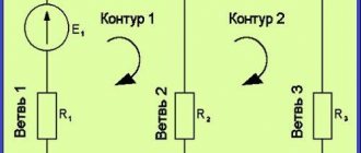
If in a certain electrical circuit (see Fig. 1) there are capacitive and inductive elements that have their own resonant frequencies, then when these frequencies coincide, the amplitude of the oscillations will increase sharply. That is, there is a sharp surge in stress on these elements. This can cause destruction of electrical circuit elements.
Rice. 1. Resonance in an electrical circuit
Let's look at this example to see what phenomena will occur when an alternating current generator is connected to the contacts of the circuit. Note that coils and capacitors have properties that can be compared to the analogue of a reactive resistor. In particular, a choke in an electrical circuit creates inductive reactance. The capacitor causes capacitance.
The inductive element causes a phase shift, characterized by a lag of the current from the voltage by ¼ of a period. Under the action of a capacitor, the current, on the contrary, leads the voltage by ¼ period.
In other words, the effect of inductance is opposite to the effect on the phase shift of capacitance. That is, inductors and capacitive elements influence the generator in different ways and adjust the phase relationships between electric current and voltage in their own way.
The total reactance of the elements we are considering is equal to the sum of the resistances of each of them. Taking into account the opposite actions, we can write: Xtot = XL - Xc, where XL = ωL is the inductive reactance, the expression Xc = 1/ωC is the capacitive reactance.
Figure 2 shows graphs of the dependence of the circuit impedance and the associated current on the reactance of the inductive element. Pay attention to how the total resistance decreases as the reactance RL decreases (graph b) and how the current increases (graph c).
Rice. 2. Graphs of the dependence of current parameters on the drop in reactance
Electrical circuits consisting of series-connected capacitors, passive resistors and inductors are called series resonant (oscillatory) circuits (see Fig. 2). There are also parallel circuits in which R, L, C elements are connected in parallel (Fig. 3).
Rice. 3. Series oscillatory circuit
Rice. 4. Parallel oscillatory circuit
In resonance mode, the power of the power source will be dissipated only through active resistances (including the active resistance of the coil). Resonant circuits are characterized by losses only of active power, which is spent to maintain the oscillatory process. Reactive power on LC elements is not consumed. The current in the resonant mode takes on the maximum value:
The value of Q is usually called the term “Q factor” of the circuit. This parameter shows how many times the voltage generated at the contacts of the reactive elements exceeds the input voltage U of the electrical network. To describe the ratio of output and input voltages, the coefficient K is often used. At resonance:
K = Uout / Uin = UC0 / U = Q
Based on the phenomena described above, we formulate the definition of resonant voltage: “If the total voltage drop across the capacitive-inductive elements is zero and the current amplitude is maximum, then this special state of the system is called voltage resonance.” For a better understanding of the phenomenon, let us rephrase the definition a little: voltage resonance is a state when the voltage on the CL circuit is greater than at the input of the electrical circuit.
The described phenomenon is quite common in electrical engineering. Sometimes they fight it, and sometimes they specially create conditions for the formation of resonance. The main characteristics of any resonant circuit are the quality factor and frequency parameters [1].
If XL = Xc, the equality is true: ωL = 1/ωC, from here we obtain:
If ω = ω0 – voltage resonance occurs. The frequencies coincide when the inductive reactance is equal to the capacitive reactance of the capacitor. In such cases, only active resistance R will act in the circuit. The presence of reactive elements in the circuit leads to an increase in the total resistance of the circuit (Z):
where R is the total active resistance.
Considering that, according to Ohm's law, U = I/Z, it can be argued that the total voltage in the circuit depends, among other things, on the terms of the inductive and capacitive reactance.
If in the circuit under consideration (Fig. 1) there was no active resistance R, then the value of the total resistance Z would tend to 0. Consequently, the voltage on the reactive elements increases to a critical level.
It will be interesting➡ What is automatic reserve entry and how does ATS work? Basic ATS schemes and their features.
Since XL and Xc depend on the frequency of the input voltage, for resonance to occur, you must select the appropriate network frequency, or change the parameters of the coil or capacitor until the resonant frequencies coincide. Any violation of the resonance conditions immediately leads to the system exiting the resonant mode with a subsequent voltage drop.
Resonance phenomena occur only if the following conditions are present:
- The presence of minimal active resistance in a section of the electrical circuit.
- Equality of reactances arising on the LC chain.
- Coincidence of the input frequency of the power supply with the resonant frequency of the oscillatory circuit.
When there is resonance in the circuit, the voltages on its elements can increase by an order of magnitude or more.
Resonance in distributed oscillatory systems, nonlinear processes
A common concept for all phenomena in this category can be called an effective connection with the environment. In mechanical systems, the amplitude of the phase characteristics of the process is influenced by a certain position in space. In the oscillatory circuit of a radio receiver, in addition to its own attenuation, it is necessary to take into account the real electromagnetic background. Under certain conditions with a high quality factor, the formation of standing waves is permissible.
You should understand! The result of the impact largely depends on the coincidence in phase and frequency.
If the spring is created with a different coil density distribution, the standard formulas do not apply. Standard calculations assume uniform elasticity and deformation of each part. To clarify nonlinearity, correction factors and complex multi-stage calculation schemes are used.
Similar features are taken into account when using diodes or other radio components with variable amplitude-frequency characteristics. If the inductor is wound on a core made of ferromagnetic material, the nonlinearity of the output parameters will also have to be taken into account. It cannot be described by the elementary equation of Ohm's law.
In nonlinear circuits with a certain spectral distribution of external influences, harmonic oscillations are present. In addition to the coincidence of frequencies, their amplitude is important. Depending on the settings, they are capable of performing useful and harmful functions. Certain conditions cause the underlying waveform to become distorted.
The benefits and harms of resonance
In order to draw some conclusion about the pros and cons of resonance, it is necessary to consider in which cases it can manifest itself most actively and noticeably for human activity.
Positive effect
The response phenomenon is widely used in science and technology. For example, the operation of many radio circuits and devices is based on this phenomenon.
- Two-stroke engine. The muffler of a two-stroke engine has a special shape designed to create a resonant phenomenon. It improves engine performance by reducing consumption and pollution. This resonance partially reduces the unburned gases and increases compression in the cylinder.
- Musical instruments. In the case of string and wind instruments, sound production occurs mainly when the oscillatory system (strings, columns of air) is excited until the phenomenon of resonance occurs.
- Radios. Each radio station emits an electromagnetic wave with a clearly defined frequency. To capture it, the RLC circuit is forcibly vibrated by an antenna, which captures all electromagnetic waves that reach it. To listen to one station, the natural frequency of the RLC circuit must be tuned to the frequency of the desired transmitter by changing the capacitance of the variable capacitor (the operation is performed by pressing the station search button). All radio communication systems, whether transmitters or receivers, use resonators to "filter" the frequencies of the signals they process.
- Magnetic resonance imaging (MRI). In 1946, two Americans, Felix Bloch and Edward Mills Purcell, independently discovered the phenomenon of nuclear magnetic resonance, also called NMR, which earned them the Nobel Prize in Physics.
Negative impact
However, the phenomenon is not always useful. You can often find references to cases where suspension bridges broke when soldiers walked across them “in step.” At the same time, they refer to the manifestation of the resonant effect of resonance, and the fight against it becomes large-scale.
- Motor transport. Motorists are often annoyed by noise that occurs at certain vehicle speeds or as a result of engine operation. Some slightly rounded parts of the body resonate and emit sound vibrations. The car itself, with its suspension system, is an oscillator, equipped with effective shock absorbers that prevent sharp resonance from occurring.
- Bridges. The bridge can perform vertical and transverse vibrations. Each of these types of oscillations has its own period. If the lines are suspended, the system has a very different resonant frequency.
- Building. Tall buildings are susceptible to earthquakes. Some passive devices help protect them: they are oscillators whose natural frequency is close to the frequency of the building itself. Thus, the energy is completely absorbed by the pendulum, preventing the destruction of the building.
Next
MiscellaneousWhat is voltage?
Resonance in linear systems with one degree of freedom
The considered serial and parallel electrical circuits can be included in this group. A mechanical example is a spring with a load that can only move in a vertical straight line. Gusts of wind, vibrations, and other “parasitic” external influences are excluded. In such conditions, standard formulas for linear systems can be used.
The quality factor noted above is the determining factor for frequency selectivity. Narrowing the width of the resonant range helps improve the performance of receiving and transmitting devices. In addition to economical consumption of electricity, with proper design of the circuit, noise immunity is significantly improved.
Physical definition and binding to objects
It is easy to study mechanical resonance; what it is is explained in simple words as follows. If a large bell is struck too often, the sound quickly fades. By gradually increasing the interval, even without changing the force of impact, powerful sound vibrations can be created. This example demonstrates the coincidence of the frequencies indicated above.
When reducing the size of the bell, to obtain the desired effect, change the rhythm of the influences
In complex systems, it is necessary to take into account the presence of several resonant frequencies and the corresponding total indicator. Also worth noting is the quality factor. This term usually means the ability of an object to perceive external vibrations. At values close to unity, a critical increase in the oscillation amplitude is permissible, up to mechanical destruction.
Parallel resonance with an EMF source
The quality factor for a parallel circuit is calculated using the formula Q=R√C/L. If the frequencies (source and circuit) are equal, the resistance in the individual branches does not differ. Identical current values are created by compensated reactive parameters of the capacitor and coil.
When the frequency deviates from the resonant value to the lower (upper) range, the resistance acquires a capacitive (inductive) character, respectively. In a normal operating cycle, energy exchange occurs between the reactive elements of the circuit. This mode is characterized by a Q times increase in the current passing through the internal circuit compared to that coming from the EMF source. Ideal conditions, when the quality factor tends to an infinite value, are impossible. Direct and parasitic losses in circuits limit the growth of the resonant current strength.
Parallel oscillatory circuit
In a parallel oscillating circuit, the signal source is connected to an inductor and a capacitor in parallel (Fig. 11). When an alternating voltage is applied to the circuit, energy is exchanged between the capacitor and the coil, but only in the circuit inside the circuit.
For resonance to occur in it, as in a series circuit, the necessary conditions are the equality of the capacitive Xc and inductive XL resistances, as well as the equality of the natural oscillation frequency of the circuit and the oscillation frequency of the current source. Only resonance in a parallel oscillatory circuit, in contrast to resonance in a series circuit, is called current resonance.
In an ideal parallel circuit (without losses), the vectors of inductive Ic and capacitive current IL (at XL=Xc) at resonance will be directed in opposite directions and the total current will go to zero (Fig. 14a). This means that the circuit resistance will tend to infinity. But in a real parallel circuit there is a loss resistance R which is concentrated mainly in the inductance (Figure 14b) and therefore, even at resonance, the current in the circuit is no longer zero, but is equal to the active component of the current in the coil circuit - Iк=IL+IR. This means that the total resistance of the circuit Z will no longer be infinite, but equal to:
Z=L/CR.
Figure 15 shows a graph of the characteristics of the dependence of the current Ik and the impedance Z of the parallel circuit on frequency.
We can conclude: there are two currents in the parallel circuit circuit - the current from the source I flowing through the active loss resistance of the coil and the reactive circuit current Ik. A reactive current of quite large magnitude flows inside the circuit:
Iк=IQ,
but it consumes a small current from the source, which is only necessary to compensate for losses in the circuit:
I=U/Z.
The quality factor Q of a parallel circuit, in contrast to a series circuit, shows how many times the current in the circuit elements is greater than the source current consumption:
Q ≈ Iк/I.
Figure 16 gives a specific example of a parallel oscillating circuit, where it is clear that the circuit current is Q times greater than the source current.
Radio receivers also use direct connection of the oscillating circuit with the antenna, i.e. the circuit is connected in parallel to the signal source (Fig. 17). Using a variable capacitor, we tune the circuit to the signal frequency of the desired radio station. At resonance, the loop current caused by the desired radio station becomes relatively large, and the loop resistance is also large. Therefore, a significant voltage is obtained between points a and b. For other stations, the circuit represents low resistance and the radio station signal goes to ground.
Series resonance with current source
Measuring resistance in a circuit with reactive elements connected in series will help detect resonance at a certain frequency. In this case, a current source is used for the experiment. At low (high) frequencies, the capacitive (inductive) characteristics of the circuit have a limiting effect. At the resonance frequency, the total reactance is minimal.
Electrical parameters in series circuit
The figures show the following dependences on frequency:
- A. general resistance;
- b. reactive components;
- V. current strength in resonant modes.
Series oscillating circuit
In an oscillatory circuit you can obtain undamped oscillations if you connect it to an alternating current source. If the source is connected in series with a coil L and a capacitor C, then such a circuit is called a series oscillatory circuit (Fig. 3).
When an external source is connected to the circuit, it is not the circuit’s own (free) oscillations that arise, which are determined by the values of L and C, but with the frequency of the source voltage U=Um∙sinω∙t. Such circuit oscillations are called forced. During forced oscillations, the circuit elements L, C will have, depending on the source frequency, certain inductive XL and capacitive Xc resistances and corresponding voltage drops UL, Uc across them. But the circuit has not only reactance, but also an active loss resistance R, which is basically equal to the resistance of the coil wire.
Since the voltages in the coil and capacitor are shifted relative to the current by different phase angles, they can be shown more clearly in vector diagrams (Fig. 4)
It will be interesting➡ Who invented electricity? The history of the development of electricity - who discovered it and in what year
The voltage across the inductive reactance UL leads the current by 90°, and the voltage across the capacitive reactance Uc lags the current at the same angle of 90°. And it turns out that the vectors UL and Uc are shifted by 180°, i.e. are in antiphase. The voltage vector at the source U will be equal to the geometric sum of the voltage of the vector UR and the vector of the voltage difference of the reactances UL-Uc.
As can be seen from the diagram in Fig. 4a, at UL > Uc, the external source voltage leads the current in the oscillatory circuit by an angle φ<90° and is located above the abscissa axis in the inductance voltage zone. This means that in this case the circuit has an inductive resistance. At UL < Uc (Fig. 4b), the source vector will already lag behind the current vector by an angle φ<90° and the circuit will have capacitive reactance.
The total resistance of the circuit Z will be equal to:
The amplitude value of the current Im is determined by the formula:
where Um is the amplitude voltage of the source, and ω is its angular frequency.
When equality is satisfied:
Resonance in real circuits
To study the described processes, it is necessary to assemble a circuit from the appropriate components. You will have to prepare a generator with a variable output signal frequency, an oscilloscope and other measuring instruments. To get reliable results without unnecessary difficulties, use specialized software.
Theory and practice
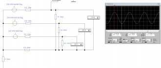
The left side of the figure shows the circuit and amplitude of the output signal when connected to the terminals of a parallel circuit capacitor. On the right is a screenshot of the measuring equipment. It is easy to verify the identity of the vibrations.
For your information. Using the software, dozens of experiments can be performed quickly and accurately in normal home conditions. This method greatly simplifies the creation of electrical circuits with optimal parameters.
Inductance and capacitance reactances
Inductance is the ability of a body to accumulate energy in a magnetic field. It is characterized by a phase lag between the current and the voltage. Typical inductive elements are chokes, coils, transformers, electric motors.
Capacitance refers to elements that accumulate energy using an electric field. Capacitive elements are characterized by a phase lag between voltage and current. Capacitive elements: capacitors, varicaps.
Their main properties are given; the nuances are not taken into account within the scope of this article.
In addition to the listed elements, others also have a certain inductance and capacitance, for example in electrical cables distributed along its length.
Resonance in linear oscillatory systems with several degrees of freedom
Such calculations will be needed when designing two series circuits with inductive coupling. In this case, the alternating oscillatory processes exert mutual influence. In fact, we are talking about a distributed system.
In addition to circuit design, in such situations the coupling coefficient (Kc) is studied separately. When working with a transformer, it is calculated by dividing the voltages on the primary (secondary) coil, respectively. It is necessary to take into account the reactive characteristics that prevail in the operating frequency range.
Having learned what resonance of voltages and currents is, you can independently implement various projects. Careful preliminary preparation is necessary to create a circuit with good performance parameters. They start with drawings and calculations. Theoretical research is complemented by the production of a prototype and practical tests. They speed up the preparation of design documentation and also carry out experiments using software. In the most difficult situations, they turn to experienced specialists.
Quartz resonators and electromechanical filters
These are the most common resonators that include quartz crystals. The crystal is cut in the shape of a parallelepiped. Electrodes are sprayed onto the resulting plate in a vacuum. The modes of vibration of such an element depend on the following positions:
- type of quartz plate;
- design of electrodes;
- method of connecting electrodes.
The value of the natural frequency of a quartz resonator is influenced by: the shape, dimensions, elastic modulus and density of the piezoelectric element, as well as the features of fastening the part.
The simplest design of a quartz resonator
Electromechanical filters (EMFs) perform stepwise conversion. At the first stage, electrical pulsations are converted into vibrations of a mechanical nature. The second stage filters them, the third returns them to electrical form again.
Attention! The second stage is a mechanical resonator, it works like a filter. Made from ferrites with magnetostrictive properties, quartz, iron-nickel alloys, piezoceramic elements and other components
Block diagram of EMF
Application of current resonance
The main area of active application of widely demanded resonant currents today is represented by:
- some types of filter systems in which current with certain frequency parameters has significant resistance values;
- radio equipment in the form of receivers that highlight signals intended for specific points of radio stations. Providing significant resistance to current is accompanied by a decrease in loop voltage at maximum frequency;
- asynchronous motors, especially those operating under part-load conditions;
- high-precision electric welding installations;
- oscillatory circuits inside electronic generator units;
- devices characterized by high-frequency hardening;
- reduction in generator load indicators. Under such conditions, an oscillatory circuit is made in the receiving transformer with the primary winding.
Circuit diagram
Especially often, oscillatory circuits or current resonances are used in the production of modern industrial induction boiler equipment, which makes it possible to significantly improve the starting efficiency indicators.
Standard oscillatory circuits operating under current resonance conditions are widely used as one of the most important components in modern electronic generators.
Typical examples
A textbook and very striking example of resonance is the case of the destruction of the structure of a bridge when a company of soldiers passed along it in formation. The reason for this effect was the coincidence of the step frequency of a group of people and the natural vibration frequency of the structure, which led to a sharp increase in the vibration amplitude of the bridge.
The term “Tacoma Bridge” is also associated with the destruction of bridge structures. But in this case, the cause of the accident was not the company of soldiers, but gusts of wind. When making calculations, the designers did not take into account the possibility of resonance, which included the bridge deck with gusts of wind of a certain speed. After the incident, specialists conducted numerous studies and calculations, which later became the foundation of modern bridge construction.
Another example of the manifestation of resonance, which is already encountered in everyday life, is the operating principle of a microwave oven. As a result of the generation of microwave radiation with a frequency of 2.45 GHz, a sharp increase in the amplitude of vibrations is observed in water molecules entering the impact zone, which leads to an increase in temperature. Thus, due to the coincidence of the frequency of the external influence and the own frequency of the water molecules, the products are heated inside the microwave oven.
Operating principle
This phenomenon is observed
, when a system is capable of storing and easily transferring energy between two or more different storage modes, such as kinetic and potential energy. However, there is some loss from cycle to cycle, called attenuation. When the damping is negligible, the resonant frequency is approximately equal to the natural frequency of the system, which is the frequency of unforced oscillation.
These phenomena occur with all types of oscillations or waves: mechanical, acoustic, electromagnetic, nuclear magnetic (NMR), electron spin (ESR), and quantum wave function resonance. Such systems can be used to generate vibrations of a certain frequency (for example, musical instruments).
The term "resonance" (from the Latin resonantia, "echo") comes from the field of acoustics, especially seen in musical instruments, such as when strings begin to vibrate and produce sound without direct input from the player.
Pushing a man on a swing
is a common example of this phenomenon. A loaded swing, a pendulum, has a natural vibration frequency and a resonant frequency that resists being pushed faster or slower.
An example is the oscillation of projectiles on a playground, which acts like a pendulum. A person's push while swinging at a natural swing interval causes the swing to go higher and higher (maximum amplitude), while attempting to swing at a faster or slower pace creates smaller arcs. This is because the energy absorbed by vibrations increases when the shocks correspond to natural vibrations.
The response occurs widely in nature
and is used in many artificial devices. This is the mechanism by which virtually all sine waves and vibrations are generated. Many of the sounds we hear, such as when hard objects made of metal, glass or wood hit, are caused by short vibrations in the object. Light and other short-wave electromagnetic radiation is created by resonance on the atomic scale, such as electrons in atoms. Other conditions in which the beneficial properties of this phenomenon may apply:
- Timekeeping mechanisms of modern watches, a balance wheel in a mechanical watch and a quartz crystal in a watch.
- Tidal response of the Bay of Fundy.
- Acoustic resonances of musical instruments and the human vocal tract.
- Destruction of a crystal glass under the influence of a musical right tone.
- Frictional idiophones, such as making a glass object (glass, bottle, vase), vibrate when rubbed around its edge with a fingertip.
- The electrical response of tuned circuits in radios and televisions that allow selective reception of radio frequencies.
- Creation of coherent light by optical resonance in a laser cavity.
- Orbital response, exemplified by some of the gas giant moons of the Solar System.
Material resonances on the atomic scale
are the basis of several spectroscopic methods that are used in condensed matter physics, for example:
- Electronic spin.
- Mossbauer effect.
- Nuclear magnetic.