Calculation of electrical loads of a transformer substation
In the technical conditions of power supply, the need to control an existing transformer substations for additional load is increasingly encountered.
How can this be done? Now I will tell you everything and present my simple program, which will take on part of the work. Methodology for calculating loads on the power supply line of a transformer substation.
City substations are used to power residential and public buildings and premises.
The most difficult thing in this calculation is collecting the initial data.
First of all, in electrical networks it is necessary to connect an electrical circuit to the transformer transformer. Unfortunately, this diagram does not indicate the design possibilities, but only the names (addresses) of the associated objects.
If the house is old, finding documentation for this house is not so easy.
Alternatively, you can go to the website and see how many apartments are in a residential building. For each house we have a property passport, which contains information about the number of apartments. It should be taken into account that large houses can be divided into several sections and can be connected by several TPs.
Having collected (calculated) the estimated capacity of each building, you can proceed directly to the calculation.
What is the essence of the calculation?
If we have a two-transformer substation, we need to check the emergency mode for permissible overloads of the emergency transformer, i.e. calculate the load factor of the emergency transformer. If the transformer allows overloads taking into account the additional (design) load, the transformer substation cannot be replaced by transformers.
The design load of a transformer substation can be obtained using the formula:
Р = zd.max + K1 · Рzd1 + K2 · Рzd2 +… + Кн · Рzd.n,
where Rzd.max is the largest electrical load of buildings supplied from the line (transformer substation), kW;
Rzd1,..., Rzd.n - calculated electrical load of each building (1,..., n), with the exception of the building with the highest load Rzd.max, powered from one line (transformer substation), kW;
K1,. Кн - coefficients of mismatch of maximum electrical loads, taking into account the share of electrical loads of public buildings (premises) and residential buildings (apartments and energy consumers) in the highest design load Pzd.max, taken according to table 19 (TKP 45-4.04-149-2009) or table 6.13 (SP 31-110-2003).
To make it clearer, I’ll take a simple example. Let's say we have two residential buildings: a residential building with electric stoves - 100 kW and a residential building with gas stoves - 70 kW.
Pp = 100 + 0.9 * 70 = 163 kW, K1 = 0.9 - selected from the table.
But there is a nuance in this calculation that nothing is said about.
For example, there are 3 houses with gas stoves:
1100 apartments, Rud = 1.13 kW;
2100 apartments, Rud = 1.13 kW;
3200 apartments, Rud = 1.03 kW;
We will simplify the calculation and will not take into account elevators and other small loads.
P (100) = 113 kW, p (200) = 206 kW.
We calculate the load using our calculation method:
I believe that such a calculation gives an overestimated design capacity, and when calculating houses of the same type it is necessary to combine them into one building.
400 apartments - Rud = 0.95, which means Rr = 0.95 * 400 = 380 kW.
Despite the fact that my thoughts differ somewhat from the proposed methodology of regulatory documents, I believe that this would be more correct.
Of course, it is absolutely forbidden to combine apartments with electric and gas stoves.
This is called calculation manipulation.
To speed up the calculation, I made a simple program. The appearance is shown below:
TP load calculation program
Basics of calculation of electrical substations
Initial conditions
Before calculating the transformer substation, you will need to consider the following points:
- The load indicator of station equipment is determined by the power of all electrical consumers connected to the transformer substation and losses in the distribution network.
- The consumption mode of electricity receivers is never constant.
- The load in such lines changes all the time, which causes a change in the power consumed from the transformer transformer.
The nature of load changes must be taken into account when calculating substation equipment (including the parameters of busbars, power transformers and converters). It must be taken into account when calculating the amount of heat loss, the range of changes in the mains voltage, as well as when choosing protection devices and compensating devices.
Load calculation
Before calculating transformer substations, you should know that their power “P” is determined as the sum of the loads on the input busbars of all connected consumers.
Important! This indicator should be calculated taking into account the simultaneity factor.
The latter is introduced as a correction factor for existing networks with a voltage of 380/220 Volts and is indicated in special tables (see below).
Calculating the power of a transformer substation for each section of the line means taking into account all the same type of loads connected simultaneously and with approximately the same energy consumption values. However, in a real situation, these indicators are distributed completely differently, which is reflected in seasonal, annual and daily charts.
A very good confirmation of this is the amount of reactive power (as a component of total consumption), which increases significantly at night. For most private and public facilities, this is due to the fact that gas-discharge street lighting lamps are turned on at night, as well as service lighting in public buildings.
Additional information: This calculation also takes into account peak and unbalanced demand values associated with large inductive loads (such as electric motors).
To power rural settlements and gardening partnerships, where a mixed type of load predominates, one or two 10 / 0.4 kV transformer substations with a power of up to 10 kVA are sufficient. When choosing the type of distribution board for urban areas, preference is given to package transformer substations with a “P” value of up to 160 kVA. The indicated efficiency indicators are fixed mainly by the power of the transformers used in the transformer substations.
Transformer performance optimization
To optimize the operation and reduce the cost of transformer substations, the following technical measures are taken:
- Circuits are used where switches cannot be installed on the higher voltage side.
- Transformers installed in a workshop should not have distribution boards on the overvoltage side.
- When installing a radial power circuit, the power cable is connected directly to the transformer.
- When using a mains power supply, the power cable is connected through a switch or load break switch.
Selection of measuring current transformers - main characteristics
The article describes the main parameters of current transformers.
Transformation ratio
Rated transformation ratio is the ratio between the rated primary winding current and the rated secondary winding current, which is indicated as an irregular fraction on the rating plate.
The most commonly used instrument transformers are x/5A, most instruments have a higher accuracy class of 5A. For technical and especially economic reasons, for long measuring lines it is recommended to use x transformers / 1 A. The line losses in 1 A transformers are only 4% of 5 A transformers. But in this case, the measuring instruments usually have a lower accuracy class.
Rated current
Rated or rated current (previously used name) is the primary and secondary current (primary rated current, secondary rated current) indicated on the nameplate for which the transformer is rated. Rated currents (excluding classes 0.2 S and 0.5 S) are 10 - 12.5 - 15 - 20 - 25 - 30 - 40 - 50 - 60 - 75 A, plus numbers derived from these values multiplied by multiples quite often.
Rated secondary currents are 1 and 5 A, preferably 5 A.
The normalized current ratings for classes 0.2 S and 0.5 S are 25-50-100 A, as are the numbers obtained from these values by multiplying by ten, the secondary current is (only) 5 A.
The correct selection of the primary current rating is very important for measurement accuracy. It is recommended that the ratio closest to the measured/set current (In) be as close to the maximum as possible.
Example: In = 1,154 A; selected ratio = 1,250/5.
The rated current can be determined under the following conditions:
- Instrument transformer current rating multiplied by 1.1 (transformer with closest specification)
- Fuse (fuse rated current = transformer rated current) of the metering part of the installation (low voltage main distribution boards, distribution cabinets)
- Rated effective current multiplied by 1.2 (this method should be used if the effective current is significantly less than the rated current of the transformer or fuse)
It is not recommended to use transformers with overrated values, since in this case the measurement accuracy can be significantly reduced at relatively low currents (compared to the rated primary winding current).
Rated power of current transformers
The current transformer rating is the result of the meter load and the quadrant of the secondary winding current rating and is measured in VA. Standardized values are 2.5 - 5 - 10 - 15 - 30 VA. Depending on the application, values greater than 30 VA can also be selected. The power rating describes the ability of a transformer to pass secondary current, within acceptable limits, through the load.
When choosing the appropriate power, the following parameters must be taken into account: power consumption of metering devices (for serial connection), cable length, cable cross-section. The longer the cable and the smaller its cross-section, the greater the losses in the power line, i.e. the rated power of the transformer must be adequate.
Power unit
Instead of a ratio, it is customary to use the unit “watt” (W)
W is also measured in horsepower (hp). This unit is not used in electrical engineering. But sometimes it is necessary to compare, for example, the power of a diesel engine, usually expressed in hp, and an electric engine, determined in W.
The ratio is as follows: 1 hp. = 735.5 W (in English-speaking countries - 745.7 W). Meanwhile, those who want to acquire a UPS, stabilizer or autonomous power generator discover that the power in the device characteristics is not indicated in watts, but in volt-amperes (VA). Since W = U * I, then power can really be expressed in such units, that is =.
But why don't they use the usual watts? This is done in order to distinguish W total (it is measured in VA) from the so-called active one. The fact is that in electrical receivers with windings, primarily electric motors and transformers (for example, power supplies), not all consumed electricity is converted into useful work, but only part of it.
The winding is a coil, and the current flowing in the coil, as was said, creates a strong magnetic field. If the current is alternating, then the field parameters change, and such a field, according to the law of electromagnetic induction discovered by M. Faraday, induces a self-induction emf in the coil itself.
The latter is directed against the change in current strength when it increases (the first quarter of the period), and when it decreases (the second quarter) - in the same direction as it.
Part of the energy, called reactive power, is spent to overcome the self-induction EMF. This phenomenon will become more understandable when considering something similar in mechanics. If the sharpener rotates the sharpening wheel back and forth, then part of the energy is spent not on useful work (editing the blade), but on overcoming the inertia of the wheel.
In each half-cycle the circle needs to be spun up and then stopped. This is an analogue of reactive power. What part of the total consumed electrical power will turn into useful work and is the share of active power is expressed by the characteristic “cosФ”: cosϕ = Wact / Wpol, where Wact is active power, Wpol is total power.
What is power factor
The cosϕ parameter is indicated in the characteristics of all such pantographs. It must be taken into account that the power given in the characteristics is not active in the full sense, but output power. If it is an electric motor, then the mechanical W on its shaft is indicated.
That is, when making calculations, it is also necessary to take into account the efficiency, because part of the active power will be spent on overcoming friction in the bearings, magnetization reversal of the core, cooling, etc. Thus, the total power consumption with a known active power (indicated in the characteristics) is determined as follows: Wpol = Wact / (efficiency * cosϕ). Here's how it's applied in practice.
Suppose you need to select a UPS for a computer with a 400 W power supply, the average parameters of such units are:
- Efficiency: 65% – 70% (0.65 – 0.7);
- cosϕ: 0.7.
Then you will need a UPS with a capacity of at least: W = 400 / (0.65 * 0.7) = 879.12 VA.
For example, a stabilizer for a refrigerator with the following characteristics is selected:
- power: 0.6 kW;
- Efficiency: 0.75;
- cosϕ: 0.8.
Its power should be: W = 600 / (0.75 * 0.8) = 1000 VA. Thus, the known power of an electric generator or UPS does not allow us to judge what active power it will produce without information about the characteristics of the power receiver. A source with a power of 3000 VA at cosϕ = 0.8 will produce 2.4 kW of useful power, and at cosϕ = 0.7 - only 2.1 kW (without taking into account the efficiency of the power receiver).
Recently, in order to implement the 2007 energy efficiency standard, Russia adopted the “80+” certification, requiring computer power supplies to maintain efficiency at 80% or higher.
Table of KTP TP transformer power substations
A rational power supply scheme depends on the technically correct choice of transformer power, which affects operating costs and depreciation, which is possible after 6-10 years.
When choosing a transformer, they are guided by the following criteria:
- Power supply category: the number of transformers is determined. Objects of power category III - transformer. Power categories II and I: two, and in some cases three transformers.
- Overload capacity - determination of the power of the transformer.
- Daily load distribution schedule - recording loads by hours and days of the week.
- Economical mode of operation of the plant.
Coefficients characterizing the operating mode of electrical installations
The operating mode of electrical installations for a certain period of time (day, year) is characterized by the following values. The load factor, or the graph filling factor, represents the ratio of the average power to the maximum for the same period of time under consideration: (12) where W is the consumed amount of electricity for time T (day, year), kWh. The load factor shows what proportion of the actual consumed amount of electricity during the period of time under consideration is from the amount of electricity that would have been consumed by the installation during the same time if it had been operating at maximum load all the time. Usually kload < 1 · If kload = 1, the load graph would represent a straight line parallel to the abscissa axis. The duration of use of the greatest active power Tmax shows how many hours during the period of time under consideration (day, year) the installation would have to operate with a constant maximum load Pmax in order to consume the amount of electricity W actually consumed during this period of time: For a daily schedule, Tmax is equal to the base of the rectangle with height Pmax, the area of which is equal to W (see Fig. 96), i.e. the area of the actual load graph. Based on formulas (12) and (13), it is possible to write W - Knagr TRmax = Tmax Rmax, from where Tmax = Knagr t, i.e. Tmax = T, since knagr 1. For large power systems that supply mainly industrial loads, the duration use of the greatest power according to the annual schedule Tg max ranges from 4000 to 7000 hours per year (kload = 0.454-0.80). For substations with a predominant lighting load Tm max = 2000-:-4000 hours per year. The installed capacity utilization factor characterizes the degree of use of installed capacity at substations: (14) where Rust is the installed total power of substation transformers (including backup ones), kW; Рср – average used power of substation transformers, kW. Usually bush = knaRR < 1. The reserve coefficient shows the degree of redundancy of substation transformers: (15)
Modular complete transformer substations in a concrete shell (BKTPB "INVEL")
BKTPB "INVEL" is designed to receive three-phase alternating current electricity with a frequency of 50 Hz, voltage 6 (10.20) / 0.4 kV and power from 25 kVA to 6300 kVA. BKTPB are used to supply energy to industrial, infrastructure, housing and municipal formations, as well as rural settlements and public development areas (TP, RTP, RP).
The power and output lines are made by cable. Cable entry is carried out from the ground through a cable structure. If it is necessary to connect a complete transblock to an overhead line (VL), a cable gland with cross-linked polyethylene insulation is used with an output to the overhead line support.
BKTPB "INVEL" is available in different types:
single-transformer electrical substations (BKTPB "INVEL") *
it is made of different concrete shells: the left side - the entrance to the distribution compartment is to the left of the transformer compartment gate and the right side - the entrance to the distribution compartment is to the right of the transformer compartment gate.
electrical substations with two transformers (2BKTPB "INVEL") *
It consists of right and left blocks. In addition, the 2BKTPBs are made with a subscriber portion, allowing the RUVN and LVNN to be placed in two different blocks with separate inputs.
* - production of transformer substations in a concrete shell with an unlimited number of transformers and number of modules
electrical distribution substations (BKRTPB "INVEL").
They can consist of a virtually unlimited number of modules connected to a common service corridor.
two-story substation (2e2BKTPB "INVEL")
The application represents an optimal solution from both a technical and economic point of view by reducing the construction, installation and commissioning time in cases of small land area intended for the construction of a substation due to the building density or if it is necessary to dismantle an existing substation adapt to the ground in order to increase the number and power of power transformers and the number of output lines.
small substations (MBKTPB "INVEL")
The power of BKTPB is limited and ranges from 25 to 630 kVA. Overall dimensions do not exceed 3000x2480x2970 (LxWxH). This substation is ideal where development is limited.
traction substations for supplying ground transport (TBTPB "INVEL")
Traction substations for ground electric transport (tram, trolleybus, railway) have been implemented on the basis of BKTPB. At the same time, traction substations based on BKTPB can significantly reduce the building area, capital investments, installation and commissioning time. Therefore, traction substations based on BKTPB are the most acceptable solution, especially if they are located within populated areas. With a monoblock design, the BKTPB building consists of 7 modules, the number of units can reach 3, with a proportional increase in the number of modules used.
underground substation (PBKTPB "INVEL")
In densely populated areas of modern cities, it is difficult to find space for new substations. The space for construction is so limited that they can only be installed next to residential or underground buildings. Underground transformer substations solve this problem.
An underground substation can be installed in any suitable location: in a park, under a playground, in a basement, etc. This will be a safe solution for both people and the environment.
Installation and commissioning of INVEL BKTPB must be carried out by a specialized installation organization. If necessary, installation and configuration of the BKTPB can be carried out by the INVENT-Electro engineering and service department.
Determination of power transformer power
To manufacture transformer power supplies, a single-phase power transformer is required, which reduces the 220-volt AC network voltage to the required 12-30 volts, which is then rectified by a diode bridge and filtered by an electrolytic capacitor.
These transformations of electrical current are necessary since any electronic equipment is assembled on transistors and microcircuits, which usually require a voltage of no more than 5-12 volts.
To assemble a power supply yourself, a novice radio amateur needs to find or purchase a suitable transformer for the future power supply. In exceptional cases, the power transformer can be made independently. Such recommendations can be found in the pages of old books on electronics.
But now it’s easier to find or buy a ready-made transformer and use it to make a power supply.
Complex calculation and independent production of a transformer for a beginning radio amateur is a rather difficult task, but there is another way out. You can use a used but repairable transformer. A low-power power supply with a power of 7-15 W is enough to power most homemade designs.
If the transformer is bought in a store, then, as a rule, there are no special problems with selecting the necessary transformer. The new product indicates all its main parameters, such as power, input voltage, output voltage, as well as the number of secondary windings, if there is more than one.
But what if you come across a transformer that has already worked in any device, and you want to reuse it to create your own power supply? How to determine the power of a transformer, at least approximately? The power of the transformer is a very important parameter, since the reliability of the power supply or other device that you have assembled will directly depend on it. As you know, the power consumed by an electronic device depends on the current it consumes and the voltage required for its normal operation. Approximately this power can be determined by multiplying the current consumed by the device (In by the supply voltage of the device (A). I think many are familiar with this formula from school.
, where Un is voltage in volts; In - current in amperes; P is power in watts.
Let's look at determining the power of a transformer using a real example. We train on the TP114-163M transformer. This is an armored transformer, which is assembled from W-shaped and straight stamped plates. It should be noted that transformers of this type are not the best in terms of efficiency. But the good news is that such transformers are common, often used in electronics, and can be easily found on the shelves of radio stores or in old and faulty radio equipment. In addition, they are cheaper than toroidal (or, more simply put, ring) transformers, which have high efficiency and are used in fairly powerful radio equipment.
So, before us is the transformer TP114-163M. Let's try to roughly determine its power. Let's use the recommendations of the popular book by V.G. Borisov "Young Radio Amateur".
To determine the power of a transformer, it is necessary to calculate the cross-section of its magnetic circuit. As for the TP114-163M transformer, the magnetic core is a set of W-shaped straight printed plates made of electrical steel. Then, to determine the cross-section, it is necessary to multiply the thickness of the set of plates (see photo) by the width of the central lobe of the W-shaped plate.
When calculating, you must respect the size. It is best to measure the thickness of the set and the width of the central petal in centimeters. Calculations must also be made in centimeters. Thus, the thickness of the transformer unit under study was about 2 centimeters.
Then measure the width of the center petal with a ruler. This is a more difficult task. The fact is that the TP114-163M transformer has a narrow set and a plastic frame. Therefore, the central petal of the W-shaped plate is practically invisible; it is covered by the plate and it is quite difficult to determine its width.
The width of the center petal can be measured from the very first W-shaped plate in the space between the plastic frame. The first plate does not end with a straight plate, so the edge of the central lobe of plate W is visible. Its width was about 1.7 centimeters. Although the calculations presented are approximate, it is still desirable to make measurements as accurately as possible.
We multiply the thickness of the magnetic circuit (2 cm) by the width of the central lobe of the plate (1.7 cm). We get the cross-section of the magnetic circuit - 3.4 cm 2. Next we need the following formula.
, where S is the cross-sectional area of the magnetic circuit; Ptr—transformer power; 1.3 is the average coefficient.
After several simple transformations, we obtain a simplified formula for calculating the power of a transformer based on the cross-section of its magnetic core. Here she is.
We substitute into the formula the value of the cross section S = 3.4 cm 2, which we obtained earlier.
What is power in electricity: simply about the complex
Mechanical power as a physical quantity is equal to the ratio of work performed to a certain period of time. Since the concept of work is determined by the amount of energy expended, it is also possible to represent power as the rate of energy conversion.
Having analyzed the components of mechanical power, let’s consider what electrical power is made up of. Voltage is the work done to move one coulomb of electric charge, and current is the number of coulombs passing in one second. The product of voltage and current shows the total amount of work done in one second.
Electric current power
Having analyzed the resulting formula, we can conclude that the power indicator depends equally on current and voltage. That is, the same value can be obtained at low voltage and high current, or at high voltage and low current.
Science divides electrical power into:
- active. It involves the conversion of power into thermal, mechanical and other types of energy. The indicator is expressed in Watts and calculated using the formula U*I;
- reactive. This value characterizes the electrical loads created in devices by fluctuations in the energy of the electromagnetic field. The indicator is expressed as reactive volt-amperes and is the product of voltage by force and shear angle.
To make it easier to understand the meaning of active and reactive power, let us turn to heating equipment, where electrical energy is converted into thermal energy.
Groups and wiring diagrams
The criteria for selecting a group of electrical connections of different phases of windings to each other are:
- Minimization of higher harmonic levels in networks. This is relevant when the share of nonlinear consumer loads increases.
- When the transformer phases are asymmetrically loaded, the currents of the primary windings must be equalized. This stabilizes the operation of electrical networks.
- When powering four-wire (five-wire) networks, the transformer must have a minimum zero-sequence resistance for short-circuit currents. This makes it easier to protect against ground faults.
To comply with the conditions of clauses 1 and 2, one winding of the transformer is connected to one star while connected to the other in the form of a triangle. When providing four-wire networks, the Δ / Yo circuit is considered the best option. The low voltage windings are connected in a star with the neutral terminal being brought out, used as a PEN conductor (neutral wire).
The Y/Zo circuit has even better characteristics, in which the secondary windings are connected in a zigzag pattern with a zero terminal.
The Y/Yo scheme has more disadvantages than advantages and is rarely used.
How to choose a power transformer by power
It is not always enough to collect and analyze the consumer power provided by the transformer.
For manufacturing enterprises, they follow the procedure for commissioning equipment. This takes into account that all consumers cannot be turned on at the same time. However, a possible increase in production capacity is also taken into account.
Therefore, when calculating and choosing the power of a power transformer, they are guided by the schedule of the active daily and total average load of the substation, as well as the duration of the maximum load. If a transformer is designed that will participate in the power supply of residential infrastructure, then the season is also taken into account. In winter, the load increases due to the inclusion of electric heating, in summer - air conditioning.
Table No. 1 - Selection of power transformer based on permitted power and emergency loads
| Load type | Load ranges (kVA) for transformers with power (kVA) | |||||||
| 25 | 40 | 63 | 100 | 160 | 250 | 400 | 630 | |
| Industrial consumers, families, workshops for servicing agricultural equipment, construction, vegetable storage, water supply pumping stations, boiler houses | up to 42 | 43-68 | 69-107 | 108-169 | 170–270 | 271-422 | 423-676 | 677-1064 |
| Consumers of public services and administrative enterprises (schools, clubs, canteens, bathrooms, shops) combined with residential buildings | up to 44 | 45-70 | 71-110 | 111-176 | 177–278 | 279-435 | 436-696 | 697-1096 |
| Rural residential buildings, groups of rural residential buildings (usually one-story) | up to 45 | 46-72 | 73-113 | 114-179 | 180–286 | 287-447 | 448-716 | 717-1127 |
| Community of consumers of urban settlements and cities of regional subordination | up to 43 | 44-68 | 69-108 | 109-172 | 173–270 | 271-422 | 423-676 | 677-1064 |
| Residential buildings, urban settlements type and city of regional subordination | up to 42 | 43-68 | 69-107 | 108-170 | 171–273 | 274-427 | 428-684 | 685-1077 |
| Mixed load with a predominance (more than 60%) of industrial consumers | up to 42 | 43-67 | 68-106 | 107-161 | 162–257 | 258-402 | 403-644 | 645-1014 |
| Mixed load with a predominance (more than 40%) of domestic consumers | up to 42 | 43-68 | 69-107 | 108-164 | 165–262 | 263-410 | 411-656 | 657-1033 |
In the absence of accurate information, the active load is determined by the formula:
Snom ≥ ∑ Pmax ≥ Pp;
Where ∑ Pmax is the maximum active power;
Pp is the design power of the substation.
If the substation operating schedule is characterized by a short-term peak power mode - 30 minutes or no more than 1 hour, the transformer will operate in underload mode. Therefore, it is more profitable to choose a transformer with a power close to the maximum continuous load and fully use the overload capabilities of the transformer, taking into account systematic overloads in normal mode.
In real conditions, the permissible overload value is determined by the initial load factor. The choice of load size is influenced by the ambient temperature in which the operating transformer is located.
The load factor is always less than one.
Kn = Pc / Pmax = Ic / Imax; where Pc, Pmax and Ic, Imax are the daily and maximum average power and current.
Table No. 2 - Recommended load factors for power transformers in the transformer shop. The coefficient limits the transformer overload, leaving a certain power reserve.
| Transformer load factor | Type of transformer substation and nature of the load |
| 0,65… 0,7 | Transformer substations with two transformers with predominant load category I |
| 0,7… 0,8 | Single-transformer transformer substations with a predominant load of category II in the presence of mutual redundancy in jumpers with other substations for secondary voltage |
| 0,9… 0,95 | Transformer substation with a load of category III or with a predominant load of category II with the possibility of using a warehouse reserve of transformers |
Table 3 - the duration and degree of overload in emergency modes with forced oil cooling are set by factory parameters. Electrical systems PTE and PTB TB. EP-4-1
| Loads in fractions of rated current | Allowable duration, min | |
| Transformers in oil bath | Dry transformers | |
| 1.2 1.3 1.4 1.5 1.6 1,75 2,00 | — 120 90 70 45 winds 10 | 60 45 32 18 5 — — |
The nature of the daily load is equivalent to the ambient temperature, the time constant of the transformer, the type of cooling, periodic overloads are allowed.
Figure 1 - Design load graph. 1 - daily allowance upon the fact; 2 - two-stage analogue of the actual
According to the graph, the initial load period is characterized by operating the transformer at rated load for 20 hours and an initial load factor of 0.705.
The second period is the overload factor kper = 1.27 and the time is 4 hours. This means that the overloads are determined by the load program converted into an equivalent program taking into account heat. The permissible load of the transformer depends on the rated load, its service life and the maximum peak load, determined by the excess load factor:
kper = Ie max / Inom
initial load factor
kn.n. = That is / Inom
That is, max is the maximum equivalent load;
Those. — equivalent initial load.
Overloads of transformers are allowed, but their capabilities: time and amplitude are limited by the standards established by the manufacturer. PTEEP Rules, Ch. 2. 1.20 and ch. 2. 1. 21 limit the transformer overload to 5%.
Table 4 - Overload over time for oil-filled transformers
| Overload value, % | thirty | 45 | 60 | 75 | 100 |
| Duration, min. | 120 | 80 | 45 | winds | 10 |
Table 5 - Overload time for dry transformer
| Overload value, % | winds | thirty | 40 | 50 | 60 |
| Duration, min. | 60 | 45 | 32 | 18 | 5 |
The ventilation of the electrical installation work room must ensure heat removal so that in case of overload and maximum air temperature, the heating of the transformer does not exceed the permissible value. Often in warm conditions in fields far from populated areas, natural ventilation is used by opening the transformer compartment doors.
The PUE rules allow a maximum post-emergency overload of the transformer up to 40% for a period of no more than 6 hours within 5 days.
Features of calculating the power of transformers
Typical operating power values for conversion products are strictly standardized and can only take discrete values (from 25 to 1000 W).
To determine the power of substations equipped with typical transformers, it will first be necessary to collect data on the linear loads connected to them. Direct summation of the results obtained in this case is unacceptable, since the distribution of consumption over time is important to obtain the correct indicator.
In apartment buildings, this depends not only on the time of day, but also on the season: in winter, many electric heaters are turned on in apartments, in summer - no less than a number of fans and air conditioners. The values of correction factors introduced to take into account the seasonality of loads for condominiums are taken from special reference books.
Technological connection to electrical networks
- Required power calculator - an approximate calculation of the need for electrical power to submit an application for technological connection;
- Cost calculator - approximate calculation of the cost of technological connection to electrical networks, depending on the type of connection (existing or new);
- Connection stages - a detailed description of the main stages required for technological connection to electrical networks;
- Answers of JSC Lenenergo to the most frequently asked questions regarding the technological connection of additional capacity or new capacity and the conclusion of an energy supply agreement.
Energy consumption of electric stoves
The power of the stove (the number of kilowatts consumed per hour) is:
- for burners - depending on the diameter, from 1 to 2 kW;
- for ovens - about 1.8 kW (with upper and lower heating elements). If there is a grill, the figure doubles.
Consider an electric stove with the power:
- 1.5 kW for burners with a diameter of 180 mm;
- 0.8 and 1 kW for the lower and upper heating elements of the oven, respectively.
The volume of electrical energy consumption will be:
For one hour: with simultaneous operation of two burners - 3 kW-h and oven - 1.8 kW-h;
Per day when using the unit in the above mode for two hours: up to 9.6 kWh;
Per month: up to 288 kWh.
Taking in the above calculation the average cost of one kilowatt-hour of 3 rubles, the amount for the month will be: 864 rubles.
The cost of tariffs for one kilowatt-hour of electricity varies by region. But for apartments equipped with electric stoves, prices are approximately 20% lower than for gasified housing.
Induction cooker consumption:
Two transformer transformer substations
Two-transformer transformer substations with a predominance of electricity consumers of categories I and II are used. In this case, the power of the transformers is selected in such a way that when another transformer goes out of service, taking into account the permissible overload, it will take on the load of all consumers (in this situation, it is possible to temporarily switch off category III electricity consumers). Such substations are desirable regardless of the category of consumers, but in the presence of an irregular daily or annual load schedule.
In these cases, it is beneficial to change the connected power of the transformers, for example, in the presence of seasonal loads, one or two work shifts with significant changes in the shift load.
The power supply of a village, a city microdistrict, a workshop, a group of workshops or an entire enterprise can be provided by one or several transformer substations. The feasibility of constructing a one- and two-transformer substation was determined as a result of a technical and economic comparison of various options for the power supply system. The criterion for choosing an option is the minimum given costs for the construction of a power supply system. The options being compared must provide the required level of power supply reliability.
In the power systems of industrial enterprises, the following unit transformer capacities are most common: 630, 1000, 1600 kVA, in urban electrical networks - 400, 630 kVA. Design and operational practice has shown the need to use the same type of transformers of the same power, since their diversity creates inconvenience in maintenance and causes additional repair costs.
One transformer TP
Single-transformer transformer substations are also advantageous in that if the operation of an enterprise is accompanied by periods of low loads, then due to the presence of jumpers between transformer substations at the secondary voltage, it is possible to turn off part of the transformers, thereby creating an economically sustainable operating mode. By economical we mean an operating mode that guarantees minimal power losses in transformers.
In this case, the problem of choosing the optimal number of serviceable transformers is solved.
Such transformer substations can also be economical from the point of view of bringing the voltage of 6-10 kV as close as possible to power receivers, since due to the decentralization of electrical energy conversion, the length of networks is reduced to 1 kV. In this case, the problem is solved in favor of using two single transformer substations instead of two transformer substations.
Transformer substations
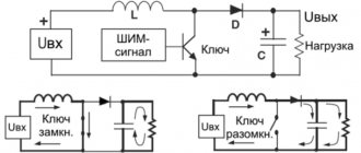
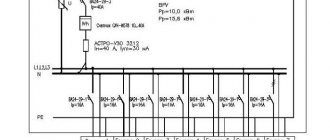
The primary connection diagrams of the transformer substation are determined by the category of consumers and the power of the transformers (Tr). In Fig. Figure 1a shows a single-line diagram of a transformer substation, without busbars on the higher voltage side (6 or 10 kV), with a transformer with a power of up to 100 kVA, with radial power supply, usually used to power loads of category III and, less often, category II. The transformer is turned on and off with a load switch 2, protection against short circuit currents is made in the form of fuses 3. On the low voltage side (380 V) of the transformer, overload protection is carried out by an air circuit breaker of maximum current 4. Power is supplied to consumers through low voltage busbars 6. Protection of outgoing cables 8 of low voltage is made in the form of fuses 3; disconnection is carried out by switch 7. Recently, the switch and fuses are often replaced by an air circuit breaker (circuit breaker) of maximum current, which performs the functions of on/off and protection against overload and short circuit. Current transformer 5 serves to power the measurement circuits (kilowatt-hour meter and ammeter).
Rice. 1. Single-line diagrams of a transformer substation up to 1000 kV•A: a - for consumers of categories III and II; b - for consumers of categories II and I
To power consumers of categories I and II, a so-called two-beam transformer substation is used (Fig. 1b). Power is supplied to the substation through two cable inputs 1 from two different sources with a voltage of 6-10 kV. Operational switching and protection of transformers T is carried out, respectively, using power switches 9. Installation of circuit breakers 10 on the low voltage side, power switches on the high voltage side 9 and an intersection machine 11 allows, in addition to protection against overload and short circuit, automatic switching on of a reserve (ATS) ), stipulated by the rules for the installation of electrical installations (PUE) for category I consumers. The backup power is switched on automatically after an emergency shutdown of one of the supply inputs (ATS on the high voltage side 6-10 kV) or one of the supply transformers (ATS on the low voltage side 380 V). The interruption in the energy supply during automatic transfer does not exceed 1 s, which practically does not disrupt the normal operation of most consumers. Current transformers 13 and voltage transformers 12 serve to power the measurement and protection circuits on the 6-10 kV voltage side.
The secondary winding of the step-down transformer is connected by a star to the output and grounded zero point. The phase-to-phase (line-to-line) voltage of 380 V switches on the power load - mainly electric drive converters, three-phase current motors, etc.; Lighting devices are switched on to a phase voltage of 220 V. Thus, the use of a four-wire system with a linear voltage of 380 V determines the joint power supply of power and lighting loads.
Recently, at large printing enterprises, in-shop complete transformer substations (CTS) with a higher primary voltage of 6-10 kV and a lower one of 380 V, with dry (without oil-filling) transformers with a power of up to 1000 kVA, have become widespread. The package transformer substations include a 630 or 1000 kVA power transformer, switching protective and measuring equipment and feeder devices. High-voltage switching equipment and circuit breakers located in steel cells have plug-in contacts and devices for turning off the circuit breakers when the doors are opened.
Basic principles for choosing a transformer
As a rule, power systems use one or two transformer substations. The use of three transformer substations creates additional capital costs and increases annual operating costs. Three-transformer substations are rarely used, as a forced solution during reconstruction, expansion of a substation, with a separate power supply system for power and lighting loads, or with sudden power supply to variable loads.
Large substations (GPP) mainly use two transformers (two independent power sources), since through such substations it is necessary to provide electricity to consumers of categories I, II and III of power supply reliability.
At different points of receiving electricity at the enterprise at the GPP, as well as when powering the enterprise according to the deep input scheme into the PGV, it is allowed to use one transformer, providing post-emergency power supply to the loads through secondary voltage connections with adjacent substations (PGV, GPZ), with CHP plants or other power plants. For the main power supply of single-transformer PGVs via 35-220 kV lines, it is recommended to connect the nearest substations to different lines or circuits with subsequent use of secondary voltage connections in post-emergency mode.
Single-transformer transformer substations 6-10 / 0.4-0.23 kV are used to power loads that allow power outages for a period of no more than a day, which is necessary for repairing or replacing a failed element (power supply to category III consumers), as well as for power supply consumers of category II, subject to power reservation using jumpers on the secondary voltage or if there is a supply of transformers.
Determination of substation power
Methods for determining electrical loads.
The design of an enterprise's power supply is usually carried out in two stages: the stage of the design assignment (or technical project) and the stage of working drawings. At the design task stage, electrical loads are calculated approximately, for example, according to data on the total installed power of individual consumers (shop departments, etc.). At the stage of working drawings, a final refined calculation of electrical loads is made using specific data on individual receivers of departments, workshops, etc. Determination of design loads is carried out from the lowest to the highest levels of the power supply system for individual design nodes in networks with voltages up to and above 1000 V. Calculation of electrical loads of various nodes of the power supply system is carried out in order to select sections of supply and distribution networks with voltages up to and above 1000 V, number and power substation transformers, bus sections of their distribution devices, switching and protective equipment. The main methods for determining the largest design loads, currently used in design practice, can be divided into two main groups: 1) the method that determines the largest design load Pmax by multiplying the installed power of the consumer Rust by the demand coefficient ks < 1, i.e. with. P, = Rust x; 2) methods that determine the largest design load either by multiplying the value of the average load Psr by the coefficient of increase in the average load, i.e. Pmax = Rsrkun, or by adding to the value of the average load a certain value ∆c, characterizing the deviation of the largest load from the average, i.e. Рmax == Рср + ∆с. The first group includes the method of determining the design load based on installed capacity and demand factor, which is discussed in detail below. This method, compared to the methods of the second group, is approximate and is used mainly at the stage of the design task. A special group consists of methods for determining design loads based on specific production indicators, namely, specific electricity consumption per unit of production for a given volume of production for a certain period and specific power per unit of production area. Data on specific production indicators, accumulated on the basis of long-term experience in the design and operation of electrical installations for various purposes, are given in reference literature.
Types of TP
There are many types of distribution transformer substations, varying in power, location and design. Among them the following main types can be distinguished:
- Transformer substations with a capacity of up to 40 kW for power supply of small objects.
- Powerful distribution complexes used to supply energy to urban areas and large enterprises.
- Complete transformer substations or package substations, built on a modular principle (bl.
Additional information: PTS, in turn, are divided into throughput and dead-end, which are part of the distribution network system.
According to their location, all known types of transformer substations are divided into closed and open station ones. An example of the second type is pole or pole transformer converters.
Power selection in industrial networks
The choice of power in the networks of industrial enterprises is carried out according to the following principles:
- the specific power of transformers is selected based on the recommendations of the specific density of the design load and the total design load of the installation;
- the number of substation transformers and their rated power are determined in accordance with the Guidelines for the design of reactive power compensation in electrical networks of industrial enterprises 3 (see also section 4.3);
- the choice of transformer power should be made taking into account the recommended load factors (Table 3.2) and permissible emergency overloads of transformers (Table 3.3);
- in the presence of standard load circuits, the choice should be made in accordance with GOST 1420985 and taking into account reactive power compensation in networks up to 1 kV.
Transformer power selection
In general, the choice of transformer power is made based on the following basic initial data: the calculated load of the power supply facility, the duration of the maximum load, the rate of load growth, the cost of electricity, the load capacity of transformers and their economical loading.
The main criterion when choosing a unit power, as well as the number of transformers, is the minimum reduced costs, obtained on the basis of a technical and economic comparison of options.
Approximately, the choice of unit power of transformers can be made according to the specific density of the calculated load (kVA/m2) and the total calculated load of the facility (kVA).
With a specific load density of up to 0.2 VA/m2 and a total load of up to 3000 kVA, it is advisable to use transformers 400; 630; 1000 kVA - with secondary voltage 0.4/0.23 kV. When the specific density and total load are higher than the specified values, transformers with a capacity of 1600 and 2500 kVA are more economical.
However, these recommendations are not sufficiently substantiated due to rapidly changing prices for electrical equipment, and in particular, TP.
In design practice, TP transformers are often selected based on the design load of the facility and recommended coefficients.
An important factor when choosing the power of transformers is the correct consideration of their load capacity. The load capacity of a transformer is understood as the totality of permissible loads, systematic and emergency overloads based on the thermal wear of the transformer insulation. If you do not take into account the load capacity of transformers, then you can unreasonably overestimate their rated power when choosing, which is not economically feasible.
At the vast majority of substations, the load on transformers varies and remains below nominal for a long time. A significant part of transformers are selected taking into account post-emergency operation and therefore they normally remain underloaded for a long time. In addition, power transformers are designed to operate at a permissible ambient temperature of +40 °C. In fact, they operate under normal conditions at ambient temperatures up to 20... 30 °C.
Consequently, a power transformer can be overloaded at a certain time, taking into account the circumstances discussed above, without any damage to its service life (20...25 years).
{xtypo_quote}Based on studies of various operating modes of transformers, GOST 1420985 was developed, regulating permissible systematic loads and emergency overloads of general-purpose power oil transformers with a power of up to 100 mVA inclusive with types of cooling M, D, DC and C, taking into account the cooling temperature of the medium.{/xtypo_quote }
The temperature of the cooling medium for determining permissible systematic loads is taken as an equivalent value for a given area, calculated in accordance with [24]. For regional cities of Russia, the equivalent temperature is in the range: 9.4...11 °C - annual, 3.4...6.7 °C - winter and 15.1...17.9 °C - summer. When determining permissible emergency overloads, the temperature of the cooling medium is taken at the time the emergency overload occurs.
To determine systematic loads and emergency overloads in accordance with, it is also necessary to know the initial load preceding the overload and the duration of the overload.
This data is determined from the actual original load curve (apparent power or current) converted into a thermally equivalent rectangular two or multi-stage curve.
Due to the need to have a real initial load schedule, calculation of permissible loads and overloads in accordance with can be performed for existing substations.
At the design stage of substations, you can use standard load diagrams or, in accordance with the recommendations also proposed in, select the power of transformers according to the conditions of emergency overloads according to Table. 3.3.
Then for substations where emergency overload of transformers is possible (two-transformer, single-transformer with backup connections on the secondary side), if the design load of the object Sp and the permissible emergency overload coefficient Kzav (Table 3.3) are known, the rated power of the transformer is determined as It should also be noted that the load operation of a transformer in excess of its rated power is permitted only if the transformer cooling system is in working order and fully switched on.
As for typical graphs, today they are developed for a limited number of load nodes.
Partially typical schedules of individual types of consumers (municipal and agricultural) have been processed and, for practical convenience, summarized in table. 3.4, 3.5 [25].
These tables, in abbreviated form, respectively indicate the intervals of permissible loads and emergency overloads of transformers with natural oil cooling, voltage 10/0.4 kV, power up to 630 kVA for some types of consumers, taking into account the climatic conditions of Russia.
According to the table 3.4 for the required type of load, the interval of the minimum and maximum limit of the permissible systematic load of the transformer (Samm...Samg) is found, in which the value of the calculated load of the transformer Sp is located (for transformers, determines the rated power of the transformer according to the permissible load for normal operation of the substation.
According to the table 3.5 for the corresponding type of load, the rated power of the transformer is established according to the permissible emergency load based on the condition: Depending on the possible operating modes of the transformer, its power is selected according to table. 3.4 or according to table. 3.4, 3.5.
Since the choice of the number and power of transformers, especially consumer substations 6-10/0.4-0.23 kV, is most often determined by economic factors, taking into account reactive power compensation in consumer electrical networks is essential.
By compensating for reactive power in networks up to 1 kV, it is possible to reduce the number of 10/0.4 transformer substations and their rated power.
This is especially important for industrial consumers, in networks up to 1 kV in which significant amounts of reactive loads have to be compensated. The existing methodology for designing reactive power compensation in electrical networks of industrial enterprises involves selecting the power of compensating devices and, at the same time, the number of substation transformers and their power.
Thus, taking into account the above, as well as the complexities of direct economic calculations, rapidly changing cost indicators for the construction of substations and the cost of electricity, the choice of power transformers when designing new and reconstructing existing consumer substations 6-10/0.4-0.23 kV can be carried out as follows way: