What is the marking of smd resistors
SMD resistors are permanent parts that are required for surface mounting on a board. If we compare smd resistors and metal film resistors, the former will be several times smaller, but there are also those that are larger, which is why there is a marking of smd resistors. They also differ in shape; there are square, rectangular and round and even oval. Carefully studying the SMD resistor markings, you can note that the markings can be digital or alphabetic.
The main difference between SMD resistors is the presence of small contacts that are inserted into the printed circuit board. Let's look at why resistor markings are needed.
Why do we need resistor markings?
Considering the fact that SMD resistors are small in size, they cannot be color coded, so manufacturers have developed a different marking method. As a rule, the designation of smd resistors contains three or four numbers; letters may be present.
- Digital marking of resistors is necessary in order to indicate the numerical value of the resistance of the resistor, the last digit is a multiplier. It can also indicate the power that must be raised to 10 to get the final result. For example, resistance can be determined this way: 450 = 45 x 10 equals 45 Ohms.
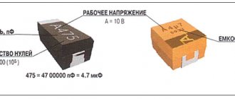
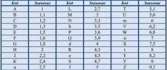
- If the marking is EIA-96, then this means that the resistors are high precision. This standard is intended for resistors that have a small resistance of 1%. This marking system has three elements: 2 numbers that indicate the denomination code, and the letters are a multiplier. The numbers are a code that gives the resistance number. For example, code 04 may indicate 107 ohms.
For convenient calculation, a calculator is used that will help you quickly find the resistance value. To calculate, you need to enter the code that is on the component and the resistance will immediately appear below. This calculator is suitable not only for the standard. To more accurately check the resistance, it is best to use a multimeter for calculations. Read here which is the best multimeter to choose.
What characteristics does it show?
The most important characteristics of the parts are the value of the nominal resistance, the tolerance on the value and the temperature coefficient. Any of these characteristics is related to the power of SMD resistors and the resistance between it and the ambient temperature. In some areas, even noise characteristics are taken into account.
Important! Component characteristics include stability, voltage, resistance dependence and frequency parameters.
To understand this issue in detail, you need to carefully study all the characteristics:
- The value of the nominal resistance. The tolerance on the nominal resistance value is specified as a percentage. This value indicates the resistance of the resistor under external influences on it.
- Temperature. As a rule, the natural temperature is +20°C and there should be normal atmospheric pressure. SMD resistors are produced with a tolerance for nominal resistance ranging from ±0.05% to ±5%.
- Accuracy. The most accurate resistors can be considered those that are calculated using the formula TKS=DR/(R*DT). DR means the change in resistance when the temperature changes by the amount DT, R is the nominal value of the resistance.
If the components can be calculated using this formula, then this means that they have the highest accuracy.
Calculation of the quenching resistor
In communication equipment circuits, it is often necessary to supply the consumer with less voltage than the source provides. In this case, an additional resistance is connected in series with the main consumer, at which the excess voltage of the source is extinguished. The video shows a simple calculation of a resistor for an LED.
It will be interesting➡ How is parallel and series connection of resistors different?
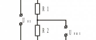
This resistance is called damping resistance. The voltage of the current source is distributed over sections of the series circuit in direct proportion to the resistance of these sections. Let's consider the circuit for switching on the damping resistance:
- The payload in this circuit is an incandescent light bulb, designed for normal operation at voltage Ul = 80 V and current I = 20 mA.
- The voltage at the terminals of the current source U=120 V is greater than Ul, so if you connect a light bulb directly to the source, then a current exceeding normal will pass through it and it will burn out.
- To prevent this from happening, a damping resistance R extinguished is connected in series with the light bulb.
Calculation of the value of the damping resistance at given values of the consumer current and voltage comes down to the following:
– the amount of voltage that must be extinguished is determined:
Next, you need to calculate the power released at the damping resistance using the formula
Knowing the resistance value and power consumption, choose the type of damping resistance
Types of SMD resistor markings
An important characteristic of resistors is the size. In simple words, this is the size, length and width of the body. It is by taking these elements into account that it is possible to select the appropriate board layout.
Reference! All sizes of SMD resistors in the documentation are indicated using special numbers and letters. The first numbers can indicate the dimensions, which are given in millimeters, the second pair of characters can indicate the width, also in millimeters.
Let's look at some typical resistor sizes and their decoding by numbers:
- SMD resistors 0201: length = 0.6 mm, width = 0.3 mm, height = 0.23 mm. The nominal values are 0 Ohm, 1 Ohm - 30 MOhm. Power is only 0.05 W, voltage maximum 50 V.
- SMD resistors 0402: length = 1.0 mm, width = 0.5 mm, height = 0.35 mm. The nominal values are 0 Ohm, 1 Ohm - 30 MOhm. Power is only 0.05 W, voltage maximum 100 V.
- SMD resistors 0603: length = 1.6 mm, width = 0.8 mm, height = 0.45 mm. The nominal values are 0 Ohm, 1 Ohm - 30 MOhm. Power is only 0.01 W, voltage maximum 100 V.
- SMD resistors 0805: length = 2.0 mm, width = 1.2 mm, height = 0.4 mm. The nominal values are 0 Ohm, 1 Ohm - 30 MOhm. Power is only 0.125 W, voltage maximum 200 V.
- SMD resistors 1206: length = 3.2 mm, width = 1.6 mm, height = 0.5 mm. The nominal values are 0 Ohm, 1 Ohm - 30 MOhm. Power is only 0.25 W, voltage maximum 400 V.
- SMD resistors 2010: length = 5.0 mm, width = 2.5 mm, height = 0.55 mm. The nominal values are 0 Ohm, 1 Ohm - 30 MOhm. Power is only 0.75 W, voltage maximum 200 V.
- SMD resistors 2512: length = 6.35 mm, width = 3.2 mm, height = 0.55 mm. The nominal values are 0 Ohm, 1 Ohm - 30 MOhm. Power is only 1 W, voltage maximum 400V.
Calculation of the quenching resistor
In communication equipment circuits, it is often necessary to supply the consumer with less voltage than the source provides. In this case, an additional resistance is connected in series with the main consumer, at which the excess voltage of the source is extinguished. The video shows a simple calculation of a resistor for an LED.
It will be interesting➡ How to read the designation (marking) of resistors
This resistance is called damping resistance. The voltage of the current source is distributed over sections of the series circuit in direct proportion to the resistance of these sections. Let's consider the circuit for switching on the damping resistance:
- The payload in this circuit is an incandescent light bulb, designed for normal operation at voltage Ul = 80 V and current I = 20 mA.
- The voltage at the terminals of the current source U=120 V is greater than Ul, so if you connect a light bulb directly to the source, then a current exceeding normal will pass through it and it will burn out.
- To prevent this from happening, a damping resistance R extinguished is connected in series with the light bulb.
Calculation of the value of the damping resistance at given values of the consumer current and voltage comes down to the following:
– the amount of voltage that must be extinguished is determined:
Next, you need to calculate the power released at the damping resistance using the formula
Knowing the resistance value and power consumption, choose the type of damping resistance
Examples of decoding digital markings of SMD resistors
To quickly understand the decoding of SMD resistor markings, you need to consider several options.
Resistor 103
To calculate resistance, it is worth understanding the numbers from the very beginning. If we take resistor 103, then the first two digits will indicate the numbers, and the third digit will be the number of zeros, so it turns out that 10 and 3 will be 10,000 ohms. Such components may have a small error, which ranges from 2 to 10%.
Resistor 1206
In this case, the resistance is calculated in a different way. The first three digits are the number, and the last number of zeros or, as they say, the power to which the factor 10 must be raised. So, let’s calculate the value of the element with characteristic 1206:
120 * 10 to the 6th power = 2.985984 × 10^12 kOhm with an error of 1%
Resistor 2r2
If the component has a fractional value, then the letter R is placed in the code instead of a dot. In this case, the calculation for the resistor is 2R2 = 2.2 Ohm.
The most difficult thing to calculate is alphabetic and numeric codes, since numbers contain one information, and letters act as a multiplier. For quick calculations, there are special online calculators that help determine the resistance of an SMD resistor. There is also a marking table that is useful in calculations.
How to determine and select the power of a resistor (resistance)
Radio amateurs often have to deal with resistors, and if this is not the first time, then most already know how to determine the characteristics of a circuit element from the markings. But not everyone can do this, and besides, even experts often have to rack their brains when faced with, for example, a printed circuit board with SMD components.
It makes sense to trace the step-by-step evolution of resistors and their markings. First, consider the simplest of them, and only then move on to complex and high-tech SMD resistors.
What kind of lighting do you prefer?
Built-in Chandelier
So, there are three types of similar elements. These are Soviet resistors, which are still used today, however, they are modern - i.e. those that have multi-colored stripes, and of course SMD components.
Soviet resistors
Of course, no matter how hard you try, you can’t do without Soviet electronics, and therefore it makes sense to study the markings of such resistors.
At first glance, you can visually try to determine the maximum dissipation powers of these elements.
The image above shows the difference in their sizes. Starting from the top their power is:
The first two resistors are 1W. and 2W. marked with the letters MLT-1 and MLT-2 - this is the most widely known variety. MLT is an abbreviation for Metal Film, Lacquered, Heat Resistant Element.
The rest can only be determined by their dimensions; there are no markings on them. Naturally, the larger the resistor, the greater the power dissipation - the laws of physics have not been canceled by anyone.
So it’s quite simple to identify Soviet-era resistors by their markings, having learned their technical characteristics, which, of course, cannot be said about elements with multi-colored stripes applied to them.
Modern resistors
To determine the characteristics of this element, you first need to unfold it so that the golden or silver stripe is on the right hand. If there is none, you need to look at which side several stripes are closest to and turn them around so that they are on the left hand.
Next, the color of the first two stripes is determined, and each of them has its own digital designation. The strip can be:
Another bar will show the number of zeros needed to be added to the numbers resulting from the first two. So, if the stripe:
- Black – no zeros;
- Brown – 0 (1);
- Red – 00 (2);
- Orange – 000 (3);
- Yellow – 0000 (4);
- Green – 00000 (5);
- Blue – 000000 (6);
- Purple – 0000000 (7);
- Gray – 00000000 (8);
- White – 000000000 (9).
Provided that there are not 3, but 4 stripes on the resistor (not counting the silver or golden stripes), then the first three are numbers, and the 4th is the number of zeros.
Usually there are 3 or 4 stripes on the element, but sometimes 5-6. You should start with a wider one, but sometimes the manufacturer does not mark it. It will be located closer to the conclusion.
| Resistor type | Diameter, mm | Length, mm | Power dissipation, W |
| Sun | 2,5 | 7,0 | 0,125 |
| ULM, VS | 5,5 | 16,5 | 0,25 |
| Sun | 5,5 | 26,5 | 0,5 |
| 7,6 | 30,5 | 1 | |
| 9,8 | 48,5 | 2 | |
| 25 | 75 | 5 | |
| 30 | 120 | 10 | |
| CMM | 1,8 | 3,8 | 0,05 |
| 2,5 | 8 | 0,125 | |
| MLT | 2 | 6 | 0,125 |
| 3 | 7 | 0,125 | |
| 4,2 | 10,8 | 0,5 | |
| 6,6 | 13 | 1 | |
| 8,6 | 18,5 | 2 |
Expert opinion
Viktor Pavlovich Strebizh, lighting and electrical expert
Any questions ask me, I will help!
In this case, an additional resistance is connected in series with the main consumer, at which the excess voltage of the source is extinguished. If there is something you don’t understand, write to me!
SMD resistor marking table (code/nominal/size/power) table
SMD resistors marking table:
| Code | Nominal, W | Size | Power V |
| 0402 | 0.062 | Length 1.0 ±0.1, width 0.5 ±0.05, height 0.35 ±0.05 | 100 |
| 0603 | 0.1 | Length 1.6 ±0.1 width 0.85 ±0.1 height 0.45 ±0.05 | 100 |
| 0805 | 0.125 | Length 2.1±0.1 width 1.3 ±0.1 height0.5 ±0.05 | 200 |
| 1206 | 0.25 | Length 3.1 ±0.1 width1.6 ±0.1 height0.55 ±0.05 | 400 |
| 1210 | 0.33 | Length 3.1 ±0.1 width 2.6 ±0.1 height0.55 ±0.05 | 400 |
| 2010 | 0.75 | Length 5.0 ±0.1 width 2.5 ±0.1 height 0.55 ±0.05 | 400 |
| 2512 | 1 | Length 6.35 ±0.1 width 3.2 ±0.1 height 0.55 ±0.05 | 400 |
| 0075 | 0,02 | Length 0.3 Width 0.15 | 100 |
| 01005 | 0,03 | Length 0.4 Width 0.2 | 100 |
| 0201 | 0,05 | Length 0.6 Width 0.3 | 100 |
| 1218 | 1 ; 1,5 | Length 3.2 Width 4.8 | 150 |
| 1812 | 0,5; 0,75 | Length 4.5 Width 3.2 | 200 |
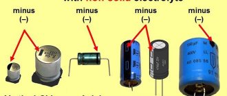
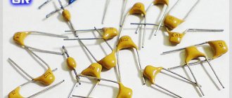
Today there are a huge number of highly specialized parts that differ in their advantages and disadvantages. For example, there are capacitors that can operate at high temperatures, almost 230 °C, there are those that are designed to work in aggressive environments, and milliohm chip resistors have also appeared. There are capacitors that can only be used in certain circuits. The table above indicates standard options, but actual power dissipation may vary.