Why is there a phase and a neutral, but the socket does not work?
When one power point does not work, the cause may be a loose connection or melted insulation. If during a visual inspection the cover is melted and the socket does not function, then the contact wire has burnt out. ... The problem may be in the wire itself, then you need to inspect the cable, check the condition of the core and insulation.
Interesting materials:
How to set up USB on Samsung phone? How to set up VKontakte notifications on your phone? How to set up WhatsApp on your phone? How to adjust the sound on your phone? How to learn to quickly type text on your phone? How not to lose contacts when changing your phone? How to update Android on ASUS ZenFone 5? How to update Yandex on your phone? How to update the play market on an HTC phone? How to upgrade your silicone phone case?
Splitting three-phase wiring in an apartment
To turn a three-phase network into a single-phase network, it is necessary that a neutral wire and grounding be added to each wire going to a separate apartment.
Ideally, the entire three-phase network has only one zero; more neutral wires are simply not required. The neutral wire is a neutral conductor where there is no voltage. In a phase-phase pair of wires, the voltage is 380 V. If there are no connected devices in a three-phase network, there is no voltage on the neutral conductor.
Below you can use the online calculator to calculate the cost of designing power supply networks:
Determining the phase correctly: color and numbering
To be honest, I didn’t think much about the phases when I was doing the wiring at my dacha. My father also did not pay attention to this; in those days, all the wiring was almost the same, with cracked rubber insulation. However, when I decided to start electrifying the economy and assemble a panel for three phases, I, willy-nilly, learned quite a few facts about the history of electricity in our country.
What color is the phase?
The fact is, in the Soviet Union, phase wires were yellow, red or green . After the disappearance of the Union from the world map, the colors changed to brown, black and gray . However, this fact has absolutely nothing to do with the colors of the flags. The fact is that European standards have been adopted regarding wire marking. The last listed color range is distinguishable for people with visual impairments. But what united us and Europe for quite a long time was that our earth and neutral were always the same color - yellow-green earth and blue (light blue) neutral .
Having remembered the last thing that the neutral wire is blue or blue (light blue), and the grounding wire is green with a yellow stripe , we logically understand that the phase will be any other remaining color , we confidently connect the wires for the next generations, regardless of future revolutions and tremors of the world. This is the answer to the question of how to connect three phases.
But in other countries the wire markings are different. As soon as you think about it, you immediately appear to board an armored car and shout loudly: “Electricians of all countries - unite!”
Why number the three phases?
For a single-phase circuit, where there is one phase, there is no point. But for a three-phase transmission line, let’s number it, so to speak, for the future according to the sequence of colors of the cable leading to the house. Pressing yourself against the six-meter ladder and connecting the wires coming out of the hole in the wall of the house with nuts to the air, do not forget to shout:
“The first phase is the brown wire! The second phase is the black wire! The third phase is a gray wire!
In the same sequence, it is necessary to connect the wires to the built-in circuit breaker. A bold felt-tip pen for numbering would be helpful.
Next to the electrical panel, be sure to hang a framed picture with a complete electrical diagram, with the numbering of each circuit breaker, and the color scheme of the wires. I think that an evacuation plan will not be required in this case.
Yes, I still haven’t answered the question why numbering is needed. I don't know yet. What if my son buys an electrical appliance exclusively for a three-phase circuit with instructions where the phases are indicated by numbers? Then you won’t have to climb the seven-meter ladder again, having completely forgotten by that time both colors and numbers.
Main differences
A common factor is the number of wires and voltage. This is where the differences end. A single-phase connection is characterized by connecting two/three wires (phase, neutral, ground) to the house or apartment. Typically the conductor cross-section is 4-6 mm2. And in the house they use 1.5-2.5 mm2 wiring
However, it is limited in terms of maximum power consumption, which should not exceed ten kW. It may be difficult to connect consumers designed for three-phase voltage. When connecting, additional devices will be required, and you also need to be prepared for a loss of power.
Typically, three phases are supplied to an apartment building, and only one phase is supplied to each apartment. At the same time, they try to distribute the load proportionally, eliminating phase imbalance. They also take into account that 220V voltage is less dangerous than 380V, from a safety point of view.
If the consumer plans to connect to an electrical network with an allocated power of more than ten kW, it is necessary to use three-phase voltage.
The difference in this case lies in the connection of a cable with four/five cores to the house or cottage. What is the difference from a two-wire connection? In this case, the consumer receives two voltage values: linear will be equal to 380 V, and phase - 220 V.
Measurement is carried out as follows. Phase voltage is measured between the neutral conductor and each phase alternately, linear voltage is measured between phases.
The figure below shows how to measure phase and line voltage.
It should be taken into account that in cottages where the installed power exceeds ten kilowatts, but there is no three-phase load, the active power should be distributed evenly between the phases.
This is the difference with a single-phase connection; there is no need to distribute power.
The figure below shows the connection diagram for a single-phase load evenly distributed over three phases and the formula for the dependence of line voltage on phase voltage.
In this case, there is no need to use switching equipment (automatic machines, starters) for high currents. More often, a three-phase network is used for industrial enterprises, shops, and office premises.
Why powerful equipment is often three-phase
The main factor in using a three-phase connection to a powerful load is the transmission of high power with a smaller cable cross-section, relative to a single-phase one. This significantly reduces the cost of electrical networks and switching devices.
This type of electricity supply is used for industrial enterprises, workshops, and farms. That is, for organizations where the main consumers are three-phase electrical installations.
These can be electric motors, powerful drying units, stationary welding equipment, metalworking and woodworking machines, etc.
Advantages and disadvantages
Each of the networks, single-phase and three-phase current systems, has its own advantages, but is not without its disadvantages.
Let's consider the main advantages for the 220V line:
- They are not complicated. A person with minimal knowledge of electrical engineering can understand the circuit.
- Two wires are enough for connection (if grounding is not used). This greatly simplifies the network.
- Relatively low dangerous voltage.
The main disadvantage is high currents with high power consumption, so for powerful devices (7-10 kilowatts or more) single-phase connection is practically not used. Now let’s look at how differs from a 1-phase network.
For 380 V networks:
- The connected power is limited only by the cross-section of the conductors and the power allocated by the electrical networks.
- Can be used to provide electricity to any objects.
- It is possible to “select” a phase with the best parameters to power important single-phase consumers; for this, phase switch relays are used.
Disadvantages include:
- Expensive cables and switching equipment.
- Dangerous voltage.
How is the electrical wiring arranged in the apartment? General principles
Let's compare electric current with water current. Water flows through the pipe to the turbine and, rotating it, flows out through the second (outgoing) pipe. If the second pipe is blocked, the water flow will stop and the turbine will stop rotating.
Electric current works in exactly the same way.
- There is a “feed pipe” here - a phase wire, when touched, the voltage indicator lights up.
- There is a “discharge pipe” - a working zero, through which the current “flows” from the “turbine” - the device.
If, for example, the working zero is broken, the current in the circuit disappears. But the voltage on the device remains (the turbine remains flooded with water, and as soon as an outflow path appears, the “water” will flow again).
In reality, everything is somewhat more complicated. From the electrical panel to the apartments there is not one phase wire, but three. Returning to our comparison: water flows through three pipes, and flows back through one. This is a standard five-wire circuit: three phases and a working zero. There is also a grounding wire, but grounding is a separate discussion. For now, let's imagine that he is not there. Between any different phases the voltage is 380 volts, between any phase and the neutral wire (“zero”) 220 volts. Phase, neutral and grounding are the same things we started with and what comes to your apartment.
Photo: Depositphotos
As a rule, city dwellers deal with the following wiring diagram.
Each entrance is powered by a cable consisting of 4 or 5 cores. Three phases and zero are always present; in old houses there may not be a separate grounding wire.
In the electrical panel of the house there are circuit breakers that power the “apartment” lines. Usually one for each entrance. The machines de-energize the line in the event of a short circuit or overload (if the power of electrical appliances exceeds the permissible limit).
Four-core cable connected:
- three wires - to three terminals of the circuit breaker;
- zero conductor - to the zero terminal or (in old houses) directly to the electrical panel housing.
The cable is laid through the basement and from there rises up the riser, passing through the electrical distribution panels located on the floors.
Attention! From this moment the practical part begins. The electrical equipment that residents deal with begins with the electrical panel.
Here you can see thick insulated conductors stretching from bottom to top, from which there are branches to the switchboard equipment. The specific switching method differs depending on the type of house, so I will talk about a kind of conditional option. What is important for understanding is not the specific method, but the principle.
Photo: Depositphotos
Three phases and zero pass through the shield. For simplicity, we omit grounding.
To operate household electrical appliances, you need one phase and a zero (remember: a water supply pipe and a discharge pipe?). Consequently, one of the phase wires has a section where the insulation is removed from it to connect the wires supplying current to the apartments.
The connection point can be either open (for example, the bare core is simply attracted by a terminal to the bus from which the wires supplying the apartments come off) or closed (for example, a plastic “nut”, inside of which the outgoing wires are connected to the power core, again with a terminal) . If the phase wire is accidentally connected to the neutral wire, a short circuit will occur; phase contact with the body of the electrical panel is fatal for the person who touches it (this is the same as touching a bare wire). Therefore, the phases are always isolated from the housing.
But the neutral wire, on the contrary, is often connected to the panel body.
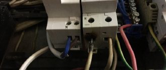
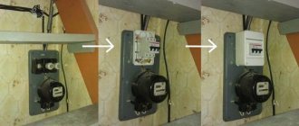
Let's assume that we have three apartments on the floor. To each of them, one phase and one neutral conductor extend from the busbars. Both wires are connected to the input terminals of the RCD - a residual current device (in old houses there may not be one at all, for example, in my house built in the 80s there is no RCD). Two wires entered from above, two came out from below to the electric meter. If necessary, the RCD can be turned off, de-energizing the electric meter and the entire apartment at once.
Photo: Depositphotos
From the meter, the phase wire goes to the inputs of single-phase circuit breakers, connecting with special jumpers to the inputs of all machines (if necessary, you can use them to “break” a phase, de-energizing the desired line in the apartment), while the neutral wire is connected to a block or terminal block (usually it is located nearby with machine guns or above them).
All electrical wiring of the apartment is divided into several lines or groups. Most often this is a socket group, a light group (powering chandeliers) and a line for an electric stove. It happens differently, but I am considering a typical “average” scheme. Each line receives a phase and a zero from the electrical panel. Relatively speaking, from the apartment to the switchboard, a three-core wire from each group is stretched in the ceilings.
The wires go down to the switchboard through channels laid in the wall and are connected according to the standard scheme:
- one core - to the output of the circuit breaker (on top of the machine - input, below - output);
- the second - to one of the free terminals of the zero block or terminal block.
That is, on the one hand, the supply neutral wire from the meter approaches the block, and on the other, the outgoing wires to the apartment lines. It’s the same with automatic machines, only here each line is connected to its own separate automatic machine.
Automatic switches Photo: Sid74, pixabay.com
We all deal with circuit breakers if we need to de-energize an apartment. Or, due to excessive load, the plugs were “knocked out” - although the plugs actually remained in very old houses, many call circuit breakers that way. Then we go out onto the landing and turn on or off the circuit breakers.
So, two wires go into the apartment: zero from the zero block and phase from the circuit breaker. And so three times, three groups: sockets, lighting and electric stove.
In the apartment, the wire that powers the electric stove (it is easy to identify: it is thicker than the others) goes, without branching, to the stove socket. The other two groups branch out into a series of lines going to light fixtures and outlets. The light wires are laid in the ceilings, partly in the walls: where the wire goes down to the switch. Rosettes can run in different ways; in modern houses, as a rule, they also go down from the ceiling inside the wall to each outlet. It’s different in houses built from the 60s to the 80s. General guideline: location of sockets. Typically, the wires run down from above where the sockets are located high (about a meter) above the floor. If they are installed above the baseboard, the wires are most likely laid in the floor.
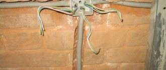
Naturally, the wiring is not one solid wire. The lines branch and connect many times. All this happens in junction boxes embedded in the wall (plastic, in old houses - metal) or simply in wall cavities under the ceiling. Usually such places are covered with metal covers and can be easily identified under the wallpaper by tapping.
In most cases, all sockets are powered from one circuit breaker, except for one: located in the switch block of the bathroom (often the light in the kitchen is also turned on here). This socket is powered from the “light” machine along with the rest of the lighting.
If an additional outlet is installed in the bathroom, it can be connected to any group, and also have a separate circuit breaker altogether. If you need to carry out any manipulations with it, do not rely on chance. Make sure you actually turn it off. Plug in the table lamp and turn off the machine while the lamp is on. Has the lamp gone out? You've disabled what you need!
Photo: chrischesneau, pixabay.com
However, “the instructions are written in blood” - so be sure to check that there is no voltage using a voltage gauge (indicator). Please note that many sockets are protected against “unauthorized insertion” of foreign objects by children. The sockets of the socket are covered with a shutter, which opens when two pins are inserted at the same time (as happens when the plug is turned on). So, when using the indicator, make sure that you actually reach the terminals. It is best to use an indicator to check the socket with the cover removed.
It may also turn out that there are several outlet groups in the apartment, powered from different machines. For example, a separate line can go to kitchen or bathroom sockets, or separate lines can be laid for each room (a fashionable scheme, especially when installing the wiring yourself). There are also modifications to a seemingly standard circuit - for example, forced ones when troubleshooting.
So if you are not sure that you understand the electrical wiring correctly, it is better to contact a specialist. Although they sometimes shrug their shoulders when they see the creation of an unknown electrician...
Tags: apartment wiring, wiring diagram
