Electricity was a luxury a hundred years ago, but today it is a vital necessity for any person. After all, many things depend on electricity - the Internet, lighting, the operation of household appliances, and therefore food storage and cooking. Also, air conditioners and ventilation systems, and often space heating, and many other, smaller but necessary electrical appliances rely on electricity.
But electricity is not taken into the house just like that. Energy supply companies only deliver it to the meter, and then the owners must distribute the lines throughout the house. And this is where the difficulties begin, because without knowledge it is not so easy to design wiring in an apartment. After all, not everyone knows what parts the electrical network consists of, and only learn about circuit breakers and grounding loops when something breaks.
This article explains in detail the step-by-step process of creating your own wiring line from the panel to the farthest outlet in the apartment, so that everyone, after reading it, can evaluate their strengths.
*(It’s not difficult to do the wiring yourself if you have a clear plan)
When to change wiring
Of course, new wiring will be required in a newly completed apartment, but buying a new home is not the only reason when you should think about changing the wiring.
It is also worth paying attention to how electrical appliances are connected today in an existing apartment, in which the electrical network was located in accordance with established GOSTs. After all, then there was no expectation that very soon there would be so many electrical appliances that would be constantly in use, and they would constantly not have enough sockets.
Because of this deficiency, extension cords and new lines begin to appear in the house on top of the walls, which is not only aesthetically unpleasant, but can also be dangerous if you connect a lot of equipment at once. This is especially true for those situations where tees or even several tees at once are used, connecting to each other and to one unfortunate outlet. Such piles are a direct road to short circuit and fire.
*(The appearance of a similar picture in the house is a clear hint that it’s time to change the wiring).
Or another problem may arise - aluminum wires. Such, for the sake of economy, were often used in the construction of high-rise buildings, when there was a special boom in their construction several years ago. Aluminum conducts electricity well, but it has a couple of serious disadvantages:
- Aluminum is too soft. That is, it is very easy to deform under external influence, and it can even break completely. And for the same reasons, repairs are not easy to carry out, since it will not be possible to properly change only a section.
- Chemical reactions. When current constantly passes through aluminum, it provokes electrochemical reactions in the wires, which increase their fragility. And after 15–20 years, which is a very short period of time for electrical wiring, the wires can become so fragile that sudden breaks begin to appear in them. And if you try to repair the wire and make new twists, nothing will work - the wires will break in your hands.
- Corrosion. Aluminum is not as resistant to moisture as we would like, and then even a small amount of water will lead to electrocorrosion. And even if the wires look intact on the outside, they may already be so damaged on the inside that even a small load will cause them to break or spark.
*(To ensure wiring lasts as long as possible, it is better to choose copper rather than aluminum)
To sum up the issue with aluminum: if the wiring is made of this metal, it is better to completely replace it with copper, which is much more reliable. Of course, copper, due to its properties, is more expensive. However, wiring is not done annually, but once every few decades, so there is no need to save money here.
Cable
A cable is several insulated wires in a common protective insulation.
The number of wires in the cable may vary. For household electrical wiring, two-, three- and four-core cables with a cross-section from 2.5 to 4 mm are used. Wires and cables for household electrical wiring are made of copper or aluminum. In older houses that are more than 15 - 20 years old, aluminum wiring was previously used. Modern houses are equipped with copper cables: with the same wire cross-section, copper cables can withstand a large electrical load. In addition, copper cables are more flexible and less susceptible to oxidation.
Important: try to avoid connecting copper and aluminum wires. At the point of such contact, a chemical oxidation reaction occurs, releasing a large amount of heat. Possible fire. Use cables made of the same material.
NYM cable
High-quality German cable consisting of 1-5 cores. It is used for laying lighting and power networks both indoors and outdoors. Its distinctive feature is a high degree of security. This cable is also moisture and heat resistant, but does not like sunlight, so it must be protected from direct rays.
VVG cable
Cable with excellent insulation characteristics. It consists of one core, making it convenient to install inside walls. Most often, VVG is used when independently installing or replacing electrical wiring in an apartment. The service life of such a cable is at least 30 years.
Why do you need to change the wiring?
When it becomes clear that the wiring is not made as desired or from the wrong material, the question immediately arises as to whether it is really necessary to replace the wiring in the entire system. After all, you just want to repair and improve, and not change everything at once, even though the second option is often cheaper than the first. And these are not all its advantages.
To answer this question, it's first worth looking at the system that was used to wire homes in the past and likely continues to work in most homes today.
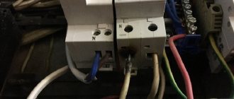
Wiring systems: modern and outdated
It’s worth starting with grounding loops, which were not considered a necessary attribute. All networks were created according to the same TN-C scheme - with it, the working zero and ground were taken to one wire at the station distributing electricity. This method has advantages:
- Easy to install.
- Material consumption is significantly reduced.
*(Using this diagram you can easily understand how the TN-C circuit works)
All sockets were entangled with phase and neutral wires, tying them with the others into knots. And because of this, with excessive load, the risk of a short circuit increased significantly. This also created problems for the operation of the RCD. Due to the high risk, such a system is no longer used and it is recommended to replace it with something more modern - TN-S or TN-CS circuits.
The first is most often used in private homes, where there is its own grounding. But it also occurs in high-rise buildings where there are grounding buses. And here they must:
- Sealed by welding.
- Go from the grounding outside to all apartments and entrances.
However, most often in large houses with many apartments, the TN-CS scheme is still found. In it, the grounded neutral is divided into two conductors:
- Zero worker.
- Zero protective.
The separation occurs directly in the shield, which is located in the entrance.
Both TN-CS and TN-S systems have significant differences from the legacy TN-C. Here three contacts will be used for wiring:
- Null.
- Phase.
- Grounding.
And here you immediately need to clarify and point out the fact that if the wiring in the house is not made according to the TN-CS or TN-S plan, then modern three-pin sockets cannot be installed. How to install homemade jumpers between grounding and working zero directly on the socket. This is very dangerous, as the risk of electric shock increases, as does the likelihood of a fire.
*(Comparison of wiring diagrams, which show their differences better)
How to route the wiring correctly
If we remember how wiring was done before, we also cannot help but mention the principle of load dosing.
To understand it, you just have to look at the signs in the entrances of residential buildings, which were installed until the early 2000s. They only contained:
- Electricity meters.
- Traffic jams.
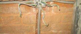
A couple of cables were pulled into the apartment, and from them, separate small branches were created in the installation boxes to sockets and lighting. This is again economical from a financial point of view, since less materials will be needed. But from a practical point of view, this will not work as well as we would like.
Each branch made had twists, which made the system very vulnerable. And in order to fix something in one room, it was necessary to turn off the power to the entire apartment. And if the cable in the wall broke or burned out, it was comparable to a disaster, so it was extremely difficult to repair.
And all this can be avoided if you make zoned wiring. The principle of its creation is simple: separate lines with suitable sections are laid off from the apartment panel, which correspond to the load in each individual room. For example, you usually need more sockets in the kitchen than in the bedroom, which means the load here will be greater and the type of sockets will be different.
*(This diagram clearly shows how each room receives its own line from the common panel, that is, the principle of zoned wiring)
Of course, this wiring method will require more cables, but, again, wiring is done once and for a long time, so it’s definitely not worth saving on convenience, which is closely related to safety here. Moreover, repairs and modernization will be much easier.
Planning your home electrical system
Regardless of the reasons for the decision to change the electrical network, the first step of this process will always be the same - drawing up a diagram. This is easy to do yourself, the main thing is to follow the steps described here:
- Prepare an apartment plan. Here you can make a copy of the technical passport, but in general it is usually not so difficult to sketch an approximate layout of the rooms. True, it is best, of course, to maintain the scale, and not to apply it by eye. By the way, the drawing can also be made on a computer using special engineering programs (for example, CAD). It is also worth noting that it is better not just to draw a diagram, but also to enter the exact dimensions of the walls - this will make it easier to calculate the amount of cable.
- After the wiring diagram has been drawn up - it’s better to make several copies at once, because it won’t be possible to do everything at once as a “finish copy” - we move on to the furniture. You need to take into account what is already worth and what you plan to buy. The same applies to electronics. It’s also worth considering what might appear in the near future. For example, growing children will need computers, consoles, a dishwasher or more household appliances may appear in the kitchen, etc.
*(This is only a small part of the electronics that everyone needs today)
- Once you have made a list of items that will require sockets, you will need to place those items in the appropriate locations. Of course, not every thing needs its own outlet, but in the kitchen, for example, it’s worth providing more of them - in case of a large dinner or cooking with 4 hands, for example. So items that need to be constantly connected and those that will be installed as needed should be separated. And don't rely on extension cords. It’s better to add another outlet to survive without such devices for as long as possible.
- After the primary circuit is assembled, sockets are drawn. Here it is necessary to take into account that they should not hide behind large furniture and it is advisable to be located where they will never be crowded with anything. The sockets do not have to be placed separately from each other; you can make points with several sockets and switches, if this is convenient.
- Transfer the sockets to a clean circuit and check if everything is ok.
- In order for an electrician to understand the circuit, it is advisable to use a table of special symbols and immediately note where, for example, there will be switches with one or two keys, open and closed sockets, blocks with sockets and switches, etc. But this is not necessary, since Usually an electrical specialist himself can distribute everything and clarify the details. If the wiring is done by the owners of the apartment, any designations for the types of sockets can be used.
*(This diagram shows well how to draw a floor plan of an apartment in order to then draw a wiring diagram)
- Now the lighting. Here you can give free rein to your imagination and make the scheme the way you always wanted - with a single source in the center of the room, zoning using several light sources, or simply placing everything randomly.
- When the light sources are placed, the switches are adjusted to them. It is necessary to provide for both the placement location (for left-handed or right-handed people), the quantity, as well as the height. Typically, switches are placed inside rooms, but this is not necessary - in bathtubs and toilets, for example, there are no switches and sockets due to humidity.
Now you have a clean diagram with all the sockets, light sources and switches for them, which means you can move on to planning the laying of the wire route. This is discussed in more detail in the next section.
Route planning
The points where power is supplied have already been designated; all that remains is to lay out the paths along which the energy will reach them. But before this, it is immediately determined whether the network will be open or closed.
You need to start with the installation box, which should be different in each room. Usually the box is located inside the room, however, in the case of a bathroom, it is recommended to leave it outside to avoid the contact connections being affected by high levels of humidity.
Installation boxes should also appear on the apartment plan; it is advisable to mark them with a special symbol so as not to lose them.
*(The junction box looks like this and is marked on the diagram with a circle with a cross)
Wires from sockets must extend to distribution points strictly parallel to the walls or floor. And the best solution is to connect your own cables to all outlets, rather than connecting them in series. Otherwise, the farthest one will be constantly at low voltage.
It is also worth mentioning situations when sockets in different rooms are on the same level or, technically speaking, on the same axis. Such sockets can be connected with wires that come from one box and one groove at a time. You can even use the same cable for them to save even more on material. But the cross-section of the wire must necessarily correspond to the amount of potential load.
It is better to highlight the wires that connect the sockets to the wiring box in one color, and those connecting the switches and light sources to the same box - in another.
And it would be possible to limit ourselves to one cable, which will power both lamps and sockets, but it is better to make two streams.
The next step is to lay the cables from the power distribution board to the junction boxes. It is also better to mark this with a new color.
Now you will need a fourth color in order to mark the cables that are supposed to be stretched to the location of devices that consume higher power current. These lines must have their own:
Grooves, that is, paths on the surface of the walls.
- RCD.
- Automatic machines.
But they shouldn’t have separate branches. And reinforced sockets are installed for such lines.
Among the appliances that may need such a system resistant to high voltage are ovens and boilers, which create a heavy load.
On the diagram it remains to indicate only one more line, stretching from the shield in the entrance. After this, the plan according to which the wiring will be created is considered complete. From it you can calculate the amount of material, and also use it as a direct plan when transferring the drawing to real walls.
*(The last drawn line is green, going outside the apartment into the entrance)
But before this you need to purchase wires, and for this you will need to determine their length and cross-section.
How to calculate cable length?
Using the diagram, you can make approximate calculations of the amount of cable if the exact dimensions of the rooms are taken into account. But they should be clarified and double-checked by transferring the diagram from paper to the walls. And this procedure is also carried out by professionals to determine as accurately as possible the placement of all sockets and switches, as well as the cables connecting them.
There are no clear standards at what height from the floor and at what distance from the corners the wires should run. Until recently, in Eastern Europe it was customary to install sockets at the level of the lowered arm, and switches at eye level, but it is now difficult to say where such standards came from.
Today, construction manuals typically provide the following information:
- Sockets are installed 30–35 centimeters from the floor (or 40–45 cm from the interfloor ceiling). Although they can be installed directly on baseboards, then the sockets must be special.
- The switches are at a height of about 90 cm, so that they can be used with their hands down and are also convenient for children.
It is important to note that these are standards for living rooms. For the kitchen, for example, they are different. Most of these rooms are occupied by countertops and cabinets, so sockets will need to be placed somewhere between them or even inside - hidden socket blocks in the form of a book or a “column” that rises when you press the lid are popular today.
*(This is not yet the most complex option for distributing sockets and switches in the kitchen)
There are also rules for bathtubs, in which sockets and switches are not placed at all, and everything is taken out of bounds. And if they are placed, then they are special, resistant to constant humidity and temperature changes.
For other rooms, the rules for laying the wiring are simple - the line should go straight down from the socket or switch (or up if the network is located under the ceiling). No ladders, corners or diagonal placements are allowed due to the danger of forgetting the location and then running into cables if you need to make a hole in the wall.
And to understand what wiring placement standards are in effect now, it’s worth studying this table and the picture below.
| An object | Distance from object |
| Windows and doors | Not less than 10 cm |
| Heating pipe | Not less than 30 cm |
| Pipes with flammable substances (gas) | At least 40 cm |
| Ceiling | From 15 cm |
| Stretch ceiling | From 10 cm |
| Corner of the room | From 10 cm |
| Floor | At least 15-20 cm |
*(A visual demonstration of the usual distances from various objects to power lines)
Why determine the cross section?
First of all, if the wire is of too small a cross-section, it will not be able to withstand a large consumption load. It will heat up frequently, resulting in:
- Deterioration of insulation.
- Damage to contacts on terminals.
This increases the risk of a short circuit significantly.
Also, not many people know that wires that differ in their cross-section also differ in prices. Therefore, it is worth doing the calculation in order not to overpay for material with excessive parameters.
*(Here is only a part of the existing wire sections, so choosing at random will be difficult)
It is important not to forget that the wires also differ in purpose, but this is easy to figure out if you know the correct color layout. It is suggested in the table below.
| Wire color | Purpose |
| Striped, yellow-green | Neutral protective conductor (grounding) |
| Blue | Zero working conductor |
| Black, red, brown, and all other colors different from the previous ones. | Phase conductors |
How to make calculations?
All the lines that appear on the apartment diagram come out of the access panel that distributes energy. And each of the designated lines inside has two devices:
- Automatic with suitable power.
- RCD.
In addition to this, there is always a common machine and a common RCD. The operation of this equipment depends on the total load on the network section limited to one room. It can be calculated by having in hand a list of all household appliances and other devices that will be used in the apartment.
*(This is how the described connection diagram for RCDs and automatic machines looks clear)
Usually the calculation occurs according to a very simple algorithm:
- The average power consumption is taken from the passport of each device.
- All these values are added up, as if assuming that all devices will be connected to the network at the same time.
This will give you the total maximum power. And if there are no passports for some equipment, then this is not a problem - you can use the average power of other similar devices or look for the necessary data in average power tables, like the one proposed below.
| electrical appliance | Average power |
| Warm floor | 1kW |
| Split system | 2.5 kW |
| Lighting | From 100 to 1000 W |
| TV | 150-200 W |
| Iron | 1 kW |
| Chargers for gadgets | 25-50 W |
| Washing machine | From 1.5 to 3 kW |
| Water heater | From 2.5 to 7 kW |
| Dishwasher | 2-3 kW |
| Laptop | 80 W |
| Microwave | 1.5-2 kW |
| Printer | 350 W |
| Desktop computer | 250-750 W |
But that is not all. Now you need to calculate the load current on the circuit section. To do this, you will again need a diagram where the equipment is distributed among the rooms.
For example, you need to make a calculation for a children's room in which they will constantly work:
- TV – 150 W.
- Warm floor – 1 kW.
- Night light – 100 W.
The total power per room is calculated using the formula:
I sum = P sum/U, where I sum is the total current in the room, P sum is the power of all electrical appliances when connected at the same time, and U is the usual voltage in the network, that is, 220 V.
*(Wire cross-section table)
Then in the designated nursery Isum will be equal to 5.7 A. And given that the network is not too loaded and does not have many branches, additional calculations are not required here. Just in case, another 5 A is added to the resulting number, and then everything is rounded up. This will give you 11 A for the nursery.
All that remains is to take the table proposed above and find a suitable cross-section of the copper cable. In the example, the load turned out to be ideally suited for a cross-section of 0.5 mm and one single-core wire is enough.
It is worth noting that special sockets are often purchased for children's rooms, the protection on which will not allow inquisitive minds to conduct their first lesson in learning about electricity. And if there are often small children in the house, then such sockets can be installed wherever young naturalists can reach them.
*(It is recommended to place sockets of this type in children's rooms)
OPEN ELECTRICAL WIRING
With open wiring, cables and wires are laid along wall surfaces, ceilings and other building elements of the building.
There are several installation methods:
- free suspension;
- directly on the wall surface or ceiling;
- in electrical baseboards;
- on strings;
- in platbands;
- on cables;
- in trays;
- on rollerskates;
- in a flexible metal sleeve;
- on insulators;
- in boxes;
- in the pipes.
In turn, open wiring is divided into three more subtypes:
Stationary.
This is wiring that is permanently connected and cannot be disconnected without the use of a special tool.
Portable.
The contacts of such wiring are connected to each other using plug connectors (not twisted or soldered), that is, such wiring can be disconnected at any time.
Mobile.
Used to connect mobile mechanisms to the electrical network.
The advantages of open wiring are as follows:
1. It is easy to install. Not even the most experienced electrician, but an ordinary man who understands electricity, can do such electrical wiring in an apartment with his own hands.
2. No additional equipment is required (such as a power tool for cutting grooves).
3. The integrity of ceilings and walls is minimally damaged during installation.
4. The wiring is available at any time for inspection or repair of damage.
5. It is mobile; if you need to move a switch or socket to another location, this can be done without any problems.
Disadvantages of open wiring:
1. It is unattractive and does not always fit into the interior.
2. During installation, it is necessary to take into account the technical standards and requirements of the premises (it cannot be used everywhere).
3. The open installation method is the most dangerous in terms of fires. If the load exceeds the permissible limit, overheating of the wiring and a fire is possible, which will immediately spread to the wallpaper or decor.
Methods for installing wiring in an apartment
It is important to immediately make a reservation that the following options will only be relevant for buildings with walls made of concrete or brick. They are not suitable for wooden houses, so the methods are not universal.
The first method will be relevant for those houses where there is not even a layer of plaster on the walls. Then the wiring can be placed directly on the surface of the walls. There are also two methods here, which were already mentioned earlier:
- Place the cables in corrugated plastic pipes if the thickness of the finish allows.
- Simply lay the cables open if they have double or triple insulation.
The second method is encountered most often, because it is suitable for cases when:
- The plaster has already been applied.
- Its layer will not cover the wires and you will have to make grooves directly in the wall.
This is a more difficult and longer path, but most often it turns out to be the only suitable one. In addition to the fact that the grooves have to be made, the wires in them will also need to be carefully fixed - with plaster patches or plastic staples.
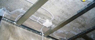
*(Dowel staples are especially suitable for ceiling wiring)
To make all the grooves correctly, it is better to make markings according to the diagram directly on the wall, then there will definitely not be any difficulties and there will be a chance to check everything again and correct something.
Now you need to determine how to lay the cables themselves. The lines from the distribution board to each junction box can be laid using the methods described in this table.
| Highway location | Peculiarities |
| Along the upper edge of the wall in a groove or corrugated pipe | Most often used |
| Over the floors until the floor screeds are poured (in plastic pipes) | This is the shortest way. Here, by the way, grooves are not useful either, since when the floor is filled, all the wires will be hidden. For such wiring, sockets built into baseboards are usually needed. By the way, now you can purchase special kits - a special plinth with cable channels, sockets, switches, junction boxes, etc. True, it is not suitable for any finish. |
| Along the ceiling | Here, most likely, you will have to make grooves, however, the consumption of materials will also be economical. Junction boxes can also be placed on the ceiling, but this will hardly be convenient when repairs are required. This method is only relevant when a suspended or suspended ceiling is intended to hide the lines. |
When installing the wiring yourself, only the first option is suitable, and despite the great advantages of the other two, it is no worse than them. It will just require more time, but since the plan to install the wiring with your own hands has reached the strobing stage, the hardest part is already over.
*(Grooves are the penultimate stage on the route of wiring)
Internal hidden electrical wiring
This type of electrical wiring is used in cases where it needs to be hidden so as not to disturb the design of the room - these are houses, apartments and other premises. Electrical wiring is hidden in wall grooves, under the floor, behind the frame of suspended ceilings. Wires under the floor, behind the suspended ceiling are pulled in a plastic flexible corrugation or in a metal pipe.
The method of laying wires depends on the design of buildings and the fire safety requirements of these structures. Grooves are made on concrete or brick walls where the wire is laid. The plaster is placed on top of the grooves. In this case, difficulties arise when repairing electrical wiring.
Hidden electrical wiring in a groove under the plaster
If the wires malfunction, the plaster is exposed, which leads to additional material costs. The electrical wiring diagram is assembled in junction boxes, usually under the ceiling. These boxes are mostly plastic, but can also be fireproof metal for installation in wooden structures.
Sometimes pipes up to 4 cm in diameter are laid in panel slabs for laying wires. For hidden wiring, the cable cross-section is larger than for open installation, since cooling is difficult with hidden wiring. Despite all these disadvantages, this type of electrical wiring is the most popular.
Did the article help you?