Each house or apartment requires a connection to the power supply, which is carried out through the installation of distribution boxes. For the purpose of safety and electricity metering, various modules are installed in the panels - control devices, automatic devices and other protective shutdown devices. There are many different options for how you can connect a circuit breaker to an electrical panel circuit.
How to connect a machine in a panel without errors
Modern electrical distribution panels are equipped with various metering and protection modules. These are protective shutdown systems, various relays, circuit breakers and multifunctional machines. Often they are connected incorrectly, as a result of which the functionality of the entire device is disrupted.
During maintenance of switchboards, violations of the installation of third-party modules were repeatedly observed, leading to instability of the system. Connecting automatic devices does not require special knowledge, especially since many are equipped with instructions or a connection diagram. Theoretically, electricians know how to correctly connect a machine in an electrical panel, but in practice, due to inattention or haste, they often make mistakes.
Selection of RCDs and automatic devices
The circuit breaker provides short-circuit protection, but it is not capable of detecting leakage current that may flow into the electrical equipment frame when the insulation coating is broken or through the human body. For these purposes, a residual current device (RCD) or differential circuit breaker is connected to the panel.
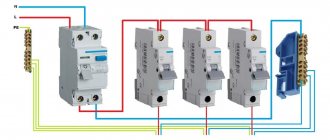
These devices are switching devices that constantly monitor the differential current of the electrical wiring, and if it deviates from the permissible value, a shutdown is performed. The principle of operation is clearly illustrated in the picture.
How does an RCD work?
The main purpose of these devices is to provide adequate protection in the event that a person becomes energized and to prevent fire that may be caused by a leak.
Main characteristics of the devices:
- rated current parameters (they must correspond to the circuit breaker or a higher value is allowed);
- operating voltage (220V or 380V, respectively, for single-phase and three-phase devices);
- The permissible leakage current parameter for household devices is considered safe 30mA.
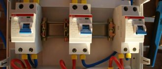
In our circuit, it is necessary to install a 16A RCD with a permissible leakage current of 30mA (elements C – F). These differential protection devices do not need to be installed for hallway and kitchen lighting.
RCD for 16A
Connecting machines in the panel with an entrance from above or below
Before connecting the machine from above or below, it is recommended to inspect the connecting sockets. Automatic shutdown modules have one or more pairs of connecting contacts. Some are fixed, others are mobile, which often leads to confusion. According to paragraph 3.1.6 of the rules for installing electrical equipment, when switched on one side, the circuit must be connected to the distribution box to the fixed contacts.
This condition applies to both the connection of machines and third-party protection modules. There are sometimes exceptions depending on the brand, date of manufacture and other technical factors. In order to correctly mount the machine in the shield with your own hands, you need to figure out where the moving and fixed contacts are located.
Using the example of AB series BA47-29, manufactured by Iek, you can make sure that the upper contact is fixed, respectively, the lower one will be movable. This is determined by the markings on the toggle switch itself. Many manufacturers have identical terminal arrangements. A symbol is installed on them, confirming the purpose and location of the connecting terminals. Similar manufacturers are Schneider Electric and Hager.
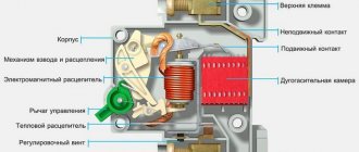
RCD devices are designed to prevent short circuits or circuit overloads. If there is a threat of power surges, a special disconnector located inside the unit is triggered. Its action is based on thermal or electromagnetic induction. It does not matter which terminal the phase is connected to. Therefore, turning on the machine from above or below does not make a significant difference, and in both cases it will turn off.
Selecting an electromechanical device
Taking into account the load parameters and cable characteristics, you can select a device for installation in an electrical panel. All necessary information about the electromechanical device is located on its front panel.
The ability to decipher the switch markings will help you make the right choice.
The first line usually indicates the brand of the product. It’s better not to save money, but to choose an automatic device from a well-known manufacturer: Legrand, IEK, ABB, Schneider, Electric, Hager (+)
Voltage, frequency and rated current
In the next line you can find information about two important characteristics - voltage and frequency. The most common “format” is 220/400V 50Hz. This means that you can connect one or three phases at a frequency of 50Hz.
If we take all design types, then the correspondence of poles and voltage will be as follows:
- 1-pole – 220 V, (1 wire – phase);
- 2-pole – 220 V (2 wires – phase/neutral);
- 3-pole – 380 V (3 wires – phases);
- 4-pole – 380 V (3 phases/1 zero).
The rated current value limits the use of certain types of cables - and be sure to take this into account when choosing automation. Therefore, when buying a switch for an electrical panel, check what types of wires are involved in constructing the overall circuit.
The preliminary calculation of the circuit breaker rating is based on data on the total power of consumers, the presence of starting current of some electrical appliances, current strength and the estimated demand coefficient.
Under no circumstances should you rely on the maximum voltage in the network, otherwise the following may happen.
Let's assume that buying new household appliances leads to overloading and constant knocking out of the machine. You will want to increase its power and replace it with a new one that has a higher current rating.
As a result, when several powerful devices are connected to the network, the machine will not work, but the wires will overheat, resulting in a short circuit (the insulation will melt and a fire will occur).
If the cable cross-section does not correspond to the load, it must be reduced (or, conversely, the communications must be updated). But you cannot select a circuit breaker based on the maximum load - only by cable (+)
The circuit must be built in such a way that the weakest link is the circuit breaker (not the wires), which is designed to protect against overload.
Is VTX important?
The letter designation of the time-current characteristic precedes the digital marking that determines the rated current.
To understand what the essence of technical characteristics is, let’s look at the formula:
k=l/ln , where
- l – current in the network;
- ln – rated current value;
- k – multiplicity.
The category depends on the multiplicity:
- B – 3
- C – 5
- D – 10
The correspondence graph is clearly shown in the figure:
Three zones, painted in different shades, indicate the categories of performance characteristics: red - category B, blue - category C, green - category D (+)
The operating speed of the machine depends entirely on the multiplicity: the larger it is, the faster the shutdown will occur. For domestic use, the listed categories are used, but in addition to them you can find circuit breakers with BTX categories G, K, L, Z.
Circuit breaker B16 at a current of 150 A operates instantly, while D16 only after heating the plate, after several minutes. The most common category C is used in everyday life and in production, in networks with medium and low starting currents. Category B refers to high-speed ones and is involved in old network schemes.
It should be taken into account that the response speed is also affected by the ambient temperature. The dependence is as follows: the higher the temperature, the less current is needed for the machine to respond.
When assembling electrical panels, experienced electricians take this compliance into account and try to leave a little free space inside the panel so that overheating does not occur due to the operation of a large number of devices.
Let’s not forget about the selectivity rule: of all the protective devices embedded in the circuit, the one that is closest to the point of overload should operate first. If the nearest machine did not respond, but the next one (let’s say the driveway one) worked, the device parameters were selected incorrectly.
Polarity, PKS and current limiting class
The number of poles of modern circuit breakers can vary from 1 to 4, with 1- and 2-pole devices serving single-phase circuits, and 3- and 4-pole devices serving three-phase circuits.
PKS is the maximum (nominal) switching (breaking) capacity. Its indicator indicates the value of the maximum short circuit current (TCC) at which the machine can still operate.
The parameters of the TKZ should not exceed the PKS, otherwise the guarantee of protection will be removed. If an automatic device has provided protection against TKZ several times, its resource is most likely exhausted and requires replacement.
In everyday life, devices with a PKS of 4.5 kA are most often used, but there are modifications of 6 kA and 10 kA. The latter are relevant for industrial use (+)
And the last characteristic is the current limiting class. The label may indicate class 1, 2 or 3, in some cases this indicator is not present. If it is not there, the device belongs to class 1 current limitation. Each class denotes a certain speed of the machine’s reaction to the occurrence of a fault.
Quality and cost depend on the class, since the higher the indicator, the more expensive the device.
The duration of the machines is approximately as follows:
- 3rd grade – 3 ms;
- 2nd grade – 5 (6) ms;
- 1st class – about 10 ms.
Most modern switches belong to class 3.
Once you have selected the appropriate circuit breaker, you can begin installing or replacing it.
Each element is a module that occupies a number of spaces equal to the number of poles (in the figure there are single-pole samples, i.e. 1 space). The size of one “cell” is 1.75 cm, two – 3.5 cm, etc. Additional information on the selection of switches and the characteristics of different models is presented in this article.
Why is it not recommended to connect AV from below?
Some models from modern manufacturers allow circuit breakers in distribution boards to be connected to the lower terminals. They are equipped with special fixing rails or tires.
Such a connection to the machines in the panel will contradict the rules of the PUE, but does not prohibit connection to the lower contact. This rule works as a generally accepted procedure, thanks to which an experienced electrician understands that before servicing the electrical panel it is necessary to de-energize it. The first thing he will do is turn off the machine, assuming that the phase is on top. Consequently, after disconnection at the lower contacts and outgoing circuits, the voltage will turn off.
If we imagine a situation where the lower terminal is used to connect phase wires, by an electrician who did not consider it necessary to follow the connection rules according to the PUE. When it's time to replace the machine, another technician, out of habit, turns off the power to the top contact and tries to disconnect the machine by touching the bottom contacts with his bare hands. As a result, he receives an electric shock. That is why it is customary to comply with the rules established in the PUE.
Under the Union, all circuit breakers had one standard, which assumed the location of fixed terminals on top. Now, given the diversity and wide range of AVs from imported manufacturers, it is difficult to say where each contact is located. Some companies adhere to generally accepted rules, while others, on the contrary, try to diversify their products by introducing their own innovations.
At industrial enterprises, instead of conventional circuit breakers, switches are installed, the power of which is connected in accordance with all the rules of the Electrical Installation Regulations. If you do the opposite and turn the RB over, then its position will look unusual and even be uncomfortable. If you look with an experienced eye, you can immediately see the correct connection. If the switch is set correctly, then by turning it off, you can be sure that the lower contacts remain without voltage.
Work order:
Preparing to install the cabinet
Installation from scratch usually involves the presence of a niche in the wall that has already been prepared by the builders and all electrical cables and wires belonging to the apartment (household) circuit laid out in the area of this niche.
Such a “landscape” usually looks like a rectangular niche carved into the wall, where first of all you need to select a cabinet of appropriate (suitable) sizes.
The commercial market offers ready-made electrical panels in various shapes and sizes. In addition, recent years have introduced electrical cabinets made of plastic. An interesting design option for apartments made of self-extinguishing plastic
If there is no prepared place, you will have to make a niche with your own hands or use wall-mounted installation.
In the second case, the installation site is marked taking into account the overall dimensions of the electrical panel. In principle, these are standard construction works that do not present any special difficulties.
Cabinets for electrical panels are assembled from durable and strong materials, but relatively light.
As a rule, the following is used to make a box:
- thin-walled (1-1.5 mm) sheet metal;
- metal connecting corners;
- screws and nuts.
In most cases, a ready-made box is purchased, because the range on sale is huge, including plastic products. The classic design shape is a rectangle or square.
A more reliable design of the box for the shield, factory-made, made of thin-walled sheet metal. This design option is more reliable compared to plastic products
Outdated cabinet designs required installation inside the rear panel based on dielectric materials (hard rubber, textolite, etc.), where electrical equipment was mounted. In principle, such a scheme for everyday life can be used in modern conditions.
Internal filling of the electrical cabinet
Modern architecture is somewhat different. The cabinet is made entirely of metal, and inside, on the back wall, metal cross-beams (DIN rails) are also installed.
All technical equipment is “put on” these traverses:
- machine;
- RCD;
- switch;
- other electrical installation products.
According to modern standards, any of the above elements is designed for installation on a DIN rail. It is also useful to sign all devices installed on the rail, and additionally draw up a diagram with the signatures of all electricity consumers in the apartment/house.
Of course, you can deviate from these rules, given that installation on traverses simply provides ease of installation/removal of equipment. But then you should consider options for reliable fastening.
Almost all modern designs of electrical switchboards are equipped with special traverses (DIN rails), on which all switchboard equipment is installed without the use of screws
In addition to the DIN rails, one or two insulated plates with screw terminals are mounted inside, usually in the lower part - a busbar for neutral and grounding conductors. Additional buses can be used for contact groups of low-voltage equipment - relays, modems, etc.
It is recommended to make the electrical cabinet drawer as spacious as the size of the niche cut into the wall allows. The equipment should be placed inside rationally, in such a way that it is convenient to maintain and remove in case of replacement.
That is, the assembly of the box, again, must be preceded by a calculation of the required space for installing the assembly components. Any electrical cabinet must be equipped with a door and a lock.
Performing conductor insertion
The supplied power line, as well as conductors and cables taken directly from the apartment (house), must be led inside the assembled cabinet. Accordingly, a sufficient number of holes will be required on the top and bottom sides of the box.
The diameters of the holes must ensure free passage of cables (wires). In this case, each hole must be equipped with a protective insulating ring (rubber, plastic).
Special attention should be paid to the technique of introducing centralized power cables and cables leading into the apartment (house) circuit. The picture shows a gross violation when the cables are passed through the holes of the shield without protective insulating rings
At the cable inlet and outlet, as a rule, clamping clamps are installed, by means of which the conductor is securely fixed to the cabinet wall for internal installation and/or to the base plate (plate) on which the cabinet is fixed for external installation.
Also, a grounding bus interface is made on the side or bottom wall of the structure. A hole is drilled for a bolted connection or a ready-made one is used, if one is provided on the box body. A grounding bus is connected to this connection during the installation process.
Stripping the cable
Using a knife, remove the outer insulation from all cables inserted into the shield and mark the cores by groups. Bend the numbered wires and secure them to a homemade hook on the side of the shield.
Trying on distances
Before connecting the wires, first try on and estimate the places where the modular equipment will be located and how long the wires are needed to reach them.
Install the DIN rail, zero bus and ground bus. You don’t screw or secure anything, just try it on. Your task is to understand the general location of the machines and where the wires are laid. What you should pay special attention to:
- ⚡distance between rows of machines
- ⚡distance between machines and zero tires
Try to make these distances not too small, otherwise in the further installation process it will be extremely inconvenient to insert and connect the wires.
Grounding and grounding bars
After preliminary fitting, mount and secure the zero busbar and grounding busbar in the panel. Above the terminals of the busbars you sign the group numbers.
Since the grounding wires never burn out, the grounding bus can be mounted on top of the shield, without any extra wire. But it’s better to place the zero one at the bottom. In case of unforeseen circumstances, you will have a certain supply of wire and by moving the busbar higher, you will be able to disconnect all the equipment again without replacing or extending the conductors.
Select the neutral and grounding conductors from the bundle of cleaned wires (the neutral conductor is usually blue, the grounding conductor is yellow-green), strip them with an insulation stripper and connect them one by one to the busbars. There is no need to make any extra supplies or additional bends.
Assembly of modular equipment in an electrical panel
Mount and secure DIN rails. Previously laid protective conductors (neutral and grounding) must be behind the DIN rail. Sequentially click the machines onto the DIN rail according to your groups.
Follow this layout of modular equipment:
- ⚡introductory circuit breaker or load switch is installed first
- ⚡then comes the voltage relay (if you provided it in the circuit)
- ⚡further automatic devices of the most powerful consumers (hob, oven, split system) or RCD with differential automatic devices
- ⚡simple machines for sockets and switches are located in the bottom row
Try to install all automation in the center, leaving more space on the sides for laying conductors or for installing additional modular devices in the future. To ensure that modular equipment does not ride on the DIN rail, it is very convenient to use clamps.
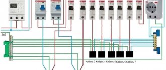
8.Connecting wires
Start wiring from the top row. From the bundle of phase outgoing conductors, select those groups that go to the top row and tie them into a bundle with cable ties.
Lay the bundle along the edges of the shield, form a comb at the end with the letter G and insert the stripped wires from the bottom of the machines. Then install the lower rows of machines and repeat all operations.
Comb shank
To sequentially connect machines located in the panel in one row, we use a comb busbar.
We cut it to the required length according to the number of machines in the rows and insert it into the upper terminals of the machines and tighten the screws. Please note that if you have budget machines without an additional contact specifically designed for a comb bus, then the bus must be inserted into the machine in such a way that the protruding part of the bus faces you.
Then you can easily insert a wire into the contact of the machine along with the busbar contact, and when tightening the machine it will not bend and the conductor will not come out of the contact.
Internal switchboard switching
For further disconnection of switching, use pieces of prepared wire PV3*10 (for connecting the very first machines in a row), PV3*1.5 (for zero contacts of the voltage relay) and PV3*2.5 for difavtomats and RCDs of individual groups.
If single-core wires are used, then bend the end of the wire entering the machine twice, thereby increasing the useful area of contact with the contact.
Well, for stranded ones, be sure to use sleeve tips.
Connection diagrams
The supply phase conductor of the cable is connected through an input device (RCD, circuit breaker, load switch), depending on your circuit.
The zero core goes directly to the zero busbar. If there is a separate RCD for the bathroom in the panel, run the conductor from the zero busbar to this RCD. Also, connect the voltage relay with a separate conductor from the zero bus. First connect the phase conductor from the input circuit breaker to the voltage relay and then from it power the upper contacts of the very first circuit breaker in the rows. The rest of the machines in the row are powered by it, thanks to the previously installed comb busbar.
All individual pieces of conductors for connection must be prepared in advance. To do this, measure their required length from the terminals of one equipment to the terminals of another. You strip the ends with an insulation stripper, and if you have a flexible wire, crimp them with NShVI lugs.
Inscriptions
After the final connection of the conductors, go through all the contacts again with a screwdriver and check their tightness. At the end, do not forget to label all switching devices on the panel.
At this point, the installation of the shield can be considered complete.
Is insulation coming into contact an error?
The most common mistake when installing a machine in an electrical panel is the presence of insulation that has gotten under the contact mount. It often happens that when installing circuit breakers or changing the box, after a while, the wiring inside it burns out. This happens when the ends of the wires are poorly stripped and particles of insulation get under the clamp, thereby worsening the tightness of the connection. In this regard, the insulating layer of the electrical wiring and insulation of the machine melts, which can cause a fire.
To avoid making such mistakes, it is necessary to thoroughly clean the ends of the wires connected to the automatic protection, and then make sure that there are no insulating particles left on the cleaned ends. After cleaning the insulation, form connections, tightening them well with a screw clamp.
Why can’t you connect several wires of different cross-sections to one terminal?
Sometimes there is a need to install several machines powered by one core, and for this it is advisable to use special rails or comb buses. However, they are rarely available, so you have to use ordinary jumpers - pieces of wires connecting the power to the AB.
This connection can be made in the shield with your own hands. To do this, you will need jumpers made of electrical wire with an identical cross-sectional area. To make a jumper, it is not necessary to cut, clean and connect each piece to each other. It is enough to measure the required length so that it is enough to combine all the AB contacts, and then, having given the required shape, strip the wire at the bends that are inserted into the terminals of the machines. Thus, a complete, continuous jumper emerges.
It is not recommended to connect machines using wires of different sections. When the ends are fixed in the terminals, the thick wires will be tightened well, and the wires of a smaller cross-section located nearby will be weakened. Subsequently, the sheath of wires and AB contacts will begin to melt at this point, which can cause a fire.
When installing an AB in an apartment or private house, use wiring with a cross-section of 2.5 mm2. This is determined by the load, the amount of energy expended, and also indicates how many amperes the machine should be set to.
What tools are needed?
To install a switchboard yourself in accordance with current regulations, it is no longer enough to arm yourself with a knife, wire cutters and a screwdriver. In order to correctly connect all the elements and connect consumers, you must use: an insulation stripper that allows you to quickly, efficiently and safely expose the ends of the wires, a manual clamp for crimping the tips, modern-style wire cutters, with which you can achieve a perfectly flat cut of PV-3 stranded copper wire.
Type of set “Electrician’s assembly knife”
Wiring cutters
Insulation stripper
Manual clamp for crimping lugs
In addition to the insulated screwdriver set, it is also recommended to use a cordless screwdriver to speed up the initial screw tightening process as much as possible. Installation of some models of household switchboards requires the use of a set of open-end wrenches/socket wrenches.
Set of rubber-coated electrician's screwdrivers
Set of socket and wrenches
Screwdriver for quick installation of control panels
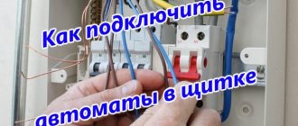
Installation
Before installing protective devices, it is necessary to determine in advance how many wires can be connected to the machine, how the supply wires will be connected, and only after that think about connecting the circuit breaker to the electrical circuit. If there is any doubt, it is better to refer to the basics of electrical installation. They describe in detail how to correctly connect circuit breakers in an electrical panel, prepare wires and carry out maintenance of electrical panels.
To install the machine in the electrical panel, you will need some tools and materials.:
- Cables of the same cross-section for the main circuit and jumpers when installing several circuit breakers.
- Insulating tape.
- Knife for removing insulation from ends.
- Screwdrivers of various types - Phillips or slotted.
- Devices for determining phase - indicator or multimeter.
- Pliers or regular wire cutters.
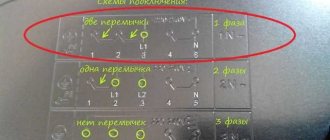
In order to understand what actions need to be performed in different situations, you need to consider different connection methods - single-pole and double-pole.
Single pole
For a single-pole connection, it is necessary to have a negative and power conductor. This method was used previously and was a unified standard, where the phase conductor was connected to the input contact AB, then passed through the output contact, went to the electric meter and was routed through the RCD. The neutral conductor is also powered by connecting through the meter.
Sometimes it is allowed to install the AV on the neutral conductor, although this contradicts the rules specified in the PUE, which says that the releases are installed when, when triggered, all conductors related to this circuit will be de-energized. Many people install two machines, one for plus, the other for minus. Therefore, it is worth considering whether it is necessary to set the machines to zero when there is a threat of equipment failure according to the description of the PUE.
Bipolar
With this connection of AV in single-phase networks, three types of conductor are used - grounding, power and neutral. The input contacts located on the top of the AB are marked with odd numbers, and the output with even numbers.
The supply wire is connected to input 1, after which it is tightly clamped into the terminal. The neutral, suitable for terminal 3, is connected in an identical way. Then the power core is passed through the meter and distributed evenly across all groups of switches. From pin 4, the yellow-green wire is connected to the ground bus by passing through the three-phase reading and protection blocks.
Features of connection diagrams
To connect houses to the electrical network, self-supporting insulated wires are usually used, extending from overhead power lines. Despite the advantageous characteristics of SIPs, it is not recommended to connect them and install machines directly. This is explained by the fact that during long-term operation the aluminum conductors begin to overheat. In this case, the insulating layer melts, leading to fire or malfunction of the AV.
To avoid such cases, use special adapters connecting copper and aluminum wires. This circuit for connecting the machines will secure further maintenance of the electrical panel and increase the operational period of the RCD.
Based on the above, we can say that the installation of machines is not particularly difficult, so it can be done independently. The main thing is not to forget the basic rules for connecting AV: use conductors of the same cross-section, do not place the machine on the neutral conductor and make the connection in accordance with the PUE. It is also worth considering common mistakes and observing safety precautions when working with electric current.
Checking the operation of the control panel
It is done by massively (sequentially) turning on all possible consumers, after which it is necessary to walk around the entire facility, checking each outlet using some known working portable electrical appliance. If the automation does not turn off the power to the line at any stage, it means that the installation was carried out correctly.
Then you need to observe the control panel in full load mode for some time. If there is sparking, smoke, a crackling sound is heard, or a burning smell is felt, this indicates unreliable contact in one of the connections, causing overheating, or a malfunction of the automation device that needs to be replaced.
In the absence of the above phenomena, it is recommended to check the functionality of the main components that ensure the safe operation of the internal electrical system - the RCD. For this, a special tester is used that creates leaks of a standardized value (10, 30, 300 mA). The price of this device is quite affordable even for a private master. Some models are equipped with their own control button, which, when pressed, should instantly turn off the device.