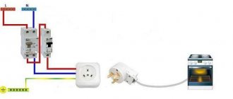
Why do you need a surge protector: a brief explanation
The very name of this electronic circuit explains its purpose. The word “filter” indicates the elimination of harmful interference, and “network” identifies its source.
In other words, all electrical debris coming from the power supply is screened out at the input of our device and does not affect the quality of operation of the household appliance. The main network signal of 220 volts with a frequency of 50 hertz passes through the filter without hindrance.
Electromagnetic interference in the network appears spontaneously; it is impossible to predict its occurrence. Even simply turning on an incandescent lamp generates an initial surge of current, creating a zone of transient processes.
Connecting the electric motors of a refrigerator, washing machine or dishwasher is associated with a change in inductive reactance. The current of such switching on can exceed tens or more times the rated load value.
This creates a significant voltage drop in the network. And then there follows a surge, forming high-voltage interference.
These processes take place for a short time. At the time of using analog household appliances, they did not cause much harm, and simple filters were built into audio and video equipment that performed their functions perfectly.
They reliably smoothed out all those quick dips and spikes in voltage by their design, preventing them from reaching sensitive electronic circuitry.
It is important to understand that the filter works exclusively with short-term dips and peaks in the input signal. If such a process takes a little longer, then another device is needed - a voltage stabilizer.
What harm does electromagnetic interference cause?
- The voltage of short-term pulses is superimposed on the main power signal of the network 220. In this case, an overvoltage may occur at the amplitude point, which can burn through the working insulation layer or damage the electronic component.
- Extraneous signals penetrating into low-current circuits distort the operation of sound recording or sound reproducing devices, video equipment, television receivers, and expensive digital equipment.
- Special equipment allows you to gain access to confidential information through electromagnetic noise transmitted along a neutral conductor laid outside the apartment.
To reliably deal with interference, you need to know the features of your home network.
Basic performance characteristics of filters that are important to know
The fight against electromagnetic interference from the network is carried out in different ways. Screen adaptation and the use of electronic components are popular.
Which case combats interference more effectively?
A distinctive feature of high-quality products is a closed metal screen, which eliminates the passage and interference of extraneous electromagnetic signals. It is connected to the ground loop.
In Soviet times, it indicated the diagram of internal connections and technical characteristics of the product.
Such a housing can be made common to the entire device, as is done for a microwave oven or a computer system unit.
Numerous modern modules produced to filter interference from household networks have a conventional plastic casing.
They are deprived of the ability to protect against external interference and extraneous radiation.
In addition, marketers often call ordinary extension cords a surge protector, which is not entirely correct. In this case, their external similarity is used.
Design features and electrical characteristics that improve filtration conditions
Availability of a switch
Marketers pay attention to it by showing small ease of use. It is installed on regular extension cords.
However, this is where his role ends. It simply allows you to turn off or supply power to consumers without pulling the plug from the socket. This function is useful when the socket block is covered by furniture and access to it is difficult.
Permissible load current
I recommend paying close attention to the electrical characteristics declared by the manufacturer. They must be observed.
The load current, for example 10 amperes shown on the case, is the maximum consumption of all connected devices. It cannot be exceeded, because the internal circuit will overheat and insulation damage will occur.
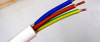
It is important to take into account here that in such a closed structure the thickness of the stranded copper wire does not exceed 1 mm square.
The chokes are made with the same cross-section and act as inductive reactance.
When connecting consumers to filter sockets, it is necessary to calculate the total load current. Quite often a situation arises where it is unacceptable to turn on a vacuum cleaner or kettle in parallel with a running computer.
Filters manufactured in countries with a voltage of 100 or 110 volts (for example, the USA, Japan) may fall into the hands of individual users. They have different pin connectors.
But replacing them with our standard will not allow the use of such devices in our wiring. The entire internal circuit needs to be redone, and this is more expensive than purchasing a new unit.
Main electronic components of the internal circuit
Varistor protection
Even the cheapest designs use one varistor. It stands at the input between the phase and zero potentials. At normal network voltage, it has a very high electrical resistance and does not interfere with the operation of the circuit.
When a residual overvoltage pulse comes from the network, not completely extinguished by the SPD devices, the internal resistance of the varistor sharply decreases.
Due to this, according to Ohm’s law, a large current begins to flow through it, which is converted into thermal energy, and only the permissible voltage level enters the circuit.
Three varistors are used for three-wire wiring. They are turned on to eliminate differential and common-mode voltage noise.
Inductors and capacitors in a high-frequency circuit
The design of the high-frequency filter uses the dependence of capacitive and inductive reactance on the signal frequency.
The usual 50 hertz easily passes through the inductance. For high-frequency interference, a large resistance is created here. Therefore, the windings of the coils are connected in series with the conductors. They are made with the same cross-section as the main wire.
Capacitors are connected in parallel to differential and common-mode noise. Capacitance has an inverse relationship with signal frequency. It shunts high-frequency voltage.
Features of the ferrite ring
It is useful to place a ferrite filter at the ends of the cable a few centimeters from the connector, as is done on a laptop power supply.
Such a passive element in the form of a solid or composite cylinder suppresses RF interference passing through the cable with its inductive reactance.
In this case, depending on the composition of the material and the brand of the ferrite ring, the following occurs:
- reflection of part of the high-frequency interference by inductance back into the network;
- or partial absorption of high-frequency waves by ferrite material (more efficient);
- or a combination of both functions.
The quality of interference suppression by ferrite can be increased. It is enough to pass the cable several times around its ring. However, this is not always possible in practice.
It should be taken into account that interference-absorbing ferrites are not used on multi-core wires of low-current digital data transmission circuits or audio and video signals. They work as an in-phase transformer passing similar signals.
Schematic diagram
Figure 2 shows a typical power supply network filter circuit. It shows a three-wire (European) power supply network: “phase” - “zero” (“neutral”) - “ground”. Immediately at the filter input there is a varistor VR1.
Its task is to suppress high-voltage surges in the network. When such a surge appears, the electrical resistance of the varistor drops sharply, and it closes this interference through itself, not allowing it to pass further. Next, inductor T1 and capacitors C1, C2, C3 are included, forming an LC filter.
The resistance of the inductor increases with increasing frequency of the current, and the resistance of the capacitors decreases, so that all high-frequency noise is delayed or “drains” into the ground.
Interference can occur not only between the network wires (“phase” and “neutral”), they will be filtered by capacitor C3, but also between the “phase” and “ground”, and interference “neutral” - “ground” is also possible. To effectively suppress such interference, capacitors C1 and C2 are used.
Rice. 2. Typical power supply network filter circuit.
In the absence of ground, the common point of capacitors C1 and C2 “hangs” in the air, which leads to the creation by them and inductor T1 of a parasitic oscillatory circuit, which begins to emit a high-frequency electromagnetic field, becoming a source of potential danger for nearby radio equipment.
Rice. 3. Network filter circuit without grounded capacitors and connection to ground.
Therefore, in a two-wire network, filters are used without these capacitors and connection to the ground (Fig. 3). A typical amplitude-frequency response (AFC) of a network filter is shown in Fig. 4. From this graph it is clear that the higher the frequency of interference, the more effectively it is suppressed.
Rice. 4. Dependency graph.
It is worth dwelling on one feature of power filters. It will all be about the same “land”. There is a whole class of network filters in which the grounding wire has no connection with the internal circuit, except for the corresponding contacts of the Euro sockets themselves and the grounding contact of the Euro plug.
This achieves an important advantage: when operating from a grounded network, all filter sockets are grounded, as expected. But if there is no “ground” in the power outlet (a typical case of a domestic power supply network), all filter outlets are connected to each other via a grounding contact (of course, the filter itself is not grounded)
Why is it important?
Let's imagine, for example, a diagram of connecting various peripherals to a computer, shown in Fig. 5a (typical case - a printer, scanner, external audio amplifier, etc. are connected).
This is an ideal scheme: everything is connected to a grounded power supply network, the potentials of the device housings are the same (zero), since they are connected to ground. In the event of a breakdown or damage to the insulation of any of the devices, the “excess” voltage will go into the ground.
Rice. 5. Schemes for connecting various peripherals to a computer.
Now let's take a connection diagram for the case of a network without grounding (Fig. 5b). As you can see, there is no ground wire, and the only connection between the device cases is a low-current interface cable (more precisely, its braided shielding).
If there is a difference in potential between the computer case and the external device (and this happens all the time!), equalizing currents flowing from a higher potential to a lower one can easily “burn out” the input and output ports of the connected devices.
There are many such cases. The most common is the burnout of the input or output of the sound card if it is connected to an external signal source or to a sound amplifier.
To solve the problem, you need to connect these devices to a “European” extension cord, not even connected (for lack of it) to an external “ground” (Fig. 5c). Here, the electrical potentials of all devices are equalized, through currents will choose an easier path through the grounding contacts of Euro sockets, and nothing bad will happen.
Industrial and homemade filters for a three-wire power system
Among the mass-produced products there are quite useful technical solutions that the home craftsman should pay attention to.
Brief overview of useful functions of factory models
One of the popular developments, widely represented in the trade, is the Pilot series of filters of different designs.
The circuit diagram of the Pilot surge protector is shown in the picture to make it easier to understand its capabilities.
I will dwell on the tasks that Pilot XPro, specially created for comfortable work, extending the life of connected consumers and reducing electricity consumption, is designed to solve. This:
- protection against surge voltages by varistors;
- prevention of high-frequency interference by inductive-capacitive reactances;
- power management through the introduction of the Master Control ;
- protection against overvoltage associated with zero loss;
- smooth switching off and switching on of equipment under load with the Zero Start due to the elimination of current surges by the built-in circuit ;
- automatic switching on of consumers after elimination of emergency power failure;
- two levels of protection against current overloads or short circuits due to a fuse and a bimetallic release;
- indication of network connection and supply voltage level;
- temperature control and automatic shutdown when overheating.
Master Control function defines one socket as the main socket (as a master socket). The main consumer with a power of more than 50 watts is connected to it, for example, a computer system unit.
When it is turned on, the automation simultaneously powers three other sockets with peripheral equipment. It also turns them off when power is removed from the main unit.
There are sockets on the case that are not controlled by microprocessor automation. They are used for lighting, telephones, and other equipment.
You can find out more detailed information about this equipment in a short video by the owner of ZIS Company.
Description of the operating principle
A standard surge protector passes electrical current through a cable from the outlet to a number of electrical and electronic devices connected to the device. If the voltage from the outlet rises above the permissible level, the uninterruptible power supply device diverts additional electricity from the outlet to the ground wire.
The most common type of surge protector has a component called a metal oxide varistor, or MOV, that removes the extra voltage. The MOV forms the connection between the phase power line and the ground line.
The varistor itself consists of three parts: an oxide-metal part in the middle of the cable connecting to the power supply and grounding lines, which are made of two semiconductors. These semiconductor devices have variable resistance that varies with voltage. When the voltage is below a certain level, the electrons in the flux semiconductors combine in such a way as to create a very high resistance. If the voltage exceeds this level, the electrons behave differently, creating lower resistance. If the voltage matches the specified resolution, the varistor does nothing.
Photo - Main line filter
As soon as the additional current is diverted to the filter and to ground, the phase line voltage returns to normal levels. Thus, the surge protector Pilot (Pilot), Defender, and others only remove the pulse current, while allowing other devices connected to the conductor to continue operating at a normal rhythm. In other words, network noise suppressors operate like a pressure-sensitive valve that only opens when too much pressure is applied.
Photo – Professional filter circuit