A little theory
An LED requires a constant voltage or current to operate properly. They should be:
- Constant in direction. That is, the current in the LED circuit when voltage is applied must flow from the “+” of the voltage source to its “–”.
- Stable, i.e. constant in value, during the operating time of the diode.
- Not pulsating - after rectification and stabilization, the values of constant voltage or current should not change periodically.
Diagram of the voltage waveform at the output of a full-wave rectifier when filtered by an electrolytic capacitor (in the diagram there are black and white rectangles marked “+”). The dotted line is the voltage at the rectifier output. The capacitor is charged to a half-wave amplitude and gradually discharged across the load resistance. “Steps” are pulsations. The ratio of the step and half-wave amplitudes as a percentage is the ripple factor.
For LEDs, the available voltage sources were initially used - 5, 9, 12 V. And the operating voltage of the pn junction is from 1.9-2.4 to 3.7-4.4 V. Therefore, turning on the diode directly is almost always its physical combustion from overheating with high current. The current must be limited by a current-limiting resistor, wasting energy on heating it.
LEDs can be switched on in series, several at a time. Then, by assembling a chain of them, the sum of their direct voltages can be used to almost reach the voltage of the power source. And “pay off” the remaining difference by dissipating it in the form of heat on a resistor.
When there are dozens of diodes, they are connected in series circuits that are connected in parallel.
LED garland
Figure 9 shows a garland of eight LEDs. The nominal drop voltage on each is about 2V. Resistor R1 limits the current.
And the garland can be powered from a voltage source of 20-25V. For the garland to blink, it is enough for one of the LEDs to be blinking. HL1 interrupts the current in the circuit while blinking, so the other seven LEDs blink at the same time.
Rice. 9. Scheme of a homemade garland of eight LEDs.
Figure 10 shows a garland consisting of an almost unlimited number of LEDs. Here the LEDs are connected in parallel (through current-limiting resistors). This means that each of them lives his own life and does not affect the work of the others.
Here you can use a variety of LEDs - different colors, flashing and non-blinking. At the same time, the non-flashing ones will light up steadily, and the blinking ones will blink.
You can put two or three-color flashing ones - they will shimmer in different colors. In general, the garland will all sparkle, shimmer... very beautiful. And the more diverse the LEDs, the more beautiful.
Rice. 10. Diagram of a garland consisting of an almost unlimited number of LEDs.
However, the power of the power source must also be taken into account. If with resistors with a resistance of 510 Ohms and a power supply voltage of 12V (or from 6 to 18V), the current through each LED will be somewhere around 0.02A.
That is, if there are ten LEDs, then the current is 0.2A, and if this garland is made of one hundred LEDs, then the current, accordingly, will be as much as 2 A. Therefore, choose a source that is capable of delivering the required current. For example, the network adapter from a laptop provides 3A, but the power supply of the Dandy game console only provides 0.3 A (300 mA).
So the Dandy unit can only power 15 LEDs. However, the resistance of the resistors can be increased. Then the current will decrease (according to Ohm’s law), but the brightness of the LEDs will also decrease.
But the number of LEDs can be increased without increasing the current. Figure 11 shows a garland similar to the one in Figure 10. But in it the LEDs are connected three in series.
Such a garland can be powered by a voltage of 9-18V, consuming a current of only about 0.02A for each three LEDs. Thus, the number of LEDs is tripled, with the same current consumption. At the same time, for a trio of LEDs to blink, it is enough to have one blinking LED in it.
Rice. 11. Diagram of an LED garland, in which the LEDs are connected three in series.
Each branch (Fig. 11) can have more or less than three LEDs. It is important that the total drop voltage of the LEDs is at least 10% less than the voltage of the power source, otherwise the LEDs will not light or will light very weakly.
The resistance of the quenching resistor connected in series with the LED or LEDs must be selected so that the current through the LED is no more than the permissible value for it, but such that the glow is bright enough.
You can calculate the quenching resistance for a circuit with LEDs using the formula:
R = (U - Uc) /1, where U is the supply voltage.
Uc is the total drop voltage of LEDs connected in series, I is the current strength.
For example, the supply voltage is 12V, three LEDs are connected in series, with drop voltages of 1.9V, 2.4V and 2.1V. The required current through the LEDs is 17mA.
We consider Uc = 1.9 + 2.4 + 2.1 = 6.4V. Then we calculate R = (12 - 6.4) / 0.017 = 329.4 Ohms, that is, a 330 Ohm resistor is needed.
In this formula, the difference (U - Uc) should not be negative or equal to zero. That is, the supply voltage should always be greater than the drop voltage across the LEDs.
However, it is also necessary to take into account that if there is a blinking LED in the circuit, then the supply voltage should not be greater than the maximum permissible for a blinking LED that is in the off state.
Unfortunately, this parameter is not always given in reference books, but the vast majority of flashing LEDs normally tolerate forward voltage up to 30V when turned off. But at higher voltages, some break down.
Types and main parameters of LEDs
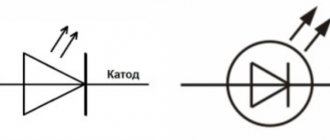
In the diagram, the LED is indicated as a regular diode with two parallel arrows pointing outward, indicating its emitting nature. There are a large number of types of LEDs on sale, which differ in functionality, design, power, glow color and other properties.
Based on their purpose, LEDs are divided into two types - indicator and lighting.
Indicative:
- SMD LEDs;
- super bright Super Flux “Piranha”;
- DIP LEDs (Direct In-line Package);
- Straw Hat (“straw hat”).
Lighting:
- COB (Chip On Board) LEDs;
- SMD LED;
- filament (Filament LED).
Indicative
Indicator LEDs are characterized by low power and moderate brightness. They are used for color indication of operating modes of various devices and equipment, as well as for illumination of displays and instrument panels. Types of indicator LEDs:
- DIP LEDs. The emitter crystal is located in an output housing, which most often is a convex lens. The downside is the small radiation scattering angle.
- “Piranha” is an ultra-high brightness emitter with four pins, ensuring its convenient mounting on the board. Demanded for illuminating devices in cars and advertising signs.
- "Straw Hat" A cylindrical two-terminal device with a significant radiation scattering angle and an increased lens diameter. Used in decorative structures and alarm lights.
- SMD LEDs. Ultra-high brightness devices are housed in housings designed for SMT mounting. Their markings indicate dimensions in inches (hundredths thereof) or in mm. LED strips are manufactured based on SMD LEDs.
Lighting
Lighting LEDs are found in the design of lanterns, headlights, and strips. They differ in the power and brightness of the glow. Most lighting fixtures are housed in SMT mounting housings. Available in two varieties of white:
- cool white – cold;
- warm white – warm.
An SMD lighting LED is a heat-sinking substrate on which a emitting crystal treated with a phosphor composition is mounted.
LED pinout
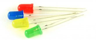
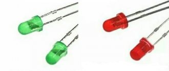
The polarity of the LED - anode or plus and cathode - minus is easy to determine from the pictures:
In cylindrical cases, the cathode is indicated by a cut on the side, the anode has a longer lead, and the cathode has a shorter lead.
The cathode of SMD LEDs is indicated by a cut on the body.
In high-power COB LED arrays, “+” and “-” are pressed onto solder pads.
LED connection diagram
In the classical circuit, it is recommended to connect through a current-limiting resistor. Indeed, by choosing the right resistor or inductive reactance, you can connect a diode designed for a 3V supply voltage, even to an alternating current network.
We recommend reading: Refinement of the Chinese super bright flashlight UltraFire XML-T6
The main requirement for power parameters is limiting the circuit current.
Since current strength is a parameter that reflects the density of electron flow through a conductor, if this parameter is exceeded, the diode will simply explode due to the instantaneous and significant release of heat on the semiconductor crystal.
Basic principles of connection
As mentioned earlier, the design of a light-emitting diode involves connecting them exclusively to a direct current source. However, since the working part of the LED is a semiconductor silicon crystal, it is very important to maintain polarity, otherwise the LED will not emit a luminous flux.
Each LED has technical documentation, which contains instructions and directions for correct connection. If there is no documentation, you can look at the LED markings. The marking will help you identify the manufacturer, and knowing the manufacturer, you can find the required datasheet, which contains information on the connection. Here, this is not a tricky piece of advice.
How to determine polarity?
There are only 3 ways to resolve the issue:
- Constructively. According to standards accepted throughout the world, on a regular LED (not SMD type), the long leg is always the “+” or the anode. For an LED to work, a positive half-wave must be supplied to it. And the short one is the cathode.
- Using a multimeter. To check, you need to set the device switch to the “Test” mode and install the red multimeter probe on the anode, and the black probe on the cathode. As a result, the LED should light up. If this does not happen, you need to change the polarity (black to the anode, and red to the cathode). If the result does not change, then the LED has failed (to establish a more accurate diagnosis, read how to check the LED).
- Visually. If you look closely at the LED, you can see 2 tips near the crystal. The larger one is the cathode, the smaller one is the anode.
We've sorted out the polarity, now we need to decide how to connect the LED to the network. For those who do not understand, read a detailed and interesting article on determining the polarity of an LED. In it we have collected all possible methods of checking, and even using a battery.
LED Polarity
LED Polarity
If turned on incorrectly, the LED may break. Therefore, it is important to be able to determine the polarity of a light source. Polarity is the ability to pass electric current in one direction.
Mono polarity can be determined in several ways:
- Visually. This is the easiest way. To find the plus and minus of a cylindrical diode with a glass bulb, you need to look inside. The cathode area will be larger than the anode area. If you can’t look inside, the polarity is determined by the contacts - the long leg corresponds to the positive electrode. SMD LEDs have markings indicating polarity. They are called a bevel or a key, which is aimed at the negative electrode. Small smds are marked with pictograms in the form of a triangle, the letter T or P. The corner or protrusion indicates the direction of the current - which means this pin is a minus. Also, some LEDs may have a mark that indicates polarity. It could be a dot, a ring strip.
- Using power connection. By applying a low voltage, you can check the polarity of the LED. To do this, you need a current source (battery, accumulator), to the contact of which an LED is applied, and a current-limiting resistor through which the connection occurs. The voltage needs to be increased and the LED should light up when turned on correctly.
- With the help of testers. The multimeter allows you to check the polarity in three ways. The first is in the resistance test position. When the red probe touches the anode and the black probe touches the cathode, a number other than 1 should light up on the display. Otherwise, the number 1 will light up on the screen. The second method is in the dial position. When the red probe touches the anode, the LED will light up. Otherwise he will not react. The third method is by installing an LED in the transistor socket. If a cathode is placed in hole C (collector), the LED will light up.
- According to technical documentation. Each LED has its own marking, which can be used to find information about the component. The polarity of the electrodes will also be indicated there.
The choice of polarity determination method depends on the situation and whether the user has the right tool.
Connecting a light-emitting diode to a 220 V network
If you power the LED directly from 220 V with its current limited, then it will shine with a positive half-wave and go out with a negative half-wave. But this is only in the case when the reverse voltage of the pn junction is much greater than 220 V. Usually this is around 380-400 V.
The second way to turn on is through a quenching capacitor.
The mains voltage is supplied to the “bridge” using diodes VD1-VD4. Capacitor C1 will “extinguish” about 215-217 V. The remainder will be straightened. After filtering by capacitor C2, a constant voltage is supplied to the LED. Don't forget to limit the current through the diode with a resistor
Another connection diagram is with a half-wave rectifier based on a diode and with a limiting resistor of 30 kOhm.
ATTENTION! Most circuits with a direct connection to a 220 V network have a serious drawback - they are dangerous for damaging a person with high voltage - 220 V. Therefore, they should be used carefully, with careful insulation of all live parts.
Connecting LEDs to 220V voltage
The first thing you need to know when connecting to a 220V network is that for a nominal glow, a current of 20 mA must pass through the LED, and the voltage drop across it should not exceed 2.2-3V. Based on this, it is necessary to calculate the value of the current-limiting resistor using the following formula:
in which 0.75 is the reliability coefficient of the led, U pit is the voltage of the power source, U pad is the voltage that drops across the light-emitting diode and creates the luminous flux, I is the rated current passing through it, and R is the nominal resistance for regulating the passing current After appropriate calculations, the resistance value should correspond to 30 kOhm.
However, do not forget that a large amount of heat will be generated at the resistance due to the voltage drop. For this reason, it is additionally necessary to calculate the power of this resistor using the formula:
For our case, U will be the difference between the supply voltage and the drop voltage across the LED. After appropriate calculations, to connect one LED, the resistance power should be 2W.
After determining the rating and power of the resistance, you can assemble a circuit to connect one LED to 220V. For its reliable operation, it is necessary to install an additional diode that will protect the light-emitting diode from breakdown when an amplitude voltage of 315V (220*√2) occurs at the LED terminals.
The circuit is practically not used, since very large losses occur in it due to heat generation in the resistance. Let's consider a more efficient connection diagram to 220 V:
In the diagram, as we can see, a reverse diode VD1 is installed, which passes both half-waves to the capacitor C1 with a capacity of 220 nF, on which the voltage drops to the required nominal value.
Resistance R1 with a nominal value of 240 kOhm discharges the capacitor when the network is turned off, and does not play any role during operation of the circuit.
But this is a simplified model for connecting LEDs; most LED lamps already have a built-in driver (circuit) that converts 220V AC voltage into 5-24V DC voltage for their reliable operation. You can see the driver circuit in the following photo:
We recommend reading: How to make an adjustable power supply from a charger
Nutritional Features
Considering the relatively high cost of ultra-bright LEDs, it is very important to use reliable and high-quality power supplies for their operation, since these semiconductor elements are critical to current overload.
After an abnormal operation, the device may remain operational, but the power of the emitted light flux will be significantly reduced. In addition, such an element is likely to cause damage to other LEDs connected together.
Before talking about drivers for ultra-bright LEDs, let's briefly talk about the features of their power supply. First of all, the following factors need to be taken into account:
- the power of the light flux emitted by these elements directly depends on the amount of electric current flowing through them;
- Ultra-bright LEDs are characterized by a nonlinear current-voltage characteristic (volt-ampere characteristic);
- temperature has a strong influence on the current-voltage characteristics of these semiconductor devices.
Below is shown the change in the current-voltage characteristic at the temperature of the semiconductor element (ultra-bright SMD LED) of 20 ° C and 70 ° C.
Changes in characteristics due to temperature influence
As can be seen from the graph, when a stable voltage of 2 V is applied to a semiconductor, the electric current passing through it changes depending on the temperature. When the crystal is heated to 20°C, it will be equal to 14 mA, when the temperature rises to 70°C, this parameter will correspond to 35 mA.
The result of such a difference will be a change in the power of the light flux at the same supply voltage. Based on this, it is necessary to stabilize not the voltage, but the electric current passing through the semiconductor.
Such power supplies are called LED drivers; they are ordinary current stabilizers. This device can be purchased ready-made or assembled yourself; in the next section we will provide several typical driver circuits.
Parallel connection of LEDs is not correct
Parallel connection of LEDs is used when the voltage of the power supply (source) is not enough in order to power a number of serial LEDs. If “specifically theoretically”, then LEDs can be connected in parallel and “stupidly” - connect all the anodes and cathodes of the LEDs. Then connect them to the battery and voila... The LEDs light up! Moreover, only once and for a short time when connected. Next - the end of them.
This circuit for connecting parallel light-emitting diodes is not workable, since the diode resistance is small and easily provokes a short circuit (short circuit).
I’ll immediately dismiss some of the spiteful critics. There are, of course, exceptions... Chinese manufacturers of cheap products are guilty of them. But this is an exception to the rule. If anyone has disassembled Chinese toys or lighters, they have probably seen just such a connection diagram. Where the diodes are connected in parallel, without any extraneous electronic components in their circuit. Why? Yes, everything is simple - in such circuits the current is limited by the internal resistance of the AG1 batteries (tablet). The power in such tablets is minimal and cannot harm the diode. Those. We again come to the conclusion that for normal operation, diodes need a resistor.
I repeat once again - parallel connection of LEDs is used only when the power source is low voltage.
Despite the fact that this type of connection is not very welcome, it is often used. There is one rule in these types of connections - parallel connection of LEDs is never done using ONLY ONE resistor!!!
Well, or for those who only understand visual pictures, an incorrect parallel connection will look like this:
Unfortunately, despite that. that this connection is not correct, again, the ubiquitous Chinese also use it to the fullest... Especially in flashlights. To do this, they overestimate the value of the resistor, so that there is no overload and the product can easily work for a year... Or maybe it won’t work... It depends on your luck.
Pros and cons of parallel LED connection
A big advantage of a parallel connection is that if the LEDs are connected correctly, if one of them burns out, the rest will work. The diodes will work if more LEDs burn out, the main rule here is that at least one branch should work. When LEDs are connected in series, failure of one of them will cause the row of series-connected chips to stop lighting.
A parallel connection allows you to connect two or more LEDs. Limitations can only arise in terms of battery power (power source) and the dimensions of the device itself in which you want to place your “brainchild”.
The disadvantage of parallel connection of LEDs is that the design becomes more expensive due to the fact that new elements appear in the circuit. As a result, the final product can be quite bulky.
It’s worth imagining a Christmas tree garland with such a connection of diodes... For it to work, you will have to connect another conductor to the LED-resistor pair. Therefore, 99.9% of all garlands are assembled from series-connected LEDs.
Serial connection
When connected in series through a current-limiting resistor, several LEDs are assembled into one chain, and the cathode of the previous one is soldered to the anode of the next one:
In the circuit, one current (20mA) will flow through all LEDs, and the voltage level will consist of the sum of the voltage drop across each. This means that using this connection diagram, you cannot include any number of LEDs in the circuit, because it is limited by voltage drop.
Voltage drop is the level of voltage that a light-emitting diode converts into light energy (glow).
For example, in the circuit the voltage drop across one LED will be 3 Volts. There are a total of 3 LEDs in the circuit. Power supply 12V. We consider 3 Volts * 3 led = 9 V - voltage drop.
After simple calculations, we see that we cannot include more than 4 LEDs (3 * 4 = 12V) in a parallel connection circuit, powering them from a regular car battery (or other source with a voltage of 12V).
If we want to connect more LEd in series, we will need a power supply with a higher rating.
This scheme was quite often found in Christmas tree garlands, however, due to one significant drawback, modern LED garlands use a mixed connection. We'll look at what the drawback is below.
We recommend reading: MOSFET transistors - what they are, operating principle
Disadvantages of daisy chaining
- If at least one element fails, the entire circuit becomes inoperative;
- To power a large number of LEDs you need a high voltage source.
LEDs and their applications
LEDs , or light-emitting diodes (LEDs, in the English version LED - light emitting diode) are a semiconductor device that emits incoherent light when an electric current is passed through it. The work is based on the physical phenomenon of the appearance of light radiation when an electric current passes through a pn junction. The color of the glow (the maximum wavelength of the emission spectrum) is determined by the type of semiconductor materials used that form the pn junction.
Advantages:
1. LEDs do not have any glass bulbs or filaments, which ensures high mechanical strength and reliability (shock and vibration resistance) 2. The absence of heating and high voltages guarantees a high level of electrical and fire safety 3. Inertia-free makes LEDs indispensable when high performance is required 4. Miniature 5. Long service life (durability) 6. High efficiency, 7. Relatively low supply voltages and current consumption, low power consumption 8. A large number of different glow colors, radiation directionality 9. Adjustable intensity
Flaws:
1. Relatively high cost. The money/lumen ratio for a conventional incandescent lamp compared to LEDs is approximately 100 times 2. Low luminous flux from one element 3. Degradation of LED parameters over time 4. Increased requirements for the power source
Appearance and main parameters:
LEDs have several basic parameters:
1. Housing type 2. Typical (operating) current 3. Voltage drop (operating) 4. Glow color (wavelength, nm) 5. Scattering angle
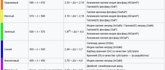
Basically, the body type refers to the diameter and color of the bulb (lens). As you know, an LED is a semiconductor device that must be powered with current. So the current that should be used to power a particular LED is called typical. At the same time, a certain voltage drops across the LED. The color of the radiation is determined both by the semiconductor materials used and by the doping impurities. The most important elements used in LEDs are: Aluminum (Al), Gallium (Ga), Indium (In), Phosphorus (P), causing a glow ranging from red to yellow. Indium (In), Gallium (Ga), Nitrogen (N) are used to produce blue and green luminescence. In addition, if a phosphor is added to the crystal that causes the blue (blue) glow, we get a white LED. The angle of radiation is also determined by the manufacturing characteristics of the materials, as well as the bulb (lens) of the LED.
Currently, LEDs have found application in a wide variety of areas: LED lights, automotive lighting, advertising signs, LED panels and indicators, tickers and traffic lights, etc.
Connection diagram and calculation of necessary parameters:
Since the LED is a semiconductor device, polarity must be observed when connected to the circuit. The LED has two terminals, one of which is the cathode (“minus”), and the other is the anode (“plus”).
only “light up” when turned on directly, as shown in the figure
When turned back on, the LED will not light up. Moreover, the LED may fail at low permissible reverse voltage values.
The current versus voltage dependences for forward (blue curve) and reverse (red curve) switching are shown in the following figure. It is easy to determine that each voltage value corresponds to its own current value flowing through the diode. The higher the voltage, the higher the current value (and the higher the brightness). For each LED, there are permissible values of supply voltage Umax and Umaxrev (for direct and reverse switching, respectively). When voltages above these values are applied, an electrical breakdown occurs, as a result of which the LED fails. There is also a minimum value of the supply voltage Umin at which the LED glows. The range of supply voltages between Umin and Umax is called the “working” zone, since this is where the LED operates.
1. There is one LED, how to connect it correctly in the simplest case?
To properly connect an LED in the simplest case, you need to connect it through a current-limiting resistor.
Example 1
There is an LED with an operating voltage of 3 volts and an operating current of 20 mA. You need to connect it to a 5 volt source.
Let's calculate the resistance of the current-limiting resistor
R = Uquenching / ILED Uquenching = Upower – ULED Upower = 5 V ULED = 3 V ILED = 20 mA = 0.02 A R = (5-3)/0.02= 100 Ohm = 0.1 kOhm
That is, you need to take a resistor with a resistance of 100 Ohms
PS You can use the on-line calculator to calculate a resistor for an LED
2. How to connect multiple LEDs?
We connect several LEDs in series or in parallel, calculating the required resistance.
Example 1.
LEDs are available with an operating voltage of 3 volts and an operating current of 20 mA. You need to connect 3 LEDs to a 15 volt source.
We make the calculation: 3 LEDs at 3 volts = 9 volts, that is, a 15 volt source is enough to turn on the LEDs in series
The calculation is similar to the previous example
R = Uquenching / ILED Uquenching = Upower – N * ULED Upower = 15 V ULED = 3 V ILED = 20 mA = 0.02 A R = (15-3*3)/0.02 = 300 Ohm = 0.3 kOhm
Example 2.
Let there be LEDs with an operating voltage of 3 volts and an operating current of 20 mA. You need to connect 4 LEDs to a 7 volt source
We make the calculation: 4 LEDs at 3 volts = 12 volts, which means we don’t have enough voltage to connect the LEDs in series, so we will connect them in series-parallel. Let's divide them into two groups of 2 LEDs. Now we need to calculate the current-limiting resistors. Similar to the previous paragraphs, we calculate the current-limiting resistors for each branch.
R = Uquenching/ILED Uquenching = Upower – N * ULED Upower = 7 V ULED = 3 V ILED = 20 mA = 0.02 A R = (7-2*3)/0.02 = 50 Ohm = 0.05 kOhm
Since the LEDs in the branches have the same parameters, the resistances in the branches are the same.
Example 3.
If there are LEDs of different brands, then we combine them in such a way that each branch contains LEDs of only ONE type (or with the same operating current). In this case, it is not necessary to maintain the same voltages, because we calculate our own resistance for each branch
For example, there are 5 different LEDs: 1st red voltage 3 volts 20 mA 2nd green voltage 2.5 volts 20 mA 3rd blue voltage 3 volts 50 mA 4th white voltage 2.7 volts 50 mA 5th yellow voltage 3.5 volts 30 mA
Since we divide the LEDs into groups according to current 1) 1st and 2nd 2) 3rd and 4th 3) 5th
We calculate the resistors for each branch: R = Uquenching/ILED Uquenching = Usupply – (ULEDY + ULEDX + ...) Usupply = 7 V ULED1 = 3 V ULED2 = 2.5 V ILED = 20 mA = 0.02 A R1 = (7-(3+2.5 ))/0.02 = 75 Ohm = 0.075 kOhm
similar R2 = 26 Ohm R3 = 117 Ohm
Similarly, you can arrange any number of LEDs
IMPORTANT NOTE!!!
When calculating the current-limiting resistance, we obtain numerical values that are not in the standard series of resistances, SO we select a resistor with a resistance slightly higher than calculated.
3. What will happen if there is a voltage source with a voltage of 3 volts (or less) and an LED with an operating voltage of 3 volts?
It is acceptable (BUT NOT DESIRED) to include an LED in a circuit without a current-limiting resistance. The disadvantages are obvious - the brightness depends on the supply voltage. It is better to use dc-dc converters (voltage boosting converters).
4. Is it possible to connect several LEDs with the same operating voltage of 3 volts in parallel to each other to a source of 3 volts (or less)? That’s how it’s done in “Chinese” lanterns.
Again, this is acceptable in amateur radio practice. Disadvantages of such inclusion: since LEDs have a certain spread in parameters, the following picture will be observed: some will glow brighter, while others will be dimmer, which is not aesthetically pleasing, which is what we see in the flashlights above. It is better to use dc-dc converters (voltage boosting converters).
RGB LEDs
Full-color LED or otherwise RGB LED - Red, Green, Blue. By mixing these three colors in different proportions you can display any color. For example, if you turn on all three colors at full power (Red: 100%, Green: 100%, Blue: 100%), you will get a white glow. If you light only two (Red: 100%, Green: 100%, Blue: 0%), the color will glow yellow.
Structurally, the RGB LED consists of three crystals under one housing and has 4 pins: one common and three color pins. RGB LEDs are: 1. Common anode (CA) 2. Common cathode (CC) 3. Without common anode or cathode (6 pins). Typically in SMD version.
The longest pin of an RGB LED is usually the common one (anode or cathode).
When connecting these LEDs, please note that the voltage supplied to illuminate the color may be different for different colors. For example, take a 5mm LED MCDL-5013RGB (I=20mA): Ured = 2.0 Volt Ugreen = 3.5 Volt Ublue = 3.5 Volt
It is also worth noting that for some types of RGB LEDs it is necessary to use a diffuser, otherwise the color components will be visible.
IMPORTANT NOTE!
The circuits presented above are not distinguished by the high accuracy of the calculated parameters, this is due to the fact that when current flows through the LED, heat is released in it, which leads to heating of the pn junction, the presence of a current-limiting resistance reduces this effect, but balance is established with a slightly increased current through Light-emitting diode. Therefore, it is advisable to use current stabilizers rather than voltage stabilizers to ensure stability. When using current stabilizers, you can connect only one branch of LEDs.
Tags:
- Light-emitting diode
Common connection errors
The most common mistakes when connecting LEDs:
- Choosing the wrong resistor value - if you choose too small a resistance, the LED may burn out. If the value is high, the diode will not shine at full strength.
- Connect directly to the power source without a current limiting resistor. The emitting component will immediately burn out.
- Parallel connection with one resistor for all diodes. Components will begin to fail because the operating current is different for each one.
- Connection in a series circuit of LEDs designed for different currents. In this case, some of the diodes will burn out, and some will shine dimmer.
- Connect directly to a 220 V network without protection.
Important! Making the described mistakes will entail negative consequences in the form of diode breakdown or self-injury.
220 volt ice driver circuit
A more reliable way to power LEDs from the network is to use a special converter or driver that reduces the voltage to a safe level. The main purpose of the driver for a 220 volt LED is to limit the current through it within the permissible value (according to the passport). It consists of a voltage driver, a rectifier bridge and a current stabilizer microcircuit.
Driver option without current stabilizer
If you want to assemble a 220 V LED power supply with your own hands, you will need to know the following:
- when using an output stabilizer, the ripple amplitude is significantly reduced;
- in this case, part of the power is lost on the microcircuit itself, which affects the brightness of the emitting devices;
- when using a large-capacity filter electrolyte instead of a proprietary stabilizer, the pulsations are not completely smoothed out, but remain within acceptable limits.
If you make your own driver, the circuit can be simplified by replacing the output microcircuit with an electrolyte.
Alternative connection type
Series-parallel connection of LEDs - found in floodlights and other powerful lamps operating on both direct and alternating voltage.
As you can see, the matrix is divided into branches, each of which has a current-limiting resistor. A specific copy is intended to replace the standard courtesy lamp in the car interior. If one diode fails, one circuit will stop lighting, and the remaining circuits will continue to glow.
If you can't decide whether to connect LEDs in series or parallel, there is an alternative option - a hybrid connection. At first glance, it is not clear what the point is.
The hybrid version takes advantage of the serial and parallel connection of LEDs. The circuit will work fully even if one of the elements in the circuit burns out, while at the same time the remaining elements will not experience overload. The voltage on each segment will be limited to the LED with the lowest drop.
To assemble the lamp correctly, and to ensure that the LEDs work for a long time and do not overheat, you need to decide how to connect the LEDs - in series or in parallel. You have become familiar with the strengths and weaknesses of each option. Thanks to the knowledge gained, you can repair an LED lamp or spotlight.
Use in everyday life
Most often, such circuits are found in backlit switches. A typical diagram of correct use is shown below:
Connecting an LED in a switch
Due to the low power of lighting devices, they do not have protective reverse diodes. The resistor is set to limit the forward current to 1 mA. This scheme for connecting an LED to a 220-volt network is not particularly effective in terms of the brightness of the glow, it is very dim, but it plays its role well - in a dark room the switch is visible. Here, the reverse voltage when the circuit contacts are opened is directed to a resistor; the presence of an LED or any other light bulb, as well as a power supply, also acts as an additional load. Thus, the LED is protected from reverse current breakdown.
Homemade LED driver
We will present to your attention several driver options based on specialized microcircuits from the Monolithic Power System company, the use of which significantly simplifies the design. The circuits are given as an example; a full description of the typical connection can be found in the datasheet for the microcircuits.
Option one is based on the MP4688 step-down converter.
Example of turning on MP4688
This driver can operate with voltages from 4.5 to 80 V, the maximum output current threshold is 2 A, which allows you to power a lamp using ultra-bright high-power LEDs. The level of electrical current passing through the LEDs is controlled by the RFB resistance. The implementation of PWM dimming with a frequency of 20 kHz allows you to smoothly change the electric current flowing through the LED.
The second version of the driver is based on the MP2489 chip. Its compact housing (QFN8 or TSOT23-5) makes it possible to place the driver in the MR16 socket used by halogen lamps, which allows replacing the latter with LED lamps. A typical MP2489 connection diagram is shown in the figure.
Driver based on MP2489
The above circuit allows you to connect two parallel LEDs, each with an operating current of 350 mA.
The latest version of the driver based on the MP3412 chip, which can be used in portable flashlights. A distinctive feature of this circuit is the ability to operate from an AA finger-type battery.
Driver for flashlight based on MP3412
Safety precautions
Briefly about the nuances of the connection, which is carried out in most homes - to ensure safety when working with an electrical circuit, it is often not enough to turn off just the switch. The fact is that it, as a rule, opens the phase, but due to the lack of grounding, a residual voltage remains at zero. If the grounding is incorrect, for example, people connect to a battery or water supply, there is a risk of getting voltage between the phase and ground. Turn off the power completely at the switch or meter at the entrance to the house or apartment, and make proper grounding if you do not have one.
Interior lighting
LED lamps used for indoor lighting, as a rule, consume power of several tens of W (20...60 W) and, accordingly, power supplies for lamps of this type must have power factor correction (PFC). The operating conditions in this case are quite mild (temperature range 0/-10°C ... 40/45°C according to [1]), increased protection from external influences (IP) is not required. On the other hand, in this type of lighting the coefficient of illumination ripple is normalized, so it is necessary to pay attention to the current ripple of the selected source.
Power supplies for lighting rooms with reduced requirements for light pulsation
New power supplies for this lighting segment, which have already appeared on the market or are expected to begin in the fall of this year, are presented mainly by the manufacturer MEAN WELL (Table 1, Figure 1).
Table 1. Eaglerise and MEAN WELL power supplies with reduced ripple current requirements
| Name | Power, W | Current, mA | Kp, % | KM, l l | Efficiency, % | Operating temperature range, °C | Manufacturer | Control |
| PLD-40/60 | 40/60 | 350, 700, 1050, 1400, 1750, 2100, 2400 | ~20 | >0,95 | ~86 | -30…50 | MEAN WELL | No |
| PCD-40/60 | 40/60 | ~86 | TRIAC | |||||
| PLM-25 (expected in autumn 2013) (expected in autumn 2013) | 25 | 350, 500, 700, 1400 | ~83 | -30…60 | No |
Rice. 1. Appearance of power supplies of the PCD/PLD, PLM, ELP/LS series
The sources are made in IP20 plastic housings with protection from external influences, have an electrical insulation strength corresponding to electrical safety class II, a universal input voltage range of 90...264 V (except PLM-25) and an active power factor correction circuit with l>0.95 , performed according to a single-stage conversion circuit.
The PLM-25 series has just been announced, is expected on the market by the fall of this year, has a Slim form factor; overall dimensions are 145x38x22 mm. In order to further reduce costs in this model, the manufacturer abandoned the universal input (90...264 V), but chose an input voltage range expanded in the area of the maximum value. The input voltage range for this model is 180…295 V. The increased upper value of the input voltage should increase the reliability of the power supply in case of possible overvoltages in the network.
The power supplies presented in Table 1 are characterized by low cost and good reliability, but have a current ripple of 10...25%. Therefore, the sources are optimally suited for lighting trading floors, rooms for performing visual work of medium and low precision, as well as for lighting rooms with temporary occupancy of people.
Power supplies for lighting rooms with stringent requirements for light pulsation
To illuminate offices and premises for performing visual work of high, very high and highest accuracy, the sources indicated in Table 2 are successfully used. The general view of the sources is shown in Figure 2.
Table 2. Power sources for lighting rooms with stringent requirements for light pulsation
| Name | Power, W | Current, mA | Kp, % | KM, l l | Efficiency, % | Operating temperature range, °C | Manufacturer | Control |
| LST IPS30-350T | 30 | 350 | <1 | >0,95 | ~88 | -20…50 | Argos | No |
| LST IPS40-700T LST IPS40-700TP[400-700] | 40 | 700 (400…700) | manual adjustment | |||||
| LST IPS50-350T LST IPS50-350 TP[240-360] | 50 | 350 (240…360) | ||||||
| LST IPS60-350T | 60 | 350 | No | |||||
| LST IPS60-700 TP[400-700] | 60 | 400…700 | manual adjustment | |||||
| ELP040C0350LX | 40 | 350 | <0,5 | >0,95 | ~87 | -10…50 | Eaglerise | No |
| ELP040C0500LX | 40 | 500 | ||||||
| ELP040C0700LX | 40 | 700 | ||||||
| ELP060C0700LX | 60 | 700 |
Rice. 2. Appearance of sources for lighting rooms with strict requirements for light pulsations
The main feature of the power supplies discussed in Table 2 is that they simultaneously perform power factor correction and have extremely low current ripple. The choice of power supplies at an adequate cost with similar characteristics in the power range up to 50 W is currently quite narrow, so we can take a closer look at the presented models.
These products have very similar characteristics and almost the same cost, but they also have differences. They consist in the fact that Argos products have class I protection against electric shock, and Eaglerise products correspond to protection class II and, in addition, meet the requirements for a SELV source. Using the products of this manufacturer as a remote power supply, it is possible to produce lamps that meet the highest protection class III.
To control lighting products, the DALI (Digital Addressable Lighting Interface) protocol, specially developed for this purpose, is widely used. This protocol makes it very easy to install luminaires into a controlled system and has such flexibility that without any special costs, using only software, you can always change the control algorithm for individual components in this system. A fairly wide range of elements for organizing a control system using the DALI protocol is presented by Osram. For luminaires that could operate in such a system, a power source that supports the DALI control protocol is required.
MEAN WELL has developed a new family of LCM that support this control protocol. LCM-40DA and LCM-60DA series (Figure 3, Table 3). As part of this family, a series of sources controlled via the 1-10 V and PWM protocol will also be produced (models without the DA suffix): LCM-40 and LCM-60 .
Rice. 3. Appearance of sources controlled via the DALI protocol: LCM-40(DA)/60(DA)
Table 3. Main technical characteristics of power supplies of the LCM family
| Name | Power, W | Current, mA | Kp, % | KM, l l | Efficiency, % | Operating temperature range, °C | Manufacturer | Control |
| LCM-40DA | 35…42, depends on the output current value | 350, 500, 600, 700, 900, 1050 | <5 | >0,95 | 90% | -30…60 | MEAN WELL | DALI |
| LCM-60DA | 45…60, depends on the output current value | 500, 600, 700, 900, 1050, 1400 | 92% | DALI | ||||
| LCM-40 | 35…42, depends on the output current value | 350, 500, 600, 700, 900, 1050 | 90% | 1-10 V; PWM | ||||
| LCM-60 | 45…60, depends on the output current value | 500, 600, 700, 900, 1050, 1400 | 92% | 1-10 V; PWM |
These sources allow you to select the initial value of the output current using a jumper (DIP switch), have an active power correction circuit, small current ripple (less than 5%) and an extended input voltage range of 180...295 V in the upper value region; are produced in a plastic case, made according to electrical safety class II. The sources allow you to connect an external thermistor (NTC) for additional protection of the LEDs from overheating in the event of any emergency. By choosing a thermistor rating in the range of 220...470 kOhm, you can set a limit temperature in the range of 60...80°C, above which the current will begin to automatically decrease. These source models have an additional DC voltage output of 12 V/0.05 A, which can be used for an external fan, powering some additional sensor or other purposes.
Judging by the stated parameters, the source promises to be of very high quality and with a full functional set required from products of this kind. These sources have been ordered to the COMPEL warehouse and are expected in the near future (tentatively the end of May).
Power supplies for industrial lighting
To illuminate workshops of industrial enterprises, warehouses or other premises with fairly high ceilings (6...12 m), as a rule, LED lamps with a power in the range of 60...250 W are used. In terms of electrical and design parameters, the new MEAN WELL HBG (Figure 4, Table 4). These products have been announced and will become available for order in the near future.
Rice. 4. Appearance of HBG series sources
Table 4. Main technical characteristics of LPF and HBG
| Name | Power, W | Current, A | Kp, % | KM, l l | Efficiency, % | Operating temperature range, °C | Manufacturer | Control |
| HBG-100 | 100 | 1,6; 2; 2,7; 4 | <5 | >0,95 | 91 | -40…70 | MEAN WELL | available with index B 1-10 V; PWM; R |
| HBG-160 | 160 | 2,6; 3,3; 4,4; 6,5 | 92 | |||||
| HBG-240 | 240 | 4; 5; 6,7; 10 | 93 |
The sources of the new HBG series have an unusual round form factor. There are practically no power supplies in this design and with similar power on the market; we can say this will be the first product. On the other hand, if we proceed from the appearance of lamps made with traditional light sources, then this form is the most common for this type of lamps (High Bay). The HBG series, due to its high power, is manufactured in a metal case filled with a compound to IP65/67. These sources have increased reliability - a manufacturer's warranty is expected for a period of 5 years, and the service life is estimated to be at least 40 thousand hours at a case temperature of 70°C.
The products are operational in the full range of input voltages 90…305 V. It is expected that this series will have models with dimming capabilities. Since these sources have a current ripple of less than 5%, they can be used to illuminate workshops where there is equipment with rotating parts (lathes) and where visual work is performed with the highest precision.