Engineers and simply enthusiasts in the world of electronics quite often need to carry out some measurements, one of which is power measurement. Therefore, in this article we will look at creating a homemade wattmeter based on an Arduino board, with which you can measure voltage, current and power of an electrical signal.
Some may say why make such a device if you can now buy it relatively inexpensively. Yes it is. But surely some of you want to make a more advanced wattmeter than the one you can just buy. Using an Arduino board to create a wattmeter, we can display measured values on a computer screen, plot them, save their values to an SD card when their values are within specified intervals, and much more.
Required Components
- Arduino Nano board (buy on AliExpress).
- Operational amplifier LM358 (buy on AliExpress).
- Voltage regulator LM7805 (buy on AliExpress).
- LCD display 16x2 (buy on AliExpress).
- Shunt resistor 0.22 ohm 2Watt (buy on AliExpress).
- Trimmer potentiometer 10 kOhm (Trimmer pot) (buy on AliExpress).
- Resistors 10 kOhm, 20 kOhm, 2.2 kOhm, 1 kOhm (buy on AliExpress).
- Capacitors 0.1 uF (buy on AliExpress).
- Test load.
- Perforated or breadboard.
Circuit operation
The wattmeter circuit based on the Arduino board is shown in the following figure.
To make it easier to understand, the diagram is divided into 2 parts. The upper part of the circuit is its measuring part, and the lower part of the circuit is used to carry out calculations and display their results. The connection points of both parts of the circuit are indicated using labels.
The circuit is designed to operate with voltage in the range of 0-24V with a current of 0-1A - these parameters are specially selected to work with Solar PV (solar photovoltaic system). But if you understand the principles of operation of this circuit, you can easily expand the ranges of its operation to the ones you need. The fundamental operating principle of this circuit is to measure the voltage and current in the load in order to then calculate the power consumed by the load. The values of all measured parameters will be displayed on the 16x2 LCD screen.
Next, let's look at the individual operation of small elements of the presented circuit in order to better understand its operation.
Measuring unit
The measurement block of the circuit consists of a voltage divider with two resistors to measure the voltage value and a shunt resistor with a non-inverted op-amp to measure the current. The voltage divider is shown in the following figure:
The input voltage in this circuit is designated Vcc. As we said earlier, the circuit is designed to measure voltages from 0V to 24V. But the Arduino board cannot measure such large voltages - it can only measure voltages in the range of 0-5V. Accordingly, we must convert the measured voltage in the range of 0-24V to the range of 0-5V. This conversion is precisely carried out using the presented voltage divider. Accordingly, the resistor values in the circuit of this divider (10 kOhm and 2.2 kOhm) are precisely selected in such a way as to convert the 0-24V range to the 0-5V range. If you need to change the range of voltages measured by the circuit, you just need to change the values of the resistors in the presented voltage divider circuit. The voltage value at the output of the voltage divider can be calculated using the well-known formula:
Vout = (Vin × R2) / (R1 + R2)
The voltage converted to the 0-5V range from the midpoint of the voltage divider is indicated in our diagram with the Voltage label. Subsequently, this converted voltage value is supplied to the analog input of the Arduino board.
Next we must measure the current through the load (LOAD). Since microcontrollers can only read analog voltage values, we need to convert the current value to a voltage value. This can be done by adding a shunt resistor - according to Ohm's law, the voltage drop across it will be proportional to the current flowing through it. Since the voltage drop across the shunt resistor will be very small, we will use an op-amp to amplify it. The diagram for carrying out this process is shown in the following figure:
The resistance value of the shunt resistor (SR1) in our case is 0.22 Ohm. As stated earlier, our circuit is designed to measure current in the 0-1A range, so according to Ohm's Law, at a maximum current through a 1A load, the voltage drop across our shunt resistor will be approximately 0.2V. This voltage is too low to be read by the microcontroller, so we use an op-amp in non-inverted amplification mode to amplify this voltage to a value that can be comfortably read by the Arduino board.
The op amp in non-inverted mode is shown in the above diagram. The amplifier is designed in such a way that its gain is 21, resulting in 0.2*21 = 4.2V. The formula for calculating the gain of the presented operational amplifier is as follows:
Gain = Vout / Vin = 1 + (Rf / Rin)
If you need to change the range of current values measured by the circuit, you need to change the resistance value of the shunt resistor, as well as the resistance values of the resistors that affect the gain of the operational amplifier.
In our case, the value of resistor Rf is 20 kΩ and the value of resistor Rin is 1 kΩ, which provides a gain of 21 for the op-amp. Next, the voltage from the output of the operational amplifier is supplied to an RC filter consisting of a 1 kOhm resistor and a 0.1 μF capacitor. This filter is designed to filter out unwanted noise. Next, the filtered voltage is supplied to the analog input of the Arduino board.
And finally, the last component that we need to consider in the measurement unit of our circuit is the voltage regulator. Since we are supplying a variable voltage to the input of the circuit, we need a stabilized voltage of +5V to power the Arduino board and operational amplifier. This regulated (stabilized) voltage in our circuit is provided by the 7805 voltage regulator. A capacitor is added at the output of the regulator circuit to filter out noise.
Block of calculations and information display
In the measurement block, we designed a circuit to convert the measured values and currents into a voltage range of 0-5V, which are directly fed to the analog inputs of the Arduino. In the same part of the circuit, we connect these voltage wires to the Arduino board, and also connect an alphanumeric LCD display to the Arduino board to display the measurement results. The diagram of this block is shown in the following figure.
As you can see from the diagram, the voltage pin is connected to analog pin A3, and the current pin is connected to analog pin A4 of the Arduino board. The LCD display is powered by +5V from the 7805 regulator and connected to the digital pins of the Arduino board in 4-bit mode. We also use a 10k ohm potentiometer connected to the Con pin of the LCD to adjust its contrast.
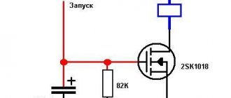
Now it's more interesting
Let's combine a potentiometer and a diode. And we will have smooth control of the brightness of the LED. We connect everything according to the following diagram:
After connecting, let's write the code for our improvised lamp:
int pot = A0; // potentiometer is connected to A0 int val; // variable for storing values int LED = 3; // LED is connected to pin 3 void setup() { Serial.begin(9600); // set the data exchange rate to 9600 bits per second pinMode(pot, INPUT); pinMode(LED, OUTPUT); } void loop() { val = analogRead(pot); // read data from the potentiometer Serial.println(val); // print the values from a new line val = val / 4; // divide the values from the potentiometer by 4 analogWrite(LED, val); // display the value of the variable, which we get after dividing by 4 }
Short explanations of the code. Dividing by 4 is necessary for the following. The potentiometer can take values from 0 to 1023. But the analog input/output transmits values only in the range from 0 to 255. Therefore, in this case, we simply need division.
How to improve measurement accuracy
This approach to measuring current and voltage works quite well, but has the disadvantage that the relationship between the measured voltage at the ADC output and the actual voltage value is not completely linear, so simple multiplication in the program cannot provide very high accuracy measurements.
To increase the measurement accuracy, we can build a set of measured values from the ADC output with a set of corresponding real voltage values, then use these two sets to build a graph and, based on it, calculate the required coefficient for multiplication using the linear regression method.
Finally, when we know the current and voltage values, we can calculate the power using the well-known formula P=V*I and then display all these three values on the LCD screen.
Testing the project's operation
To assemble the circuit, we used a perforated board as shown in the figure below. We used a Phoenix clamp terminal to connect the load and a normal DC barrel Jack to then connect to the voltage source.
Once the hardware of the project is ready, upload the program code to the Arduino Nano board. Use the potentiometer to adjust the contrast of the LCD display. To test the operation of the circuit, connect the load and power source. The power supply voltage must be at least 6V since the Arduino board requires a voltage of +5V for its operation. If the circuit is working as expected, you should see the measured voltage and current values, as well as the calculated power value, on the LCD screen. These processes are shown in more detail in the video at the end of the article.
To calibrate our wattmeter, you can use some “factory” wattmeter. Using the capabilities of the Arduino platform, you can significantly improve the functionality of this project - add a data logger to an SD card, plotting, notifications about some situations (for example, when voltage and current values go beyond the permissible values) and much more.
On our website you can also see similar projects:
- ohmmeter on Arduino;
- ammeter on Arduino;
- voltmeter on Arduino.
map() function
Map is a mathematical function that converts the value of a variable from one range to another. The function in the code looks like this: map(value, fromLow, fromHigh, toLow, toHigh). It is this that can replace division in our code. And in general, this function is quite often useful when working with Arduino. So our code now looks like this:
int pot = A0; // potentiometer is connected to A0 int val; // variable for storing values int LED = 3; // LED is connected to pin 3 void setup() { Serial.begin(9600); // set the data exchange rate to 9600 bits per second pinMode(pot, INPUT); pinMode(LED, OUTPUT); } void loop() { val = analogRead(pot); // read data from the potentiometer Serial.println(val); // print the values from a new line val = map(val, 0, 1023, 0, 255); // use the function analogWrite(LED, val); }
This concludes the third part. Thank you for your attention.