Schemes of a 12V turn-on delay relay on a transistor + RC and ne555 for cars. TOP 5 popular transistors. 3 most frequently asked questions. Mini test. Let's look at 2 questions on the topic.
TEST:
Mini test for 4 questions.
We test ourselves for knowledge of the theory. What current will flow through the resistor if the voltage is 12V and the resistance is 200 Ohm?
A) 6A;
B)16mA;
B)0.06mA;
Please indicate the correct statement.
A) When connecting a positive potential to a p type junction and a negative potential to an n type junction, the current will be forward biased.
B) When connecting negative. potential to a p-type junction, and a negative one to an n-type junction, the current will be directly biased.
What is the difference between a field-effect transistor and a bipolar one?
A) Type of control of the output signal.
B) The number of pn transitions.
B) Internal structure.
A schematic representation of which is shown in the picture below.
A) Power source.
B) Capacitor. Answers on questions
Answer B). The current is calculated according to Ohm's law U=R*I. We substitute the variables and transform the equation 12V=200Ohm*I; I=12V/200 Ohm=0.06mA. Answer A). When + is connected to a p-type electrode, and – to an n-type electrode, a forward bias will occur, and current will flow in the circuit. If it’s the other way around, the current in the circuit will be minimal. All statements here are true! Answer B). This is a polarized capacitor
A turn-on delay relay is often called a timer or time relay in electrical and radio engineering literature.
An electronic delay relay is a device that functions as a time counter. After the specified interval has expired, the device turns on/off the devices it controls. Thanks to the ability to program the timer, the device has found wide application where cyclic switching of the operating modes of all devices connected to the relay is required.
The definition is generalized and is suitable for systems using integrated circuits (ICs) of the ne555 type. There are other ways to design timers without using an IC.
Using a capacitor paired with a resistor and transistor
Delay turning off and turning on the relay using a capacitor and 12V resistor
It is not necessary to resort to using integral timers like the NE555 if you only need a delay before start/stop. Using a capacitor paired with a resistor and transistor will solve the problem without complex ICs. Use the diagram below
This is a classic circuit using a capacitor, resistor, diode and bipolar transistor. The circuit uses an NPN type transistor. It works like this: after applying voltage to resistor N resistance, capacitor N capacitor begins to charge. When the bias voltage is reached, the diodes open, and then the control emitter pn junction of the transistor opens, which “opens” the transistor and the current begins to flow in the collector-emitter direction.
Our semiconductor operates in active mode. Until the current controlling the base leaves this mode, the gain will not take on a descending form. This continues until the current value completely crosses the cutoff threshold - the collector-emitter junction closes. When turned on, the opposite happens.
For assembly, it is recommended to use a KT827 transistor with an npn junction. The diode is suitable KD105B or similar in parameters. The capacitor and resistor are selected individually in each case, more on this below.
Operating principle of protective devices
To protect against electrical impulses caused by lightning, a lightning arrester is installed together with an SPD. And you can protect the line from the flow of electrons, the parameters of which do not correspond to the operating characteristics of the network, using special sensors, as well as overvoltage relays.
It should be said that both the DPN and the relay differ in principle of operation and purpose from the stabilizer.
The task of these elements is to stop the supply of electricity if the value of the difference exceeds the maximum threshold specified in the technical data sheet of the protective device or set by the regulator.
After normalizing the parameters of the electrical line, the relay switches on automatically. DPS for line protection should be installed only in conjunction with a residual current device. Its task is to cause a current leak when a malfunction is detected, under the influence of which the RCD will trip.
Visually about the voltage relay in the video:
The disadvantage of this circuit is that it needs to be turned on manually after the voltage returns to normal. In this regard, a voltage stabilizer compares favorably. This device provides an adjustable time delay for current delivery if it is triggered by excessive voltage. The stabilizer is often used to connect air conditioners and refrigeration units.
How to calculate delays on rc circuits for 12V relays
The RC circuit is based on several phenomena and properties of a capacitor: to accumulate opposite charges on its plates, without passing current through itself, and instantly release the charge back into the circuit. Due to the fact that the two plates of the capacitor are insulated with a dielectric, “stirring” occurs in the external circuit during discharge or charging.
Another useful property of a capacitor is that as it charges, the voltage equals the voltage of the charge source, after which the current in the circuit stops flowing because potentials are equalized. The duration of charging the condenser depends on its capacity and the resistance of the source.
But what does instantaneous discharge of a capacitor give us if a delay is required? Nothing. Therefore, a passive semiconductor - a resistor - comes to the rescue.
The only function of a resistor is to limit the current by dissipating the excess as heat. By adjusting the current, you can set the charging or discharging time of the capacitor. The greater the current resistance and capacitance of the capacitor, the longer it will take to discharge and charge.
All this suggests an obvious conclusion - a capacitor paired with a resistor will serve well as a timer.
How to calculate and make a delay for turning on a 12V relay for 3 seconds
As we found out, the delay time directly depends on the capacitance and resistance. This formula is useful for the calculation:
T=RC,
where T is time in seconds, R is the resistance, in our case a resistor, and C is the capacitance of the capacitor in farads.
IMPORTANT! Capacitance is calculated in farads. Typical Conders have capacitance in microfarads or even pico and nanofarads, so all calculations are converted to SI (International System of Units). 1 microfarad is 10-6 (power) and equals 0.000001 farad!
There is no point in installing a large capacitor. The 1 farad capacitance is so huge that it cannot be grasped with one hand. Therefore, we use a capacitor of 50 uF or more and select a resistor.
Now we use the formula above and substitute the parameters of the elements in place of the variables:
3с=R*0.00005;
Let's transform the equation:
R=3c/0.00005=60,000Ohm
This is how we found the required resistor so that the 50 µF condenser would be charged within approximately 3 seconds. Its resistance is 60,000 Ohm => 60 kOhm. Do not forget that the conductor also has its own resistance, but it makes no sense to take it into account in our calculations, because Latencies will increase by milliseconds or less.
Programming microprocessor devices
As described earlier, microprocessor devices became a milestone in the development of time relays. The essence of what they are needed for is the versatility of the device. It can be programmed to perform the functions of turning off, turning on, maintaining line activity for a set period, and all of the above can be done without changing the design of the device itself. Any complexity of operations will be performed using just one microcircuit located on the device board.
In addition to these features, a nice bonus is the expansion of functionality through communication interfaces with smart home systems. The latter can not only monitor the state of the time relay, but also set its parameters or directly influence the shutdown mechanisms.
For example, a universal two-channel programmable time relay UT24 from the Aries production association is shown in the picture below:
To program its timers, you need to refer to the block diagram and follow the steps; you can find out the purpose of the configured item in the user manual, which comes with each device:
As you can see, microprocessor devices seem complex only at first glance, but once you understand a little, you can easily use them for your purposes and configure them.
Turning on a 12V relay with a delay on a capacitor and resistor without a diode
Turning on a 12V relay with a delay on a capacitor and resistor without a diode.
In the circuit discussed earlier, there were two diodes. They were used to quickly discharge the capacitor when changing polarity. The effect of instant attenuation of the system occurred, without delays. Now we are presented with a circuit with a delay for turning off and turning on without diodes. It uses an N-channel field-effect transistor - a power mosfet. The field switch is controlled by voltage, not current, so this approach is less current-hungry - this is a very big plus.
An N-channel mosfet opens when a positive potential is applied to the gate relative to the source. An 82kOhm resistor is pulled to ground to close the transistor when the power is cut off, because The mosfet will not turn off on its own. Another function of the resistor when connected in parallel with the conductor is to limit the current supplied to the gate. To adjust the delay time, it is necessary to experimentally select the capacitance of the condenser and the resistance of the circuit. According to experiments, an 82 kOhm resistor paired with a 470 uF capacitor shows a delay time of 55 seconds.
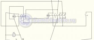
Diagram of a 12 volt time relay (RT) with a shutdown delay for a car
Scheme of a time relay (RT) 12 volts with a shutdown delay for a car
GOST R 50571.3-94 clause 412.1 requires that all current-carrying conductors be covered with insulation. Clause 411.1.3.1 reminds you that all electrical lines of devices in the circuit must be separated from each other.
Let's take a closer look at the 12 volt connection diagram with a turn-on delay for a car. +12 we take from the cigarette lighter, out +12 is a mounted device, which is controlled using a relay, GND – ground, IN – control, connects to something that will switch our relay. C1 and R1 are responsible for the shutdown delay time. In order for field switch V1 to close, there must be no voltage at the gate. R1 pulled to the ground will take care of this. R1 also acts as a voltage regulator at the gate of V1.
The formula T=RC will calculate the required ratings R1 and C1. For a more accurate calculation, it is also necessary to take into account the gate-source resistance and the relay release current. Therefore, it is easier to find the values of elements using the selection method rather than calculations using formulas. According to experiments, a 5 μF capacitor and a 1 MΩ resistor are enough for 10 seconds of delay
Main characteristics of the device
In specialized retail outlets there are delay devices with different characteristics, produced by different manufacturers. The quality of products from renowned manufacturers is confirmed by certificates and the service life they guarantee. Popular companies include: Hager, Asko, Eaton, ABB, Schneider, Novatek. Regardless of the type and model, time relays are characterized by the following parameters:
Connecting the device usually does not cause problems. The device is connected to a break in the line suitable for the load. Each relay must come with instructions from the manufacturer with a detailed connection diagram and description. Moreover, it can also be depicted on the device body itself.
Do-it-yourself 12V turn-on delay relay (RD) on the ne555 and k561ie10 microcircuit
Ne555 - IC, a device for generating pulses at certain intervals, in simple terms - a timer, in technical terms. In the literature, the monovibrator k561ie10 is an analogue of the ne555, but only a dual multivibrator in one housing.
12V turn-on delay relay (RD) on ne555 and k561ie10 microcircuit
Above is a delay circuit for turning on a 12V relay without transistors using the ne555 universal timer. Capacitor C1 and resistor R1 are responsible for the delay time. Use the formula shown in the picture above to calculate the delay time. Note that the constant variable 1.1 is used here and its use is mandatory.
The device works approximately like this: after power is applied, the timer starts, then after the time has elapsed, pin 3 of the OUT chip generates a pulse that closes the relay. Diode VD2 is installed to ensure reliable operation of the relay. VD1 protects the timer from random pulses from the power supply side of the IC.
Automotive timing relay 12 volts with DRL activation delay on 555 timer
We have already considered an example with a turn-off delay using a time-setting RC circuit and a transistor. Now let's do the same thing only using the ne555 timer for DRLs. We will need a ne555 monoborator, 3 25V conductors for 10.22.0.1 µF, one diode of any kind. The pictures below show the upgrade of relay 23.3787. We do everything by analogy. C1 and R1 set the delay. A capacitance of 10 μF and 1.3 MΩ is enough for about 10-13 seconds, so if this is not enough or a lot, we use the formula T = 1.1 * RC for calculation.
Automotive timing relay 12 volts with DRL activation delay on 555 timer
Delay relay circuit on ne555 turn off 24V with your own hands without a transformer
Do not forget that the current PUE regulates the grounding requirements for all devices operating from a 380V network. And devices operating from 42-380V AC must be grounded in places and rooms with increased fire hazard. IEC 364-4-41 requires the grounding of all devices operating at a voltage of 50V and above, and the grounding of devices from 25V in particularly hazardous areas.
Delay relay circuit on ne555 switch off 24V without transformer
According to the principle of operation, the previous circuit differs only in the addition of a voltage multiplier assembled on diodes VD1, VD2 and capacitors C3, C4. The multiplier can only operate in an AC circuit due to the fact that in the first half-cycle, one section of the diode + conductor is charged, and in the second half-cycle, the second assembly is charged. Periodic changes in the direction and magnitude of the current are not typical for constant voltage. Our connectors are connected in series, so the sum of their voltages doubles, and the output becomes 24V.
What are the types?
Electronic types
This is the most common variety. They have a process control function with a delay of a few fractions of seconds. The continuous operation time is several thousand hours. They are small, consume little electricity and have different additional functions depending on the manufacturer.
Electromagnetic retardation devices
They require direct current to operate. During the increase in the main magnetic current, the delay of the device is triggered, so another flux is created in the additional winding, which prevents the main one from increasing.
Pulse or bistable relay
—Pulse relays differ from electronic ones in that when a voltage pulse is applied to them, it turns on, when the next pulse is applied, it turns off. It is used in automation and security systems. When a pulse is given from one polarity, the armature occupies one position, simultaneously closing a pair of contacts. When a pulse of reverse polarity is applied, the armature occupies a diametrically opposite voltage, also closing a pair of contacts.
Pressure switch
—Pressure switch—designed to automate the water supply system. It is responsible for turning the pump on and off automatically when the water pressure changes
With pneumatic retardation
This type has a pneumatic damper. To adjust the time, you need to change the cross-section of the hole. These devices have a large number of contacts that can transition from a normally open to a normally closed state. This type of switch is used where sequential control is needed. Their coils are easily replaced, and the time delay ranges from 0.4 to 180 seconds.
Devices with a clock or anchor mechanism
They work using a spring that is driven under an electromagnet. The anchor mechanism begins to work when the specified time is set on the scale. The 2РВМ device is a classic representative of this variety. Its purpose is to control two electrical circuits (independent) for closing and opening. They are controlled thanks to daily programs, which are installed by installing pins in two special disks.
Motor devices
They are distinguished by a high time delay - from five seconds to three to five hours.
Software relay
It is used for communication of electric motors, automation of local circuits and lighting loads. They differ from other types in that the contacts are made of silver, and from programmable logic controllers in a small number of input/output channels, a small amount of memory and the inability to perform complex mathematical operations.
Delay for turning on the 5V relay after powering up the Arduino
Turning on the 5V relay after powering up the Arduino.
To make a time relay on Arduino we will need:
- Arduino uno module – 1000-1200 rubles;
- 1 button – 5 rubles;
- Relay 5V Arduino PIC ARM – in China costs 100-200 rubles;
- 5V power supply - they cost pennies, even a computer ATX power supply unit or a mobile phone charger power supply unit will be useful if powered correctly;
- Trimmer resistor;
Video. How to make a 5V time relay on Arduino
Watch the video attached above, where the author explains in detail how to connect and program an Arduino for a time relay. Let's add that the delay time is controlled by a trimming resistor.
Using and connecting a time relay
Schematic diagram
I looked at many circuits for protecting speakers, I wanted to find a universal option with a minimum of electronic components, of all the circuits one clearly stood out - I found it in the magazine RADIO No. 5 for 1998, author of the publication: Yu. Zalisky (Lvov, Ukraine) .
In addition to fulfilling all the points I mentioned above, it is built using only two transistors and provides reliable speaker protection for two channels of the low-frequency amplifier.
Fig.1. Scheme of the device for switching on delay and protection of acoustic systems (AS).
What else is important to know? 2 interesting facts
3T=RC
The considered formula T=RC has a certain peculiarity. Time T is only 63% of the maximum charge, 95% is 3T.
Voltage versus time
During discharge, an inversely proportional relationship occurs. During time T, the capacitor will discharge to 37%, after 3T to 5% of the maximum. This happens because with an increase or decrease in the internal charge, the potentials gradually equalize.
That is, let’s assume that in 10 seconds the condenser is charged to 95%. Charging voltage 10V, circuit resistance 10Ohm, current 1A. At the seventh second, the voltage in the circuit will drop by 30% and become 7V. This happens because the potential begins to equalize as the capacitor charges. Consequently, the current in the circuit will also drop by 30% - to 0.7A. And this will happen until equilibrium is established in the chain.
AC voltage
Sinusoidal voltage has several phases. At the peak of the ascent, when the half-cycle ends, the current reaches its maximum value. This peak shows the peak current, the maximum instantaneous value of the alternating current, which is 1.4 times higher than the rms value. That is, the 220V alternating current we are considering at some point in time reaches a peak of 308V.
IMPORTANT! Therefore, in any alternating current circuit, a capacitor is selected based on the amplitude value, and not the effective value, which is 1.4 times higher! If the input current is 12V, then the condenser must be set to at least 20V!
TOP 5 transistors for circuits with a delay on/off of a 12V relay
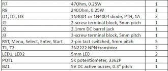
| Name | Class | Frame | Price |
| 2SK1018 | Mosfet N-channel | TO-3P | 400 rubles |
| 2N2222 | Bipolar NPN | TO-92 | 10-15 rubles |
| KT973A | Bipolar PNP | TO-126 | 25-30 rubles |
| KT816B | Bipolar PNP | KT-27 | 15 rubles |
| IRF620 | Mosfet N-channel | TO-220 | 30-40 rubles |
How to avoid 3 mistakes when selecting and installing a transistor
When selecting a bipolar transistor, you should pay attention to parameter h21. H21 is the gain of the collector current relative to the base current. If the value of this parameter for the transistor is 30, then the analogue should be selected such that the value of h21 is no less than 30.
To determine which npn or pnp transistor structure to use in the circuit, use this simple rule: if the control signal arriving at the base is negative. then type pnp is put, if positive - npn. Please note that the base signal must be of the same polarity as the supply voltage!
The relay has a high self-inductive emf value of several tens of volts when the circuit breaks. Therefore, the collector junction should be protected with a parallel diode. The diode is placed opposite the polarity of the power source: cathode to positive, anode to negative.
DANGEROUS! If this is neglected, the transistor will fail at the first switching.
Video of 12V time delay relay
Answers to the 2 most asked questions
- Question.
Are there any analogues for ne555?
Answer:
Yes very many. All are similar to each other, like two peas in a pod in terms of internal architecture. KR1006VI1 - the closest domestic analogue of ne555
- Question.
How does a relay work?
Answer:
the relay consists of an armature, electromagnets and switching elements. When a current of the required magnitude is supplied to close the contacts, the armature closes - the relay begins to pass current. When the control current decreases to the cut-off value, the armature opens to its original position due to the constant mechanical spring pressing on it - the current stops flowing.