The life of a modern person is full of electrical appliances. They give us the necessary light and warmth, convey information, make it much easier to carry out many everyday household tasks, help in construction, repairs, and when working in the garden. Neither performing home health procedures nor organizing family leisure time can be done without them. Naturally, all this equipment requires appropriate care and ability to handle it. But in this matter, scientific and technological progress comes to the aid of man.
For rational, economical operation of electrical appliances, automated control systems are widely used. They are capable of performing a lot of useful functions, including the ability to turn devices on or off exactly when required, according to algorithms specified by the owners.
Time relay
Modern control systems sometimes amaze with the breadth of their functionality. But sometimes automation devices that are simpler to design and operate are sufficient. Thus, one example of simple automatic control devices, which, by the way, have been introduced into human life for quite some time, is a time relay. What it is, what it can be used for, what types there are and on what principle they work - all this is discussed in this publication.
Types of mechanisms
The purpose of using these mechanisms is to close and open the conductor through which electric current flows. The general function is to perform some action after a certain time period. Thanks to modern modifications of devices, you can save a lot on electricity, which is why they are often used in lighting systems not only for public buildings, but also for entrances, private houses and courtyards. Device types:
- monoblock;
- modular.
Monoblock ones are built into electrical appliances. They are self-contained devices that have their own power supply inside, as well as the necessary connection inputs. This type does not have its own body. It is installed in the main device and is its element. The modular device complements electrical appliances.
According to the method of operation, the following types of time relays are found:
- mechanical with clock mechanism;
- mechanical with anchor mechanism;
- electronic;
- motor.
There are also products with pneumatic or electromagnetic retardation. The most widely used are electronic time relays. They allow you to set a timer for several days. At the same time, they have quite compact sizes and low power consumption.
Algorithms for operation of time relays, functional diagrams, symbols
What algorithms can time relays operate by?
It was already mentioned above that any relay can operate to close, open and switch contacts with the necessary control action. And the time relay provides for either a pause after such an impact, or even compliance with a certain cyclic operation.
There are many algorithms for operating time relays. The diagrams below will discuss the most commonly used ones.
In the diagrams, the top graph (blue) shows the supply voltage supplied to the relay. The bottom graph is the output voltage going from the relay to the actuator (to the load). Red arrows show the ranges of the set response delay.
One more note. Control signals for relays can be supplied in different ways.
- This may be the general power supply voltage supplied to the device. Such relays are called power-controlled.
— A separate external signal supply circuit is used for control.
The diagrams below, just for clarity, will mainly show (with one exception) the algorithms for power controlled relays. But for the second option they are basically the same.
Algorithm 1
Algorithm diagram No. 1
Time relay with switch-on delay. After turning on the power, the output signal will be transmitted to the load after the set pause T .
Algorithm 2
Algorithm diagram No. 2
The output signal in this embodiment is transmitted to the load immediately after turning on the power. But after a set interval T is interrupted.
Algorithm 3
Algorithm diagram No. 3
The load is turned on simultaneously with the supply of general power. But the shutdown is performed after a pause T from the moment the relay supply voltage is removed.
Algorithm 4
Algorithm diagram No. 4
Cyclic operation of the time relay, with a pause at the start. After supplying the supply voltage, the output signal to the load appears after interval T1. This signal is maintained for a certain set interval T2. Then an opening occurs, with a second pause T1, after which the load is turned on again for a time T2 - and so on until the supply voltage is completely removed.
Algorithm 5
Algorithm diagram No. 5
One of the options with permanently connected power and control using an external signal. When a control pulse is applied (or, conversely, when it is removed - shown in highlighted color and dotted line), the relay is activated and switches power to the load. Power is supplied for a set period T1, after which it is automatically turned off until the next control pulse arrives.
These algorithms can be called basic. And from them, as from “bricks”, much more complex circuits can be built, implemented in relays of various designs and models.
One of the most important characteristics of a time relay is the functional diagram
By the way, the graphic diagrams shown above are called relay functional diagrams, and are usually indicated on the device body or in its technical documentation. That is, when choosing the required product for certain needs, knowing how to read such diagrams, you can find a suitable model.
Below, two illustrations will demonstrate the variety of functional diagrams of time relays offered for sale. This is shown as an example only, as in reality the choice may be much wider. Please also note that some relays may have several outputs to the load, as well as several channels for receiving an external control signal.
Examples of functional diagrams of power-controlled time relays.
Functional diagrams of time relays - table A
Examples of functional diagrams of time relays with external signal control.
Functional diagrams of time relays - table B
Values of time intervals T, T1, T2, etc. most often the user can install it. True, there are time relay models in which the response time is already preset and cannot be changed. But these are devices for special purposes, usually installed in protection circuits for electrical devices and installations. Naturally, the delay value in this case is indicated in the technical description of the product.
One time relay can implement several algorithms for its operation, with a choice. And functional diagrams and contact diagrams are usually depicted on the product body.
Designations of time relay contacts on diagrams
When choosing a time relay, you must be able to understand not only the functional diagram, but also the contact layout. Usually the following accepted notations are found:
A. Contacts that operate to open the circuit.
Symbols of contactor time relays operating to open
1 — arc facing down: response delay after control voltage is applied;
2 — arc facing down: response delay after removing control voltage;
3 - two oppositely directed arcs: delays both when the control voltage is applied and when it is removed.
B. Contacts that work to close the circuit.
Symbols of contactor time relays operating on closure
The trigger conditions, of course, don’t need to be described - they are the same as in the previous example.
Principle of operation
The time relay is equipped with a contact group. It is with its help that switching on and off occurs. The controller is a coil, which is an electromagnet, or a clock mechanism. In analog and electronic devices, a quartz oscillator is used. With its help, impulses are formed that determine the passage of time. The devices operate according to the following principle:
- A signal is sent to the device.
- The required number of pulses is pre-programmed in the device.
- Once the required indicator is reached, some action occurs.
- The time counter goes back to zero, after which the whole process is repeated.
An electronic (digital) time relay replaced the analog mechanical one. Such devices are controlled using anchors, which change contacts with a certain delay. The device operates by changing the voltage across the capacitor. The design has a special unit. It operates on RC circuit. It is this element that sets time. At the required period, a command is sent to the relay. The device either closes or opens contact pairs that are included in the circuit.
Modern devices are complemented by a microcontroller, with which a person can program the device without disassembling it. This type does not require any specialized setup. It begins to function immediately after connecting to the power supply. These relays can be set to delay from 1 second to several weeks. The design includes:
- magnetic wire;
- a special non-magnetic gasket (it must be present for correct operation);
- anchor.
To slow down the switching, a short-circuited winding is often used. When electric current is applied to it, a magnetic field appears, which creates an obstacle to the increase in magnetic force. This significantly reduces the armature response time. Pneumatic devices operate thanks to a damper. The delay is controlled by an air hole, the cross-section of which can be changed.
You might be interested in the principle of operation and design of an electronic megohmmeter
The best time relays for installation in an electrical panel
Similar models have fastenings for mounting on a DIN rail. Such time relays are used when it is necessary to control not just one device, but an entire network of equipment connected to the distributor.
Orbis Astro Nova City OB178012
5
★★★★★
editorial assessment
100%
buyers recommend this product
The model is automatically adjusted to the current geographic location twice a day.
Saving settings during a power outage completely eliminates the need for regular monitoring of the relay operation. The wide backlit display makes it easy to use in low light conditions.
The minimum switching interval is 0.01 min, the permissible power for connection is 3 kW. The device has a backup battery, the resource of which is enough for 10 years of cyclic operation. Bluetooth support allows for remote control.
Advantages:
- operation accuracy;
- durability;
- convenient control;
- automatic setup;
- low power consumption.
Flaws:
- high price.
Astro Nova City is suitable for work not only indoors, but also outdoors. A reliable choice for automating lighting systems, storefront lighting or advertising signage.
Systemair MicroRex D21 Plus
5
★★★★★
editorial assessment
100%
buyers recommend this product
The model gives the user the ability to program up to 28 operating modes for turning devices on and off.
If necessary, automatic transition to winter or summer time can be set. Each program is protected from accidental changes.
The spring life is 6 years, the operating error is no more than 1 second. The copy function allows you to transfer the established cycle settings to other days. The wide monochrome display shows the time and date in digital format.
Advantages:
- simple installation;
- convenient setup;
- long service life;
- small dimensions;
Flaws:
- high price.
The Systemair MicroRex relay will be useful if you need to automate the operation of a large number of devices. It is suitable for daily and weekly programming.
DigiTOP RV-2n
4.9
★★★★★
editorial assessment
96%
buyers recommend this product
The model can operate according to a daily or weekly cycle. The user can program up to four time intervals daily. Thanks to non-volatile memory, the settings are not reset when the power is temporarily turned off.
The permissible connected power is 2.2 kW, the maximum number of starts per day is 16. The ease of use of the relay is facilitated by fully digital control, the function of displaying the current time and a 1-minute interval between turns on.
Advantages:
- saving settings;
- simple fastening;
- small dimensions;
- digital display.
Flaws:
- difficulty of initial setup.
DigiTOP RV-2n will be useful for use in a private house or apartment. An excellent choice for programming a fan, heating boiler or lighting system.
ABB AT1e
4.8
★★★★★
editorial assessment
88%
buyers recommend this product
There is a software disk on the front panel of this device. With its help, the user can easily configure the relay operation for the next 24 hours. Other controls are also located at the front, which makes it possible to change the contact state without disconnecting the load.
Rated voltage 230 volts, dimensions - 17.5x90x64 mm. The functionality of the device allows you to set up to 96 switchings with a minimum interval of 15 minutes.
The model operates stably at temperatures from -10 to +50 °C, so it can be installed in an unheated or, on the contrary, too hot room.
Advantages:
- convenient setup;
- a large number of switchings;
- compactness;
- heat resistance;
- low price.
Flaws:
- high energy consumption.
The ABB AT1e relay is designed to control electrical circuits with a repeating daily cycle. An excellent solution for artificial lighting systems for plants, heating, irrigation, etc.
Feron TM41
4.7
★★★★★
editorial assessment
85%
buyers recommend this product
Among the main features of the model are resistance to negative temperatures and a high level of permissible load - 3500 W. This makes it possible to use the device both indoors and outdoors. Its operation is programmed for a day or a week.
The number of modes is 8, the minimum switching interval is 1 minute. Once connected to the network and the cycle has been determined, the device does not require regular monitoring. The digital display and intuitive control panel will make it easier for an inexperienced owner to configure the relay.
Advantages:
- heat resistance;
- compactness;
- easy setup;
- autonomous work;
- low price.
Flaws:
- relatively small number of modes.
Feron TM41 will be an excellent purchase for a private home or cottage. With its help, you can automate the operation of household appliances or street lighting systems.
READ ALSO
9 Best Smart Plugs
Types of devices
People are often interested in how and why a time relay is used. There are many varieties of this device, and accordingly, the purposes may be different. The relays are mounted both in household networks with a voltage of 220 V and in high voltage ones. They are intended to automate the process of turning on and off electrical appliances with a certain delay.
Before purchasing, it is advisable to find out about the types of devices. In addition to the main options, there are also capacitor models. The main element in them is an electromagnetic relay. They have very low resistance, so the connection occurs via an intermediate circuit. Due to their low cost and ease of operation, capacitor types have gained immense popularity among photographers and radio amateurs.
Generating apparatuses are made of a generator that sends special impulses. The counter is triggered when the number of pulses reaches the required value. The delay can be set up to several hours.
Static devices are electrical devices that have a delayed action. Work on their development was carried out in order to replace mechanical and analog relays.
During Soviet times, transistor devices were produced. They had their advantages when compared with mechanical models. Control could be carried out remotely. Transistor relays were compact in size and also had less error.
After the transistor, integrated circuits began to be used. With the help of such devices it became possible to reduce the dimensions of the structure. Modern models contain special microcontrollers. Their main element is a bimetallic plate. The downside is that the operation of the device may be affected by the ambient temperature. Bimetallic strips are used in common household appliances:
- refrigerator;
- electric kettle;
- iron;
- fluorescent lamps.
Mercury modifications can also be found. The basis for their work is the natural flow of metal through a small hole. The flask is divided into two parts and connected by a tube with a small cross-section. When triggered, it turns over.
Electromagnetic devices
Devices operating on the principle of an electromagnetic field are often made only for operation in networks powered by direct current. The time range ranges from 0.07 to 0.11 seconds to complete the circuit. When turning off electrical appliances, this value can range from 0.5 to 1.4 seconds. A design feature is that such relays have two windings at once. One of them is made like a copper ring and is intended for a short-circuited circuit.
During operation of the main winding, an increase in magnetic flux can be observed. Due to this, an electric current appears in a short-circuited circuit, which leads to a decrease in the growth of the magnetic field in the first element. This principle determines the emergence of temporary indicators of the movement of the actuator. To put it simply, there is a delay to turn on.
If no current is supplied to the main winding circuit, then the magnetic field on the second element will still remain active for a certain period of time. This is due to the effect of inductance. During this period, the relay is in working condition.
You might be interested in Features of assigning group 4 for electrical safety
Pneumatic devices
Devices operating on the principle of pneumatic systems are exclusive devices. Such devices include a pneumatic mechanism that performs the task of deceleration. The time delay in these relays is adjusted by changing the inlet diameter of the tube through which air is drawn. To control this indicator, an adjusting screw is provided in the design.
On pneumatic relays, a time delay can be set in the standard range from 1 to 60 seconds. There are also devices that almost double this value. But in practice they have shown that they have a fairly high error (about 10%). Operation occurs with approximately the same time error.
Watch modifications
A clock relay is often used in electrical applications. This device is often used as an additional element in the protective structures of circuit breakers in networks with voltages up to 10,000 volts. The delay can be set from 0.1 to 20 seconds.
Clock relays operate due to the action of a spring. It is cocked through a mechanical drive of an electric magnet. The position of the contact groups of this device changes after a period of time has passed. It is assigned using a scale installed on the device.
The speed of movement of the temporary mechanism directly depends on the value of the current that is passed through the electromagnet winding. Thanks to this, you can configure the device so that it plays a protective role. A distinctive feature of this protection is that it does not depend in any way on the ambient temperature. Such devices are the easiest to repair.
Electronic models
In recent years, almost everywhere where it is possible to use a relay that operates after a certain time, electronic mechanisms are used. Such devices have certain advantages:
- small sizes;
- minimum error during operation;
- Setting up the device is very simple and convenient;
- all information is displayed on the screen.
Electronic analogues of time switches often operate thanks to digital counters. Most modern devices have built-in high-performance microprocessors.
There are special keys on the body that are used to configure the device and set the required time frame. The adjustable range often has very wide limits. Thanks to this, you can set it to turn on or off even for several weeks.
Weekly timer
A relay that makes it possible to automatically turn on or off electrical appliances fits perfectly into circuits that involve controlling various types of devices. The weekly timer allows you to perform switching tasks at any time interval within seven days. With this device you can:
- turn lights on and off at certain times;
- manage the launch of any technological equipment;
- start or disable the functioning of security systems.
The device is very compact and has several functional buttons on the side panel of the case. If you use the system keyboard, you can easily program the device.
You can enter the control panel by holding down the key with the P symbol on it. It is also possible to reset all settings to factory settings using the Reset button. Setting time parameters is done using separate keys indicating seconds, minutes, hours, etc.
During connection, you can select the control mode. There are only two of them - manual and automatic. Thanks to the liquid crystal display, making all settings is easy and convenient.
The best socket time relays
Models of this type are used to control the operation of household electrical appliances. They are connected to the network via a 220 V outlet, have compact dimensions and low cost.
EKF SAT-20p
5
★★★★★
editorial assessment
100%
buyers recommend this product
The model's body can be rotated 180 degrees for convenient plugging into a hard-to-reach outlet. Protective curtains protect the phases from contamination or mechanical impact, which increases the safety of using the relay.
The maximum load power is 3600 W, the timing accuracy is 15 sec/day. The built-in battery ensures that the settings are saved. The ease of use of the device is facilitated by the presence of a wide display and eight control buttons marked in Cyrillic.
Advantages:
- compactness;
- low power consumption;
- easy installation;
- ease of setup;
- long term programming.
Flaws:
- high price.
EKF SAT-20p is suitable for controlling the operation of household appliances, lighting, aquarium equipment, etc. An economical solution for use in a private house or apartment.
Robiton EL-04
4.9
★★★★★
editorial assessment
95%
buyers recommend this product
The model received a large screen with bright LED backlighting. An electronic timer and electric current indicator make the device easier to use.
The user can select the time display mode and use the random activation function to create a “presence effect”.
The maximum load power is 3600 W, the installation time interval is from 1 minute. The owner has access to up to 10 independent operating programs. The countdown is adjustable from 0 to 100 hours.
Advantages:
- easy setup;
- display backlight;
- long service life.
- operation accuracy;
- frost resistance.
Flaws:
- large dimensions.
Robiton EL-04 can be used to provide scheduled lighting for aquariums, turn on a night light in the evening, and automate the operation of an air conditioner.
TDM Electric SQ1506-0002 TRE-01
4.9
★★★★★
editorial assessment
94%
buyers recommend this product
The device body is made of non-flammable plastic. A digital display and a set of buttons with symbols in Russian provide easy programming of modes.
The relay is equipped with a battery that guarantees data retention for 100 hours after a power failure.
The maximum load power is 3500 W, the permissible current is 16 A. The device supports weekly and daily cycles.
It operates stably at temperatures from -10 to +40 °C. Additional features include time delay and countdown functions.
Advantages:
- ease of control;
- built-in battery;
- heat resistance;
- low error;
- compactness.
Flaws:
- difficulty of initial setup.
TDM Electric TRE-01 is used to automate the control of household appliances. With its help, it is convenient to control the operation of a heater, air conditioner, TV and other similar equipment.
READ ALSO
14 best surge protectors
REV 67073 1
4.8
★★★★★
editorial assessment
87%
buyers recommend this product
The relay makes it possible to program up to 16 operating modes. The setup is done once, the cycle is repeated automatically every day until the next schedule change. The maximum number of starts per day is 10, per week - 140.
The built-in battery prevents settings from being reset after a power outage. A random number sensor can be used to involuntarily turn lights on and off at different intervals. This ensures the visibility of the owners’ presence in the house.
Advantages:
- countdown function;
- display of exact time;
- low energy consumption;
- built-in battery;
- small dimensions.
Flaws:
- flimsy body.
REV 67073 will be an excellent purchase for the garden. The relay will help turn on the heating system before arrival or scare away burglars while the owners are away.
Setting up electromechanical devices
Industrial equipment and household modules can often be supplemented with electromechanical devices. Their design is such that control is carried out using potentiometers. A special potentiometer rod is located in front of the housing. It is made to fit a flat screwdriver. Around this element there is a scale with values.
You might be interested in How the Hall effect is used: principles of the phenomenon and methods of application
The slot acts as a kind of pointer that changes its direction during rotation. To set the required time indicator, you should install the slot for the screwdriver opposite the required value.
The most common example of devices of this type is the NTE8 electromechanical relay. It is used to control ventilation systems, artificial lighting and heating modules.
Types of device
The main types of time relays depending on the technologies used in their design:
- The most reliable and used for a long time are clock or anchor ones. Their operation is ensured by a spring mechanism, wound by hand or automatically when voltage is applied to the device. A distinctive feature of such a device is the presence of a mechanical superstructure scale, by setting the values on which, the time and period of switching on and interrupting the current line for the consumer are set.
Clock relay device
- Motor. In some ways, such relays are similar to anchor relays, only to move the clock, it is not a spring that is used, but a small electric motor. The mechanism of the device operates from it - it ensures the rotation of all gears of the gearbox, which move the closing contacts to the “on” or “disconnected” state. The response parameters themselves are set manually using special clamps.
Simple, motorized time relay
- Pneumatic or hydraulic. They are mainly used in production, to control machines. The slowing down of the switching mechanism is ensured by a special air or liquid damper, which slows down the pusher in the electromagnet, which in turn connects the contacts. The response period depends on the volume of the working fluid in the limiting chamber. When, with the electromagnet turned on, the pusher presses on the membrane, it does not bend immediately - air or liquid must first come out of the damper chamber underneath it, and only then will it reach the finish line and connect the terminals. By adjusting the flow rate of the working fluid, the time intervals for actuation of pneumatic or hydraulic relays are set.
Pneumatic relay device
- Electromagnetic. Already closer to modern and still often used time relays. Their operating principle is an electromagnet, which, when the required field strength is applied to the magnetic core, connects it to the power supply contacts of the client device. The operation pause is provided by an additional coil (sleeve) placed on the same magnetic armature, but with reverse current flow. The operating time of such a relay is based on the effect of residual magnetism of the core, which continues to create a field for some time after the main winding is turned off.
Electromagnetic relay device
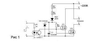
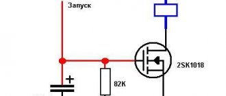
- Electronic. Conventionally, they are all built on the charging period of the capacitor, the slowdown of which is ensured by the characteristics of the load resistor. When the capacitor reaches full capacity, it stops passing current through itself, which makes it possible for the semiconductor or lamp element to open, which then turns on or breaks the power supply to the client device. After the capacitor is discharged, a reverse cutoff of the consumer occurs. Devices based on such elements are quite easy to recognize - on their surface there are regulators, made either in the form of slots for screwdrivers, or handles, which control the resistance parameters of the resistors in the circuit.
Simple electronic relay circuit
- Brain teaser. Time relays with such a base use microcircuits for their operation, which contain logical adders that count time depending on the number of clock cycles passed by the master oscillator. At the moment when the set values are reached, the “processor” of the device sends a signal to the executive circuit, which in turn connects the power to the consuming part. After the number of cycles reaches the second value specified by the device, the line is interrupted. This class of equipment is easy to recognize by the presence of digital displays and many keys with which the required parameters are programmed.
Simple logic relay circuit
Adjusting digital equipment
The use of devices with mechanical settings can be explained using the example of the REV Ritter timer. It plugs into the most common household outlet. With the help of this device, control of any home appliance is monitored within the required time frame. It is configured as follows:
- All elements around the disk are raised.
- Only elements that are opposite the required time value are omitted.
- The dial is turned to set the current time.
For example, if you omit segments with numbers 15 and 21 on the disk, then after the device starts operating, the power will be connected at 15 o’clock, and the circuit will break at 21 o’clock. The design of the REV Ritter mechanism involves the organization of 48 periods in a full day.
The equipment also has the ability to externally connect the load. To enable this function, there is a separate button located on the side of the case. If you click on it, power will be supplied to the device without taking into account the settings.
Adjusting instruments with a digital scale
Setting up devices of this type is illustrated using the example of a timer with a digital scale of the “REV Ritter” brand, plugged into a regular power outlet. The period of validity of its temporary delay is, as a rule, limited to one day, which is quite enough for domestic conditions. Instructions for setting up such a relay include the following points:
- Plug the device into a power outlet.
- Move up all the adjusting elements (segments) aligned around the circumference of the adjustment disk.
- Move down only those that correspond to the set time.
- The center disk indicator is set to the current time.
If the segments located between the numbers 18 and 20 are shifted down, the desired load will turn on after the 18-hour interval and turn off after two hours. The design of such a semi-automatic device provides the ability to organize up to 48 work cycles (on and off) within two calendar days.
Connection to control circuit
Connecting the device must be done taking into account all the conditions that are specified in the technical data sheet of the device. Often it needs to be mounted vertically. The maximum permissible deviations from the vertical should not exceed 10 degrees. Temperatures should also be taken into account. Installation and operation of the temporary control device must be carried out at temperatures from -20 to +50 °C.
The humidity level in the room where the time relay will be used should not exceed 80%. The electrical circuit to which the timer is installed should be disconnected from the power supply for this period.
Any design of the device requires the presence of a technical passport. It contains a detailed connection diagram. In digital and electronic-mechanical products, the circuit is also printed on their body. The standard connection method is performed in the following sequence:
- Connecting the power cable to the terminals.
- The core with the phase must be passed through the machine.
- The phase is connected to the load in real life.
This scheme works for all types of devices. Depending on the design of the device, the number of contact pairs may vary.
Types of relays
Block models
According to the method of connection to the existing electrical network, all relay devices are divided into the following classes:
- block type devices;
- switches built directly into an electronic circuit;
- modular designs.
Block-type devices are made in the form of a monolithic adapter that is plugged directly into the outlet. Their contacts are directly connected to the phase and zero of the switched circuit. Embedded samples do not require a third-party power source, as they work as part of complex electronic circuits.
Modular devices
Modular time relays are mounted on a DIN rail in the distribution cabinet and connected to the adjacent zero and phase bus. In accordance with the design features of a particular actuator, all known relay samples have the following designs:
- electromagnetic type;
- devices made on the basis of an electronic circuit;
- pneumatic and electromechanical devices similar to winding mechanisms (the latter in appearance resemble watches).
In private practice, electronic and electromagnetic devices are widely used, which is explained by the simplicity of their design and relatively low cost.
Digital load disconnect delay relay
Based on the type of mechanism that provides the time delay, these devices are divided into the following classes:
- with electromagnetic retardation;
- pneumatic (compressor);
- with a clock (anchor) retarding mechanism;
- motor systems;
- electronic-mechanical analog devices.
Each of the listed samples differs from analogues in its characteristics and is used in specific conditions at the discretion of the user. Modular structures installed on a DIN rail can be used as a 220 Volt temporary relay for lighting indoor spaces.
Settings
Installing a socket with a timer, as a rule, does not cause difficulties. Therefore, let's move straight to the setup process.
For mechanical model:
- Study the instructions and capabilities of the device in terms of time range.
- Set the mark on the socket to the current time. Rotate the regulator carefully to avoid accidentally damaging it.
- Set the time when the socket should operate (apply or remove voltage).
- Connect the equipment to the plug.
Advantages and disadvantages
Each type of relay has its pros and cons:
- Sentinels or anchors. Their big advantage is their almost complete independence from third-party power supply and truly iron-clad reliability. The downside is that sooner or later, if left unattended, the mechanism may malfunction or fail altogether. Again, the connection of contacts over time in such devices occurs directly, which means there is a chance of a spark occurring. Which, in turn, limits the application niches of a mechanical timer - in any fire-hazardous environment, this factor creates many problems.
Anchor time relay EV-142
- Motor. Such time relays have the advantages of mechanical ones, but also the same disadvantages - eventual (albeit not quick) failure and spark connections.
Motor time relay RVT-1200
- Pneumatic or hydraulic. They are reliable, but they are large in size, which is due to the volume of the damper chamber. Among other things, the accuracy of setting time intervals on them is relatively low and requires the participation of a trained specialist. That’s why such relays are used only in industries that have their own staff of adjusters.
Pneumatic time relay RVP-72
- Electromagnetic. Despite the simplicity of their design, they have a significant drawback - the accuracy of adjustment to time intervals is very difficult and varies in each device, regardless of the number of turns of the control screws. That is, in other words, by turning the screw ten times and setting the time on one device, turning the same regulator ten times on another cannot achieve the same response period as the previous one.
Modern electromagnetic relay
- Electronic. Currently, such devices are replacing all previous models. They are practically devoid of disadvantages, are relatively accurate in setting, and the line connection in such devices occurs using a non-contact method. The only disadvantage noted by users of this type of timers is the ease of setting delay periods.
Example of a simple electronic relay
- Brain teaser. They represent the development of electronic options, with better display, more convenient control, as well as the possibility of using them as parts of a “smart home”. The time scale on logical devices is limited only by the depth of the embedded program. An additional plus is that the logical elements they contain can be triggered not only by time intervals, but also by external control pulses-signals from sensors or controllers. The only negative so far is the price - it is a little higher than for just electronic ones. Setting up such time relays is already called programming.
Example of a programmable time relay