The idea of controlling lighting fixtures using touch switches is not new; similar switches or light switches were produced back in the last century. But the dimensions of such devices were significantly larger than standard ones, which caused problems during installation. It is also worth noting that the cost of the first touch switches was quite high; naturally, this did not contribute to their popularity. With the development of technology, the situation has changed radically, and today capacitive, infrared and remote switches are in stable demand.
Design and operating principle
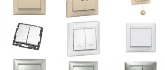
Despite the variety of models of touch communicators, most of them have a standard design consisting of the following elements:
- Housing made of heat-resistant plastic (see A in Fig. 1). The dimensions of the structure allow installation in a typical mounting location of a conventional switch.
- Electronic unit (B), it includes a power adapter and a semiconductor switch control circuit.
- Board with capacitive sensors (C).
- The front panel (D), as a rule, is made of quartz glass; budget models may use other materials.
Fig. 1. Legrand six-key touch wall switch
Now we’ll tell you how such devices work. The electronic unit monitors the state of the sensor. When you touch a certain place on the front panel of the switch with your hand (it is marked accordingly), the capacitance of the sensor changes. The electronic unit detects this and changes the state of the contactless semiconductor switch, which opens or closes the electrical circuit.
Adjusting the sensitivity of the capacitive sensor:
The sensitivity of the “TTP223” module depends on the size of the sensor and the capacitor – C3 (not soldered on the board), the place for which is located on the board between pin 3 of the microcircuit and the common wire (GND).
There are several methods you can use to adjust the sensitivity of the “TTP223”:
- to increase it, you need to increase the size of the contact pad of the sensor; to do this, using a hole on the pad, a short wire is soldered to it, which connects to the new enlarged contact pad.
- also, to increase sensitivity, you can reduce the thickness of the housing wall behind which the sensor will be located
- Another way to increase sensitivity is not to use capacitor C3 (when it is not present, the sensitivity is maximum, when C3 is installed = 50 picofarads - minimum). C3 can be used in the range from 0 to 50 pF.
Scope of application
Initially, this type of switch was planned to be used to turn on/off lighting, but the design turned out to be so successful that the scope of its application has expanded significantly. Today, most modern household appliances have touch controls; examples include kitchen stoves, hoods, microwaves, etc.
Kitchen hood Cata Midas 900
The only limitation on connecting to touch switches is the power of the equipment; its permissible parameters are indicated in the device passport.
Additional functionality
Modern technical base has made it possible to install microcontrollers in the electronic control unit of a touch switch, which has significantly expanded the functionality of switches and allowed them to fit into the concept of a smart home. Such switches can be controlled by voice, infrared or radio remote control, smartphone via WI-FI or a programmable timer.
The touch switch can be connected to the smart home system and controlled using a mobile phone
Touch switches can be used in conjunction with sensors that respond to motion or light levels. In the first case, such devices turn on a lamp, table lamp or other lighting fixtures when someone enters a room, such as a bathroom. With the second implementation option, the light will turn on at a low light level.
Sesoo triple touch switch and motion sensors
Some manufacturers, for example, Livolо, produce touch switches with a dimmer function or that control combined sockets, to which almost any household appliance can be connected.
Livolo touch switch with socket block
Device options and capabilities
Switches with a timer clearly deserve special consideration.
There are traditional characteristics here, such as:
- silent operation;
- interesting design;
- safe use.
In addition to all this, another useful feature is added - a built-in timer. With its help, the user is able to control the switch programmatically. For example, set on and off times in a certain time range.
A unique option for developing a switch with integrated timer functionality. With the help of such devices, it is possible to control lighting at a strictly specified time. Electricity savings are obvious
As a rule, such devices have not only a timer, but also an accessory of another kind - for example, an acoustic sensor.
In this embodiment, the device works as a motion or noise controller. It is enough to raise your voice or clap your palms and the lamps in the apartment will light up with a bright light.
By the way, in case the brightness is too high, there is another functionality - dimmer adjustment. Touch-type switches equipped with a dimmer allow you to control the light intensity.
Modification of touch devices – acoustic switch. It operates according to a slightly different method, but is also a device that supports technologies for using sensors. In this case, the sensor element is a sensitive microphone
True, there is one caveat for such developments. Dimmers, as a rule, do not support the use of fluorescent and LED lamps in luminaires. But eliminating this shortcoming is most likely a matter of time.
Read more about the types of “smart” light switches in this article.
Advantages of capacitive switches
Speaking about the advantages of this type of switches, the following qualities should be noted:
- Long service life. This is greatly facilitated by the absence of moving parts and contact groups.
- Compatible with all types of lighting fixtures. Models with dimming are available for LED strips and energy-saving lamps, if they have such an option. In addition, switching of any circuits that meet the operating conditions of the switches is allowed
- Availability of additional functions.
- Possibility of integration into the Smart Home system.
- Large selection of colors and designs.
Switches “Hares” model range Kopou - No mechanical contacts.
- The touch sensor can be installed in a standard “glass” for a hidden wiring switch.
Now briefly about the shortcomings. First of all, it is necessary to note the difference in cost with conventional mechanical switches, but it has become significantly less than 10-20 years ago. The price of inexpensive Chinese touchscreen models today is much cheaper than mechanical switches from well-known brands, such as GTS or Electronics.
Sometimes LED lamps connected to touch switches flicker. This may be due to both the low quality of the lighting sources themselves and the low-cost switch models. The problem can be resolved in two ways:
- Use products from well-known brands (Jazzway, Panasonic, Sapphire, Funry, LightaLight, Tronic, Sesso, etc.).
- Connect a 0.1 uF 630 V capacitor in parallel with the LED lamp.
Electric field indicator
An electric field indicator of the simplest type can be assembled according to the circuits shown in Fig. 8 and 11 [Rl 9/98-16].
The inputs of unused inverters/SHOG7 microcircuits must be connected to a common wire or power bus (Fig. 8). When the indicator approaches the power cable, in the first circuit, sound signals are generated, reproduced by a piezoceramic emitter; in the second circuit, the device responds to an alternating electric field with sound signals.
Rice. 8. Electrical wiring finder diagram.
Rice. 11. Electric field indicator circuit.
Connection
The installation of touch switches is practically no different from the installation of conventional built-in and surface-mounted mechanical switches. You can read more about this process on the pages of our website. Let us remind you how to do this using the example of the kg020gs model from the manufacturer FD Electronics.
Connection algorithm:
- Remove the glass panel (see A, Fig. 7). This can be done conveniently using a thin slotted screwdriver.
- We connect the installation wires (B in Fig. 7), according to the diagram given in the passport.
Figure 7. First and second connection stages - We screw the board with touch contacts (A Fig. 8).
- We connect the panel with the button marking (B in Fig. 8).
Figure 8. Second and third stages of connection
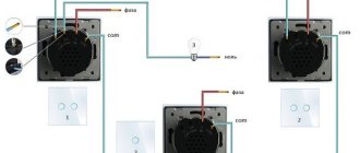
Some manufacturers, for example, Livolo, produce pass-through switches for 220 V (their connection diagram is shown in Fig. 9). With their help, you can control lighting from several places.
Figure 9. A clear example of how to connect several pass-through touch contact panels
Each of these switches controls the lighting in the room from different locations. The concept involves using a main switch and one auxiliary (or more). On the main devices there are three terminals, the phase is connected to one, the zero is connected to the other, and the control conductor is connected to the third. Accordingly, such contacts are marked as: L – phase, N – zero and Com – control wire. Assistive devices
Secondary switches are connected through two terminals: N – zero and Com – control contact. Labeling may vary from manufacturer to manufacturer, so it makes sense to study the instructions. An example is the connection diagram for the electronic dimmer et0802193e, or its analogue tt6061a, which can be controlled with a light touch of your hand.
Touch dimmer connection diagram et0802193e
Self-assembly of touch communicators
The main disadvantage of smart switches is the price. Having basic knowledge of electrical engineering will help you assemble a homemade product. Home craftsmen use 3 main assembly options.
The transistor touch button circuit is the simplest. To implement it, you will need a breadboard on which series-connected KT315 transistors and an electromechanical relay are mounted, in parallel with which a protective diode must be installed. The sensor will be a wire from the base of the transistor connected to the network. The circuit can be complicated by adding an optocoupler and a trigger (NE555 timer or K561TM2 microcircuit) in front of the relay. This modification will allow the network to record the command.
You can assemble an infrared touch switch with your own hands by adding a rectangular pulse generator to the circuit. An infrared flashing LED will help to increase the current from the generator. The time interval is set on the chip. It determines how long after the signal stops the light will turn off. When the reflection of the beam hits the photodetector, the K561IE20 or CD4040 counter will display one and the circuit will close. If there is no signal at all pins, logical zero, no voltage is supplied, and the control transistor does not pass current.
Infrared switch circuit
Industrial touch switches can be modified and the sensitivity area can be expanded. Under the cover you need to find a capacitive element and solder a thin wire to it. Then lay the conductor in increasing rings until the entire perimeter is filled. Replace the protective panel.
The switches are adapted not only for lamps, but also as a doorbell, curtain drawer, etc. All parts can be purchased on radio markets or Chinese Internet platforms at a budget price.
Selecting a touch light switch
Before purchasing a device, you need to determine its functionality. To do this, the following criteria must be taken into account:
- Power of connected equipment and its connection diagram.
- Execution corresponding to the type of wiring.
- Operating conditions (if installation is planned in the bathroom, then a device with moisture protection is selected).
- Possibility of remote control (remote control or smartphone).
- Compliance of the design with the interior of the room, etc.
Having decided on the main tasks, you can begin to select a manufacturer. Naturally, you should give preference to well-known brands whose products are reliable. But at the same time, it is necessary to take into account the presence in the model range of switches of devices with the necessary functions. For example, Delumo has devices controlled by a radio remote control, and Sonoff specializes in Wi-Fi devices, Capsens Domuns Line lamps are “tailored” only for their touch switches, etc. There can be many nuances, so we recommend that you study the various options in detail.
Based on practical experience, in addition to well-known brands such as Legrand, we can recommend Vento Electric, Wemmon, Fanri, Merten, CGSS, Steu, Schneider, Ariston, etc.
MakeGood Classic wireless touch switch with remote control and backlight
We recommend monitoring online reviews where ratings of the best manufacturers are published. Selection criteria are made both by the model range of manufacturers, taking into account functionality and cost, and by other indicators.
Conclusions and useful video on the topic
This review allows you to take a closer look at light switches, which are quickly gaining popularity in society.
Touch switches marked by the Livolo product brand - what these designs are and how attractive they are to the end user. A video guide to the new type of switches will help you get answers to the questions:
Concluding the topic of touch switches, it is worth noting the active development in the development and production of switches for household and industrial use.
Light switches, seemingly the simplest designs, are so advanced that now you can control the light with a voice code phrase and at the same time receive complete information about the state of the atmosphere inside the room.
Do you have anything to add or have questions about assembling the touch switch? You can leave comments on the publication, participate in discussions and share your own experience of using such devices. The contact form is located in the lower block.
Refinement of standard devices
Many people are not happy that the touch zone on the panel is quite small, and to record a signal you need to touch it in the indicated place. Let's give an example of how you can increase the area of indirect surface contact.
Increasing the sensor sensitivity area
You should take the wire and carefully solder it to the place where the signal is supplied from the sensor on the touch board (for this you need to study the circuit diagram of the device). The connected wire is laid around the perimeter of the housing. As a result, such a frame will make it possible to trigger the sensor when touching the front panel without amplifying the signal level.
It should be noted that such an improvement will void the manufacturer's warranty.
Pros and cons of touch buttons
The advantages of touch buttons can be listed for a long time. Let's focus on the main ones:
- durability - the service life is actually determined by the integrity of the printed circuit board and the operating time of the button event handler;
- increased protection from external influences - touch buttons are much easier to protect from dust, moisture, oil;
- vandal resistance - there is nothing to burn or break out;
- ability to work in low light conditions - backlighting of a touch button is easier to implement than a regular one [9].
However, the advantages are somewhat offset by the somewhat greater complexity of touch buttons - a number of requirements arise for the layout of the printed circuit board, the shape of touch contacts, and the processing of signals from the button. The listed reasons lead to increased costs at the development stage - the appearance of additional circuit elements (and, as a result, an increase in power consumption), preparation of the printed circuit board layout (calculation of the shape and relative position of the electrodes), software (additional time for developing and debugging the project), in some cases - preliminary prototyping of the product.
DIY touch switch
For those who like to work with a soldering iron, we can recommend several circuits of touch switches that will be easy to assemble with your own hands. Let's start with a simple field-effect transistor circuit, this is exactly the principle that was laid down in the first sensor devices.
Touch switch on a field-effect transistor
Designations:
- Resistances: R1 - 10..15 kOhm (must be selected for sensor response), R2 - 3...5 MOhm.
- Capacitors: C1 – 1000 pF (suppresses false triggering), C2 – 33.0 µF x 50 volts, C3 – 470 µF x 50 V.
- Transistor VT1 – KP 501A.
- Relay K1 can be used of any type whose operating current does not exceed 150.0 mA.
The circuit is powered from a source with a voltage of 12…24 V.
Now let's look at an option based on the NE555 asynchronous RS trigger. The device diagram is shown below.
Touch switch on NE555 chip
Designations:
- Resistors: R1 – 1.0 MOhm, R2 – 1.0 MOhm, R3 – 1.0 kOhm.
- Capacitors: C1 and C2 – 15 nF, C3 – 10 nF, C4 – 0.1 µF, C5 – 100.0 µF x 25 V.
- Diodes: D1-D2 – 1N4001, D3 – standard indicator LED.
- Microcircuit - NE555,
- The relay is the same as in the previous electrical circuit.
The above diagram does not need to be configured.
Concluding the topic of homemade sensor devices, we should mention the Ardunio system. On this platform, you can assemble a switching device that can be easily integrated into a Smart Home. In addition, such a device can be easily configured to operate independently, in accordance with a given program.
Compact touch sensor for the Ardunio system
In addition, the system allows you to create several profiles for specific tasks. However, this will require programming skills. You can get more detailed information about the Ardunio platform on our website.
Note that in the above circuits, a power source with a voltage of 12-24 V is required to power the control circuit. For this purpose, it is best to use switching power supplies. The electronic balance of LED and energy-saving lamps is ideal as such. Detailed information on this topic can also be found on our website.
Development of a Z-Wave touch switch on a battery with glowing buttons
For the second year, I have been developing my unique Z-Wave switch with touch buttons, which will satisfy me in terms of functionality, design and manufacturing cost.
From the very beginning, the goal was to make the 4-button switch on a 80x80 mm battery as thin as possible; the touch buttons should be large and light up entirely when touched, and not just a small circle, like everyone else. The result is a stylish, thin switch that can control any smart home device.
During development, I solved many problems in circuit design, case design and choice of materials. Particularly interesting is the creation of the touch button itself, which lights up entirely, but let’s talk about everything in order.
- Functional
- Case design
- PCB design
- Study of light diffusers
- Selection of diffuser materials
- Usage
Video of the touch switch at the end.
Functional
The following switch capabilities were required:
- Turn on/off the light
- Adjust lighting brightness
4 buttons control 2 lighting groups.
The upper buttons, when held, smoothly increase the brightness, and when pressed briefly, turn on the light. The lower buttons, when held, smoothly reduce the brightness, and when pressed briefly, turn off the light. TODO
Make each button work in switching mode, press - on, press - off. This will allow you to control 4 lighting groups.
Case design
I liked the idea with 4 large touch buttons from Basalte, and I decided to develop it in my own direction.
Rice. 1 – KNX switch Basalte
I wanted the entire button to light up when touched, rather than a separate LED. Therefore, the case is a narrow frame with cutouts for 4 touch buttons. Locks for attaching the back cover and recesses for installing magnets have been thought out. The mounting plate is glued to the wall with double-sided adhesive tape and the switch itself is already attached to it using magnets. It is convenient to use the switch as a portable remote control and conveniently charge the battery.
Rice. 2 — Touch switch housing
All body parts were designed in Blender and 3D printed using white ABS plastic.
Rice. 3 — Development of the touch switch housing in Blender
PCB design
The PCB is designed by Proteus. This is the second version, it uses one TTP224 sensor chip for 4 channels. The first version used 4 pieces. single-channel TTP223, there is no difference in operation, but when using TTP224 there are fewer components to solder.
Rice. 4 — Development of a printed circuit board for a touch switch in Proteus
The main components on the board are:
- Z-Wave radio chip
- Robiton 800mAh battery
- 3.3V Step-Up/Step-Down Voltage Regulator S7V8F3
- Battery charging chip TP4056
- Switching power supply from battery to USB
- Calibration button
- TTP224 touch button chip
The Z-Wave chip operates in the range of 2.7V - 3.6V, the battery produces up to 4.7V, so I used a 3.3V Pololu S7V8F3 buck-boost converter. To charge the battery, I used a cheap and well-known TP4056 microcircuit; the charge current was set to half the battery capacity of 400 mA. When charging is connected, the device's power switches to USB and the battery is quietly charged; the power switching circuit is implemented on a single transistor and diode. When pressed, the button resets the power supply to the regulator and the entire circuit reboots; this is necessary for calibrating the TTP224. On the front of the board there are 4 pads of touch buttons measuring 40x40 mm and 4 LEDs. The production was ordered from Seeedstudio, I am very pleased with the quality and price.
Rice. 5 - Touch switch board
The most important component in a touch switch is the touch button controller. I tested 3 controllers and each one had both pros and cons. Results of testing 3 touch button controllers:
TTP224
Pros:
Cheap, the PCB may have sensor pads on one side and other components on the reverse side, but this greatly reduces sensitivity. Output signal setting: high/low level, button mode setting: switching/on. 4 channels.
Minuses:
If there are tracks on the back of the touch pad, it does not work well through plexiglass thicker than 3 mm, and even worse if a film is glued to the glass; it does not respond to a slight touch, only pressing with the entire pad of the finger, even with the maximum sensitivity configured (Cs = 1pF, range 0 -50pF, the lower, the more sensitive).
Rice. 6 - TTP224 on the finished board
AT42QT1011
Pros:
Reacts to a slight touch through 3 mm (or more) plexiglass, if you set the sensitivity to a medium level (Cs = 22nF, range 2-50nF, the higher, the more sensitive). Automatically adjusts to glass thickness.
Minuses:
There should be no tracks, no power, or ground under the touch pad, otherwise sensitivity will decrease. Output is only high level. 1 channel only.
Rice. 7 - Test board AT42QT1011
MTCH105
Pros:
Reacts to slight touches through 3 mm (or more) plexiglass. Interference protection by ground around and under the sensor area, automatically adjusts to glass thickness. 5 channels.
Minuses:
It takes a long time to respond to pressure and takes a long time to understand that the finger has been released, about 0.5 seconds. If you hold your finger on the sensor pad, then after 9 seconds the LED turns off and calibration occurs. The sensor pad must be covered with earth on all sides, including under the pad, otherwise it will trigger at any point of contact with the PCB.
Rice. 8 - MTCH105 on a development board
I chose TTP224 (4 channels) because all components can be placed on one PCB on one side, and sensor pads on the other side. I sacrificed sensitivity, after 3 mm the plexiglass is triggered if you touch the whole thing with the pad of your finger, although this can be interpreted as protection against accidental touching :). If there are no tracks under the sensor pad, it reacts through 4 mm plexiglass at the slightest touch.
TODO
Make a touch switch with two textolites, the first for touch pads, the second for all components. Add a vibration motor and a buzzer. Implement a dim backlight function when the built-in motion sensor is triggered.
Study of light diffusers
The task was to uniformly illuminate a 40x40mm area that the finger touches.
Due to limitations in the size of the case, it was possible to cram only one LED for each pad. I studied the design of several touch switches: Livolo, Vitrum, HTTM touch button. Each took a different approach to dispersing light evenly.
Vitrum
Italian Z-Wave switch with expensive decorative glass. The reflector-diffuser is implemented as follows: a rim is painted on transparent plexiglass with reflective paint, illuminated from the side by one LED. On the LED side, less paint is applied, thereby achieving a uniform glow throughout the entire rim. Decorative glass is installed on top.
Rice. 9 — Drawing of a reflective rim on plexiglass
Livolo
Budget Chinese touch switch. There are 2 LEDs on the board: red and blue, the LEDs shine inside the cloudy translucent plastic, due to frequent refractions of light inside, a uniform glow of the entire surface is obtained, reflective paint is applied to the PCB.
Rice. 10 — Touch part of the Livolo switch
HTTM - HelTec Touch Model
Ready sensor module with Noname chip. The reflector-diffuser consists of 3 parts: textolite with a tinned platform, plexiglass for end lighting with many micropits, and a white cloudy film.
Rice. 10 — Disassembled HTTM sensor module
Selection of diffuser materials
Diffuser made of frosted plexiglass.
Ordinary transparent 3 mm plexiglass was treated with fine sandpaper on both sides to give it a matte finish. Such plexiglass evenly scatters light over the entire surface. The thickness of the material allows you to comfortably work with any sensor chip. But small scratches are visible on the surface, which affects the aesthetic appearance.
Rice. 11 — Frosted plexiglass
Plexiglas diffuser for edge lighting (LGP) and milky plexiglass
I used 2 different plexiglass with a thickness of 2 mm, a sandwich of two elements turned out to be 4 mm. The lower plexiglass for edge lighting, thanks to the applied white dots, evenly scatters light over the entire surface. The top milky plexiglass gives a soft glow and a beautiful appearance, while the brightness is noticeably lower and the weight of the switch increases.
Rice. 12 - Plexiglas for edge lighting and opal plexiglass
Lightbox panel from Ledison
The Russian company Ledison provided for testing a lightbox panel consisting of 3 components: a reflective substrate, a special light-diffusing 3 mm plexiglass (it looks transparent, but the grainy structure is visible inside), and a transparent protective film. I replaced the top film with matte Oracal 8500 and got good dispersion. But when working with a switch, the film does not look solid, can be scratched and is difficult to glue without bubbles.
Rice. 13 – Sandwich for lightbox from Ledison
After all the tests, I used a reflective substrate from Ledison in the switch, and made their plexiglass matte. At the moment this is the best option for me, and it diffuses evenly, and the brightness is not reduced, and the thickness is suitable.
Rice. 14 - Housing, board and diffuser
Usage
I made the first test versions of the switches 2 years ago and already have experience using them, one is installed near the bathroom at a height of 120 cm and is convenient for children, the second is located near the bed and controls the night light, chandelier and LED lighting. Because All buttons are separated by crosshairs; they are easy to find in the dark and press the desired one. Light feedback tells you exactly which button is pressed. Compared to push-button switches, I did not find any disadvantages.
Rice. 15 — Touch switch on the battery in action
I noticed a pleasant side effect: the switch near the bed can be used to illuminate the bedside table if you press the lower buttons.
PS
At the moment, the Z-Wave chip uses the firmware from the 4-button Z-Wave.Me Key Fob, it’s convenient that it’s already ready and works well, it’s inconvenient that not all the functions you want are there.
The only unresolved issue is the illumination of the corners in the center; it needs to be covered with foil film, but for now I’m thinking where it’s better to sculpt foil, on the inside of the body or on plexiglass. Further plans are made to switch to the freely programmable Z-Uno Module to implement all software desires.
Briefly about security
When connecting touch control of lighting sources, you should adhere to the same rules and regulations as prescribed for mechanical switches. That is, before starting work, it is necessary to de-energize the line where the installation will be carried out. Further, we adhere to the following standards:
- The switches must be connected to the network in such a way that phase switching is carried out, not zero.
- If the power supply uses a ground wire, it must be connected to the appropriate terminal.
- If stranded wire is used for installation, its ends must be crimped or tinned. Otherwise, contact may be broken, which will lead to heating of the connection.
- Do not use a touch switch with obvious signs of a violation of the integrity of the structure.
- The load must match the parameters of the switch.
Traffic light
The traffic light (Fig. 5) is an electronic toy - a sound generator [P 1/90-60]. The generation frequency is determined by the level of illumination of the light-sensitive (hv) element R1 (photoresistance, photodiode) when the hand approaches it. In order for the sound to occur at the request of the “musician,” the sound is turned on when the finger is released from the touch pads E1 and E2.
Rice. 5. Traffic light diagram.
When using photosensitive devices of various types, it will probably be necessary to select the capacitance of capacitor C1, as well as to include resistors in parallel (or in series) with the photosensitive element (photoresistor, photodiode), which set the range of variation of the generated audio frequency.
Let us note in passing that when independently modifying the device, a thermal resistance having low thermal inertia, for example, a bead type, can be used as a control element (Fig. 5).
The resulting device can be called a thermophone or eolophone (from the Greek aiolos - wind and phone - voice, sound) - it will change the frequency of sound when blowing on the thermistor.
An electro-musical device controlled by an electrified object (electronophone) can be obtained by turning on a field-effect transistor instead of resistor R1.
Advantages
Classic and walk-through touch switches can boast of numerous positive characteristics. The main ones include:
- Silent operation of the executive main module, which is built into the switch.
- established Practicality of the switching circuit.
- Complete safety of the product in operation, since power is supplied galvanically through isolation.
- A modern look that will fit into any interior.
It is worth noting that the improved products can be touched even with wet hands; it is not recommended to do this with keyboard devices. touch sensor Setting up the switch is not a complicated process; thanks to this, the master can complete the mechanism with Functional remote controls.
Some possibilities of branded switches
In addition to the usual functions of turning on and breaking the flow of current by touch, many companies that produce touch-type control systems equip them with additional units. These may well be interconnection systems between two identical devices or remote control. The first case is quite interesting in that not one device, but several can be used to control the energy supply. By changing the state of any of them, the others switch to the selected operating mode. In addition, the use of such equipment is justified in “smart home” complexes or alarm systems, where automatic control is used in addition to manual control. An example would be a security complex. When intrusion is detected, the light turns on, producing a psychological effect on the intruder, at the same time illuminating him for better video and photo shooting.
How to connect the device
There are no technical features for installing touch switches in a 220 volt network. Site selection requirements may change. For example:
- If the device supports the remote control control function, then it must be visible from the seating area
- Models that respond to temperature changes should not be placed near a heating radiator
The connection diagram for the switch for the LED strip may differ. It is important to remember the safety rules when working with electricity and turn off the meter. It is necessary to cover all exposed wires with insulating tape. If the device is overhead, you will not have to make a recess in the wall to install it. The process of connecting such a device is quite simple. Everyone can do this with their own hands.