For more than a year now, Yandex has been developing a smart home control system through Alice. Thanks to it, you can turn on the lights, change TV channels, brew coffee, change the color of the backlight, wake up smart vacuum cleaners and control the room temperature.
To create such an advanced ecosystem of smart devices, it is not necessary to storm electronics stores. Yandex provides an API to integrate your own solutions through the skills platform.
In this article we will tell you how to make a smart light bulb using a microcontroller and a regular relay and control it using Alice.
What is Arduino?
Arduino is a special tool that allows you to design electronic devices that have closer interaction with the physical environment in comparison with the same PCs, which actually do not go beyond virtual reality.
The platform is based on open source code, and the device itself is built on a printed circuit board with software embedded in it.
In other words, Arduino is a small device that provides control of various sensors, lighting systems, data reception and transmission.
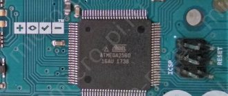
Arduino includes a microcontroller, which is a microprocessor assembled on one circuit. Its specialty is its ability to perform simple tasks. Depending on the model, the Arduino device can be equipped with various types of microcontrollers.
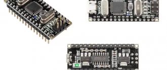
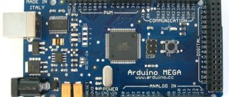
There are several models of boards, the most common of them are UNO, Mega 2560 R3.
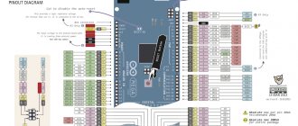
An equally important feature of the printed circuit board is the presence of 22 pins, which are located around the perimeter of the product. They are analog and digital.
The peculiarity of the latter is that it is controlled using only two parameters - a logical one or zero. As for the analog pin, there are many small regions between 1 and 0.
Today, Arduino is used to create electronic systems that can receive information from various sensors (digital and analog).
Arduino devices can work in conjunction with software on a computer or independently.
As for the boards, you can assemble them yourself or purchase a finished product. Arduino programming is done in the Wiring language.
READ ON THE TOPIC: Xiaomi Smart Home, review, equipment, connection and setup with your own hands, scenarios.
How does such a smart home work?
To create a smart home with your own hands, you will need the Little Brownie Kuzya skill. Through it you can not only control your smart home, but also integrate virtual devices directly into Yandex.Alice. This means you won't have to constantly open a skill just to turn off a light bulb. The skill will communicate with the microcontroller via webhooks.
The Blynk platform is a great platform for webhooks - a control panel for devices on Arduino and Raspberry Pi. There you can easily create a graphical interface through which you can control the device via Wi-Fi (and also via Ethernet, USB, GSM and Bluetooth).
What does Arduino control?
Thanks to the large number of pins on the printed circuit board, it is possible to connect many different devices to Arduino, namely:
In addition, a set of sensors is connected to Arduino depending on the tasks assigned to the system. As a rule, sensors for light, smoke and air composition, magnetic field, humidity, temperature and others are installed.
Thanks to this feature, Arduino becomes a universal device - “a brain device with the ability to be configured taking into account the tasks at hand.
Table for connecting circuit elements to Arduino UNO R3
Let's summarize all the connections between Arduino and external devices into a single table, which will help in assembling the finished circuit.
| Where | Arduino UNO R3 pin | Device pin/contact |
| Module for 4 relays D0 general lighting, D1 heating, D2 light in the pantry, D3 outdoors. | D0 | D0 |
| D1 | D1 | |
| D2 | D2 | |
| D3 | D3 | |
| Arming/disarming button | D4 | |
| Economy mode/people at home key | D5 | |
| D6 | ||
| Communication with the modem | D7 | RX |
| D8 | TX | |
| LED security disabled (red) | D9 | |
| Security activated (green) | D10 | |
| Owners of the house (kr) | D11 | |
| Economy mode (green) | D12 | |
| Turning on the modem | D13 | D9 |
| Reed switch storage room | A1 | |
| Reed switch door/gate | A2 | |
| Thermometer | A3 | |
| Determining the presence of a 220 V network | A4 |
The planned system did not completely occupy all the pins of the microcontroller. There is still room to add an analog sensor and one control line. An option is to use free contacts for the smoke sensor and alarm. If you plan to expand the design further, you will have to take the Arduino Mega microcontroller. It has more I/O ports and memory, with full software compatibility.
How the system works
The Arduino device works as follows. Information collected from various sensors in the home is sent wirelessly to a tablet or PC. Next, using special software, the data is processed and a specific command is executed.
The main function is performed by a central sensor, which you can purchase or assemble yourself. The connectors on the boards are standard, which greatly simplifies the selection of components.
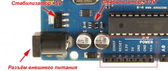
Nutrition
The Arduino is powered via a USB connector or from an external power supply. The voltage source is determined automatically.
If you select the option with external power supply not via USB, you can connect a battery or power supply (voltage converter). In the latter case, the connection is made using a 2.1 mm connector with a “+” on the main contact.
The wires from the battery are connected to various terminals of the power connector - Vin and Gnd.
For normal operation, the platform requires a voltage of 6 to 20 Volts. If the parameter drops below 7 volts, the 5V pin may have less voltage and risk a failure.
If you supply 12 V, the voltage regulator may overheat and damage the board. For this reason, the optimal level is power supply using 7 - 12 V.
Unlike previous types of boards, the Arduino Mega 2560 works without the use of a USB FTDI microcontroller. To ensure information exchange via USB, a USB-to-serial converter programmed for the converter is used.
POPULAR WITH READERS: What is a CLAP smart home.
The Arduino has the following power pins:
- 5V - used to supply voltage to the microcontroller, as well as other elements of the printed circuit board. The power supply is adjustable. Voltage is supplied via a USB connector or from the VIN pin, as well as from another 5 Volt power source with the ability to regulate.
- VIN - used to supply voltage from an external source. The output is necessary when it is not possible to supply voltage via a USB connector or other external source. When voltage is applied to the 2.1mm jack, this input is used.
- 3V3 is a pin whose voltage is a consequence of the operation of the FTDI chip itself. The maximum current consumption level for this element is 50 mA.
- GND - grounding terminals.
The circuit diagram of the board in pdf format can be viewed HERE.
Connection
Arduino capabilities allow you to connect a group of devices that provide stable communication with a PC, as well as other system elements - microcontrollers or the same Arduino boards.
The ATmega 2560 model is distinguished by the presence of 4 ports through which data can be transferred for TTL and UART. A special ATmega 8U2 chip on the board transmits the interface (one of them) via a USB connector. In turn, programs on the PC receive virtual COM.
There are nuances here that depend on the type of operating system:
- If Linux is installed on the PC, recognition occurs automatically.
- If you are using Windows, you will need an additional .inf file.
Using the monitoring utility, you can send and receive information in text format after connecting to the system.
Flashing TX and RX LEDs indicate data transmission. A special Software Serial library is used to send information sequentially.
Features of the ATmega 2560 include the presence of SPI and I2C interfaces. In addition, Arduino includes the Wire library.
Advantages of the 2560 microcontroller
Arduino is a popular platform for implementing various projects, suitable for engineers who do not want to program “empty” microcontrollers and, in principle, want to reduce communication with the software environment to a minimum.
But even in the basic configuration it has its pitfalls, which it is better to know about in advance.
Gradually setting yourself more complex tasks and engaging in new developments on this MK, you will eventually encounter two main problems with standard boards:
- Suboptimal sizes, not suitable for convenient placement in many cases.
- Lack of number of pins for data input/output.
Problem #1
It is extremely easy to minimize the space you take up - just use special types of MK, be it nano or mini. There are some features here with a lack of memory, for example, on the Attiny85, but for simple functionality this is not so significant.
Of course, for more complex tasks you can buy special modules with additional memory for instructions, but this completely eliminates all the advantages of the nano, because the reduced size will be compensated by an additional slot for the chip and a occupied pin. This problem does not apply to all boards, and the same nano is capable of completely copying the functionality of the uno.
Problem #2
Less pleasant, but there are several ways to solve it:
As we see, both ways out of the situation involve “crutches”, and they cannot be called elegant. But this is far from the only problem. They either work partially or neutralize the advantages of the system, which is absolutely unacceptable for any complex projects.
Fortunately, there is a third approach that is being used more and more often - Arduino Mega 2560, projects on which no longer suffer from the abundance of these “crutches”. There is also an analogue of this board that supports USB hosts, but let's first look at the main MK.
The first thing that catches your eye when you meet the 2560 is its appearance, because it is 1.8 times longer than the UNO, which is a necessary evil in order to accommodate as many as 54 ports on it.
Moreover, 15 of them can be used as sources of PWM signals to regulate current power or other system parameters. Regulation is carried out using pulse-width modulation, and additional 16 input ports can process digital signals and be used as the same digital outputs. As a result, we get a thinner, longer and more functional board.
For communication with several types of devices, 4 UART interfaces are installed, on pins 0, 1, 14, 19. Moreover, one of them is directed to USB using the ATmega8U2 microcontroller, used as a replacement for the usual USB-TTL, which was used everywhere in older boards.
But, what’s more important, the firmware is located in a public repository and, accordingly, is available for downloading and modification to anyone. For communication with displays, there are SPI and I2C technologies, which you can also use in your project.
Project development
There are many Arduino devices on the market today, with different configurations. But there is no universal solution “for all occasions”. Depending on the task at hand, each kit is selected individually. To avoid mistakes, project development is required.
What projects can be created on Arduino?
Arduino allows you to create many unique projects. Here are just a few of them:
- Solving a Rubik's cube (the system solves it in 0.887 s);
- Controlling humidity in the basement;
- Creation of unique paintings;
- Sending messages;
- Balancing robot on two wheels;
- Sound spectrum analyzer;
- Origami lamp with capacitive sensor;
- Robotic arm controlled by Arduino;
- Writing letters in the air;
- Flash control and much more.
We select the equipment for the project using the example of Arduino Mega 2560 R3
To create a full-fledged Smart Home system and perform its assigned functions, it is important to correctly approach the configuration and selection of equipment.
What's included in the package?
If your goal is a “Smart Home” based on Arduino, you need to prepare the following equipment - the Mega 2560 R3 board itself, an Ethernet module (ENC28J60), a motion sensor, as well as other sensors and controllers.
In addition, it is worth preparing a twisted pair cable, a resistor, a relay, a switch and a cable for the Ethernet module.
Additional tools are also needed - screwdrivers, soldering irons, etc.
Please note that you should buy kits for installing the system at certified points. This is due to the fact that the project uses electricity, and the use of counterfeits can lead to a decrease in safety.
All programs for adaptation can be found online on the official Arduino website https://arduino.ru. When choosing sensors, you should focus on the tasks that the Smart Home must solve.
Typically, motion, temperature, door opening and light sensors are required. The role of a door opening sensor can be performed by a regular reed switch.
The board is flashed using special software designed for various operating systems, including a USB cable. In this case, there is no need for programmers.
As for the software used in Arduino, it is written in C language. There are certain restrictions on the number of bytes, but the current memory is sufficient to implement the task.
Add-on boards (shields)
To increase the capabilities of motherboards, Shields are used - additional devices that expand the functionality. They are manufactured for a specific form factor, which distinguishes them from modules that are connected to ports. Shields are more expensive than modules, but working with them is easier. They are also equipped with ready-made libraries with code, which speeds up the development of your own control programs for a smart home.
Proto and Sensor shields
These two standard shields do not add any special functionality. They are used for more compact and convenient connection of a large number of modules.
Proto Shield is an almost complete copy of the original in terms of ports, and you can glue a development board in the middle of the module. This makes it easier to assemble the structure. Such add-ons exist for all full-length Arduino boards.
Proto Shield is placed on top of the motherboard. This slightly increases the height of the structure, but saves a lot of space in the plane
But if there are a lot of devices (more than 10), then it is better to use more expensive Sensor Shield switching boards.
They do not have a bradboard, but all port pins are individually supplied with power and ground. This allows you to avoid getting tangled in wires and jumpers.
The surface area of the motherboard and sensor boards is the same, but there are no chips, capacitors and other elements on the shield. This frees up a lot of space for full connections.
This board also has connectors for easily connecting several modules: Bluetoots, SD cards, RS232 (COM-port), radio and ultrasound.
Connecting auxiliary functionality
Shields with functionality integrated into them are designed to solve complex but typical problems. If you need to implement original ideas, it is better to choose a suitable module.
Motor Shield. It is designed to control the speed and rotation of low-power motors. The original model is equipped with one L298 chip and can drive two DC motors or one servo at the same time. There is also a compatible third-party part that has two L293D chips with the ability to control twice as many drives.
Relay Shield. A frequently used module in smart home systems. A board with four electromechanical relays, each of which allows the passage of current with a force of up to 5A. This is enough to automatically turn on and off kilowatt devices or lighting lines designed for 220 V alternating current.
LCD Shield. Allows you to display information on a built-in screen, which can be upgraded to a TFT device. This extension is often used to create weather stations with temperature readings in various living spaces, outbuildings, garages, as well as temperature, humidity and wind speed outside.
The LCD Shield has built-in buttons that allow you to program information scrolling and select actions to send commands to the microprocessor
Data Logging Shield. The main task of the module is to record data from sensors onto a full-format SD card up to 32 Gb with support for the FAT32 file system. To record to a micro SD card you need to purchase an adapter. This shield can be used as an information storage, for example, when recording data from a DVR. Manufactured by the American company Adafruit Industries.
SD Card Shield. A simpler and cheaper version of the previous module. Many manufacturers produce such extensions.
Ethernet Shield. Official module for connecting Arduino to the Internet without a computer. There is a slot for a micro SD card, which allows you to record and send data via the World Wide Web.
Wi-Fi Shield. Allows wireless exchange of information with support for encryption mode. Serves to connect to the Internet and devices that can be controlled via Wi-Fi.
GPRS Shield. This module is usually used to communicate between a smart home and its owner via mobile phone via SMS messages.
Beginning of work
Once the necessary equipment is prepared and the project is developed, you can begin to complete the task.
Stages
When organizing a Smart Home system based on Arduino, you should follow the following algorithm:
- Installation of program code;
- Application configuration for the device used;
- Port forwarding (for router);
- Carrying out tests;
- Making edits and so on.
The Internet has all the necessary software for the equipment used - just download it from the official website and install it (see link above).
The application allows you to see information about sensors. If required, the IP address settings can be changed.
Sequence of actions when connecting to a computer
To get started with Arduino on Windows, follow these steps:
- Prepare the necessary equipment - USB cable and Arduino.
- Download the program from arduino.cc/en/Main/Software.
- Connect the board using a USB cable. Make sure the PWR LED lights up.
- Install the necessary set of drivers to work with Arduino. At this stage, you should start the driver installation and wait for the process to complete.
Then click on the “Start” button and go to the control panel. There, open the “System and Security” tab and select the “System” section. After opening the window, select “Device Manager”, click on the Arduino name and use the right mouse button to specify the driver update command. Find the line “Browse my computer for Driver software!”, click on it and select the appropriate driver for your board type - ArduinoUNO.inf (located in the drivers folder). It could be UNO, Mega 2560 or another. - Launch the Arduino development environment by double-clicking on the application icon.
- Open the finished example (File - Examples - 1.Basics - Blink).
- Select a board. To do this, go to the Tools section, and then to the Board Menu.
- Install the serial port (you can find it by unplugging and plugging the cable).
- Download the sketch in Arduino. Click on “Upload” and wait for the TX and RX LEDs on the board to blink. Finally, the system shows that the download was successful. A few seconds after completion of work, LED 13 L should light up (it will flash orange). If so, the system is ready to perform tasks.
Working with a router
For the Smart Home to function properly, it is important to handle the router correctly. Here you need to perform the following steps - open the configuration, specify the Arduino IP address, for example, 192.168.10.101 and open port 80.
Afterwards you need to assign a domain name to the address and proceed to the project testing process. Please note that for such a system it is prohibited to use a public IP address, because in this case there is a high risk of hacking through the Network.
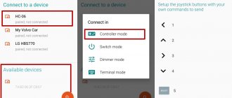
Setting up the skill “Kuzya the Little Brownie”
Go to the skill website and log in via Yandex. Next, click on Add HTTP Rule (GET)
. A form for setting up a rule will open in front of you.
Activation phrase
— the name of the request that will be displayed in the list (for example, “kitchen light, turn on”).
If you do not plan to control your smart home specifically from within the skill, then the phrase will not be needed anywhere else.
Leave
field Kuzi In the URL
, insert the corresponding webhook to turn on the light (virtual port). The remaining parameters can be left unchanged. After this, you need to make an identical rule for turning off the lights.
An example of setting up a rule to turn on the light.
Next, you need to go to the virtual devices tab and add the “Lamp” device. Here you need to give the device a name by which Alice will identify it. For example: light, sconce, backlight, lamp or floor lamp. Location
— the room in which the device will be installed. This is necessary in case there are elements of the same name in several rooms. In addition, with one voice command you can turn on and off all devices in a specific room.
B On/Off rule
Select the appropriate queries from the list. The lamp has the ability to control brightness. To do this, you need to create another rule, but set the value of the value parameter to {value}. Then a number from 0 to 100 will be substituted into the request, which will indicate the required brightness. All you have to do is process this value in the sketch.
Example of setting up a virtual device
Note If you plan to change the brightness, then the value
in the enable webhook you need to change from 1 to 100.
Modern gadgets that you can make yourself
tproger.ru
Expanding capabilities on Arduino
One of the capabilities of a smart home is visualization of the state of automation and processes occurring in the system. To do this, it is recommended to use a separate server that provides state processing (the Node.js program can be used).
The mentioned software technology is used to solve Internet problems, therefore, to visualize the “Smart Home”, the Java Script language is used (it is with its help that the processor and server are created). The results can be seen on your computer or PC screen.
To implement your plan, a laptop, a regular PC or a Raspberry Pi will be suitable. The use of such a system allows you to increase its capabilities. So, if the Arduino board has a small amount of memory, there are no such restrictions on the server. The program is written in such a way as to provide full control of the platform.
If desired, you can set an algorithm that will record the fact that a person is in the house and collect this information. If the owner returns around 5:30 pm every day, the boiler or heating devices can be turned on an hour before. Upon arriving home, a person finds himself in a warm building with hot water.
The program can remember the time when the owner goes to rest and turn off the water heating. There are many such nuances that, if necessary, are introduced into the program. It is the presence of an external PC that gives great opportunities to the Arduino controller.
Communication with Arduino
To know what actions to perform, the processor must receive the appropriate command. Communication is carried out using a special language, which is adapted for working with Arduino and is quite simple. If desired, it is easy to work with even without programming skills.
Formatting and sending a message to the controller is called programming. To simplify the process, the Arduino IDE has been developed, which includes many programs. Studying them allows you to get a lot of useful information about working with Arduino.
Creating systems on the Arduino platform
Arduino is a platform for developing electronic devices with automatic, semi-automatic or manual control. It is made according to the principle of a designer with clearly defined rules of interaction between elements. The system is open, which allows third-party manufacturers to participate in its development.
A classic “smart home” consists of automated units that perform the following functions:
- collect the necessary information through sensors;
- analyze data and make decisions using a programmable microprocessor;
- implement the decisions made by issuing commands to various devices.
The Arduino platform is good precisely because it is not locked into a specific manufacturer, but allows the consumer to choose the components that suit him. Their selection is huge, so you can realize almost any idea.
We recommend checking out the best smart devices for your home.
To learn how to work with Arduino, you can purchase a Starter Kit on the manufacturer’s website. Knowledge of technical English is required, since the documentation is not Russified
In addition to the variety of connected devices, the programming environment implemented in C++ adds variety. The user can not only use the created libraries, but also program the reaction of system components to emerging events.
How can you manage?
As noted, the Node.js server allows you to connect equipment in your home. One of the ways to manage processes is cloud services on the Internet. In this case, you can turn on the heating or boiler one to two hours before arrival.
Another way is to control using messages (MMS or SMS). This option is relevant when there is no connection to the Internet. One of the advantages of the system is the ability to obtain information about a force majeure situation (for example, a leak). The Edison board from Intel helps here.
Control and management of the climate system
The owner can heat the room, as well as clean, humidify and ventilate the air. Let’s say that by the time you arrive, warm up the room to a certain temperature.
The main advantages of this function:
- Heating or cooling the room temperature is carried out by one common system.
- Possibility of adjusting any temperature conditions in the room, in accordance with the weather conditions of the climate.
- Each individual device has its own special sensors that regulate the operation of a particular mechanism and allows you to control the internal climate in the room.