When arranging a home electrical network or doing electrical repairs yourself, you need to figure out how to connect the lamp through a switch, the order of which depends on a variety of factors. In this case, not only the type of switch must be taken into account, but also the class of the lighting device connected to the household system. To understand the features of these electrical procedures, you should understand how to properly connect the device in each specific case. The following options are possible:
- Using a single-key device.
- Option for connecting to a two-key switch.
- The same thing, but only concerning a different type of device (with three keys, for example).
- Power supply to the lamp from any outlet available in the room, implemented by laying a separate line from it.
But it is also important to familiarize yourself with the methods of connecting several light bulbs to one switch, as well as the options when LED or spotlights are connected to them.
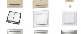
Types of light switches
Household switching devices can be classified according to different criteria. First of all, they are divided by purpose. It is determined by the type of contact groups and their number. The most common devices are key ones. They have a contact group for closing and opening an electrical circuit. Based on the number of contact groups, such devices are divided into:
- single-key – with one contact group;
- two-key – with two independent groups;
- three-key - with three.
Designation of switches on diagrams and drawings.
There are also pass-through and crossover devices for creating light control schemes from several points.
Contact diagrams for various household appliances.
According to the method of influence they can be divided:
- keyboards;
- push-button – with a non-latching button to control the light via pulse relays;
- rotary - to turn on the lighting, the control element must be turned;
- touch, remote controlled, etc. – to create systems such as “Smart Home”.
By type of installation, switches are divided into:
- external – used for open or hidden wiring;
- built-in – used for hidden wiring.
According to the degree of protection, switches are divided into devices for indoor installation and outdoor installation (IP no less than 44). Also, when choosing, you need to pay attention to the rated current - it should cover the current of the intended load with a margin.
Types of lamps for home use
Tube progress keeps pace with switches. Their diversity is also impressive.
But here, too, some more popular types are defined:
- Incandescent light bulbs are established home light sources in a round glass bulb with a vacuum and a tungsten filament inside.
- Halogen lamps are the same incandescent lamps filled with a special gas. It increases service life and minimizes the size of their flasks. Disadvantage: When installing, you cannot touch the glass of the flask with your hands.
- Fluorescent fluorescent lamps are not very common at home, but they are also traditional lighting devices (hereinafter simply “fluorescent lamps”).
- Energy-saving LED lamps, as the name suggests, use the glow of groups of LEDs. They can be fixed into ordinary screw-in sockets (hereinafter simply “LED lamps”).
Energy-saving fluorescent light bulbs are increasingly replacing the usual ones. The operating principle is similar to fluorescent lamps. They are screwed in like incandescent lamps (hereinafter simply “energy-saving lamps”).
Preparing for work, choosing equipment
To successfully connect a light bulb, certain materials and tools are required. Without this, there is no need to talk about any quality that determines the durability of the system.
A set of necessary tools
To perform installation you will need:
- installer's knife for stripping insulation;
- if you have an insulation stripper, it will be useful for stripping individual conductors;
- To shorten cables and wires to the required length, you will need wire cutters;
- to install electrical appliances you will need a set of screwdrivers;
- if you plan to solder twists or tin the stripped sections of wires, you will need an electric soldering iron with a set of consumables (flux, solder).
During the work, you will also need other small plumbing tools (pliers, hammer, etc.).
Conductor Products
When choosing a cable for a lighting system, you should take it as a basic rule - no aluminum. The relative cheapness of aluminum conductor products is balanced by potential problems in further operation:
- the plasticity of this metal leads to deterioration of contacts in the clamping terminals; they will need to be periodically tightened;
- its fragility will lead to problems during subsequent repairs;
- the tendency to oxidize in air will also not improve the contact (copper is also not free from this drawback, but here the problem can be radically solved by tinning the stripped areas).
In addition, the resistivity of aluminum is 1.7 times higher than that of copper. Therefore, you will have to choose conductors with a larger cross-section. This also somewhat offsets the financial savings.
Tool for getting the job done
In the process of performing electrical work, a home handyman will need a set of the following installation tools:
- Sharp knife.
- Pliers (pliers).
- Side cutters.
- Slotted screwdrivers, thin and medium, possibly Phillips medium.
Electrical tape may be required to insulate the wire connections inside the junction box or light housing. In these cases, it is recommended to use CB tape. Over time, it does not melt or stick to the constantly heating contacts it insulates, but only dries out. If necessary, crumble well with pliers.
It’s great if you have a special wire stripping tool - a stripper or wire cutters with slots for stripping insulation. In the absence of such devices and a large amount of work, you can get by with a folk remedy by modifying the side cutters.
To do this, use a file to make opposite cuts in the cutting edges closer to the hinge, which together should form a hole slightly larger than the diameter of the exposed wire strand.
Conductor markings
To perform electrical installation work, it is more convenient to use cables, all conductors of which are marked. It is performed using insulation of various colors. For three-core cables used in single-phase 220 volt networks, the color marking indicated in the table has become a kind of standard.
| Purpose of the conductor | Designation on diagrams | Color |
| Phase | L | Red, brown, white |
| Null | N | Blue |
| Protective | P.E. | Yellow-green |
Failure to comply with color matching will not lead to a disaster or loss of network functionality, but to confusion and installation errors - almost 100%.
A less common option is digital marking. Numbers from one to the maximum number of cores in the cable are applied to the insulation along the entire length of the conductor. If an unmarked cable is used, after laying and cutting it, you must call it using a multimeter or other method and mark the wires yourself.
Connection of copper and aluminum conductors
It is a well-known fact that conductors should not be in direct contact in electrical wiring. Copper and aluminum have a significant difference in electrochemical potential, so an EMF will occur at the point of their contact. It is insignificant, but over a long period of operation, the current constantly flowing through the joint will cause electrochemical corrosion when interacting with atmospheric moisture. It leads to the formation of an oxide film, poor contact and local overheating, and these effects will only increase over time. The result will be a burnout of the contact point, or even a fire of the insulation of conductors or other nearby objects.
Therefore, copper and aluminum wires can only be connected through terminals made of steel . Better yet, forget about the very possibility of making aluminum wiring and make it only from copper conductors.
Selecting a junction box
If installation is carried out in a residential area, choosing a junction box comes down to purchasing a plastic box suitable for:
- external wiring;
- hidden wiring;
- installation on a plasterboard partition.
You also need to pay attention to the size - if you plan to make a large number of connections in one box, then the dimensions of the box should be increased.
But if the junction box is installed indoors with special conditions (manufacturing, etc.) or outdoors, then you need to pay attention to the degree of protection against moisture and dust IP, and select a product that meets the operating conditions.
Wiring and making connections
The key point when connecting a lamp through any switch is the quality of the electrical connections. If this job is done poorly, everything else is meaningless.
Removing insulation
First of all, the cables must be shortened to the required length. This can be done using wire cutters. Next, remove the insulation in the desired areas.
The cable contains at least two layers of insulation:
- external – common to all conductors;
- internal - individual for each core.
Both layers can be removed with a mechanic's knife - cut the plastic along the ring, being careful not to touch the wires, and remove the resulting piece.
Removing external insulation with a knife.
It is even better to use special pullers for external and internal insulation.
Removing external insulation with a stripper.
Removing the insulation of the cores with a stripper.
Their advantage is that you can adjust the depth of the cut so as not to damage the wires. In addition, the wire looks neater after cutting.
Performing twisting
When disconnecting the wires in the junction box, you can use clamp terminals. But there is a reasonable opinion that this good, convenient and progressive method does not guarantee reliable contact for many years (especially at high currents), so the good old twisting will not leave the scene for a long time.
Before starting work, it is worth remembering once again that you cannot twist copper and aluminum conductors. It is possible to twist aluminum ones together, but the fragility of this metal imposes restrictions on this method. Therefore, it is optimal to twist copper conductors together. In addition, copper is easily soldered, so after twisting it is recommended to solder the contact point. This will protect the surface of the conductor from oxidation and give the connection mechanical strength.
Twisting after soldering.
Another option is to weld the ends of the twisted wires. To do this, you will need an industrial or homemade welding machine.
Twisting after welding.
Twisted wires can be crimped, but this will require copper sleeves, special tools and skills.
A set of materials and tools for crimping.
In any case, the twists must be insulated. In addition to electrical tape, special plastic caps are suitable. When using heat shrink, remember that the sharp ends of the wires can damage the applied thin tube. Therefore, it is advisable to use heat shrink in two layers.
Insulation of twists with heat shrink tube.
A good alternative to spring terminals and twisting is the use of screw terminal blocks. At the same time, the problem of contact between aluminum and copper is solved. But they take up more space in the distribution box and installation is more labor-intensive.
An example of connecting wires using Wago self-clamping terminal blocks.
Wall chipping
If you choose the option of hidden wiring, before starting installation you need to make channels in the wall for laying cable products - grooves (the term grooves is found in technical and regulatory literature). It is best to do them using a special power tool - a wall chaser. If you don’t have one, a grinder or hammer drill will do. As a last resort - a hammer and chisel.
The work is very dusty, so it is necessary to take measures to protect the respiratory system, as well as surrounding objects.
Several restrictions must be observed when working:
- grooves can be laid strictly horizontally or vertically (at an angle of 0 or 90 degrees);
- You cannot cut horizontal channels on load-bearing walls.
The remaining rules can be studied in SP 76.13330.2016 (current edition of SNiP 3.05.06-85).
Then, in pre-selected places, it is necessary to arrange recesses for installing distribution boxes and socket boxes. This is done using a core drill.
Switch installation
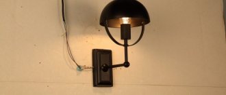
With open wiring, the switch is installed on a backing panel or directly on the wall.
Installation of surface-mounted switch.
If the built-in option is selected, the socket box is first mounted and the cable is routed into it.
Installation of socket box and cable outlet.
Next, the cable is cut as indicated above: it must be shortened and stripped of insulation.
Then you should remove the decorative parts from the switch - the frame and keys.
Switch with removed decorative elements.
Next you need to connect the wires to the terminals. If the terminals are clamping, then the cores are simply inserted into them. If they are screw-type, they must be securely tightened with a screwdriver.
Connecting wires to clamp terminals.
Next, tighten the bolts of the expansion petals until the device is completely fixed in the socket box and, if provided for by the design, attach it to the wall with self-tapping screws.
Fastening the switch with self-tapping screws.
After this, you can install the plastic parts back, apply voltage and test the operation of the circuit.
More detailed instructions for installing the switch are described in a separate article.
Connection diagram for a simple lamp
Using the example of the simplest single lamp, the “Ilyich bulb,” we will consider the main elements of the electrical circuit.
In any apartment, wiring is usually laid in the wall along the perimeter at a distance of about 10-15 cm from the ceiling. This is a highway. Branch boxes are installed on it. They are needed in order to “crash” into the main cable and power a socket or switch with a lamp.
Let's look at the wiring diagram in the junction box. The cable goes down from it to the switch, up to the lamp, and to the left and right - the main cable. In fact, this is, of course, a convention; the order in which the wires are inserted into the box is determined only on the basis of considerations of expediency.
Neutral wire, easy to use. It branches directly from the main line and goes straight to the lamp. The situation with the phase wire is not much more complicated; it also goes to the lighting fixture, but only through the switch. That's all the wisdom.
A regular single-key switch has two contacts on the back for connecting wires. In this case, polarity does not matter. How to connect a chandelier to two switches? Will the task become much more difficult?
Connection using a junction box
Connection using a junction box is always recommended, with the exception of implementing a lighting control circuit from several points using sequential connection of pass-through and cross switches. In this case, it is better to lay cables and connect with a cable.
If installation with a junction box is chosen, it is carried out according to the following principles:
- a two-core power cable (three-core if there is a grounding conductor) with phase and neutral wires is laid from the switchboard to the box;
- each luminaire has its own two-core cable (three-core in TN-S or TN-CS ) with cores L and N ( PE );
- conductors N and PE follow in transit through the box to the lamps; if necessary, they are branched according to the number of lamps;
- the phase conductor has a break, a switching device is connected to it according to the diagram;
- A cable with the appropriate number of cores is lowered to the switch.
PE conductor must be laid, even if lamps without grounding are used (for example, with incandescent lamps). This will help avoid problems in the future when reconstructing the network.
We recommend that you see clearly how the masters do it.
Tools and materials
The practical implementation of the task of how to properly connect a switch will require certain tools and materials. For example, spring clamps or terminal blocks may be used to connect wires inside a junction box.
The complete list includes the following items:
- Switches. Usually one- or two-key, or having three keys are used, connected according to their own circuits to one or two light bulbs.
- Cables and wires. They are selected in accordance with the project, based on the technical characteristics of the future network coming from the box.
- Distribution boxes. It is best to use plastic products that are fire-resistant and have high dielectric properties. Instead, you can connect from a wall outlet.
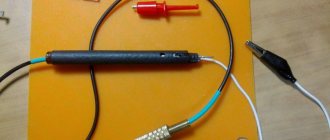
- Indicator screwdriver. Determines the presence or absence of voltage before and after installation. You can use a tester if it is available.
- Wire cutters, pliers, pliers. Used to connect wires to each other.
- Insulating materials, fasteners and parts.
- Impact drill or hammer drill. Necessary when installing hidden wiring.
Connecting a switch with lamps connected in parallel
This connection has no fundamental differences from the usual one - the phase and neutral wires are drawn to the first lamp in the diagram, from there in a loop to the second, and so on. If one lamp burns out, the others will remain in operation. One has only to remember that in such a circuit the switch must be designed for the total current of all lamps .
Diagram of parallel connection of lamps.
Switching the socket and switch in the electrical distribution box
People often ask how to connect lamps to a switch and an outlet, which is also in the room. The main thing is that they are not powered in series. It is wrong that when you turn off the light, you will de-energize appliances that operate from this outlet.
To do this, after entering into the distribution box, one core is directed to it, and the other, independent, is pulled to the switch. The “0th” cord is also different for each consumer. This results in two independent branches.
A special case where it is necessary that the power supplied to the outlet be interrupted at will. Then a serial connection of the lamp with a switch and a connector is used. This means that the output of the switch is the input for the socket. And only after that the wire is pulled to the junction box. As a result, after switching on, the lamp lights up and current flows to the socket, and after switching off, all connected consumers are de-energized along with the light source. In everyday life, such a scheme is rarely used.
Schematic connection examples
As a simple example, let’s look at what the circuit diagram for connecting a switch to one light bulb looks like (protective grounding available). A three-core cable runs from the switchboard into the box, and a three-wire cable also goes to the lamp. The phase conductor is broken; a switching device is connected to the gap using a two-core cable.
Diagram of wiring and connection of conductors for the option with a single switch.
A similar circuit with a triple switch and three lamps looks much more complicated. A larger number of connections are made in the box, so you need to choose a larger distribution box.
Scheme of laying and connecting conductors for the version with a triple device.
Installing a circuit with two lamps and two double pass-through switches in a box looks even more difficult. It is better to implement such a scheme using a cable.
Scheme of laying and connecting conductors for the option with two pass-through devices.
Obviously, the second option simplifies installation and reduces the consumption of cable products.
Layout of the cable and connection of conductors for the option with two pass-through devices.
Connection diagram for two switches
Installing such a circuit on one light bulb is not difficult. At the stage of creating the wiring at the points where the installation of changeover structures is planned, it is necessary to lay a three-core cable in advance before the first two. If you need more light switches, then you will have to use a four-core cable, which must be stretched to the next ones.
To be able to control the lighting from two places simultaneously, you need to purchase pass-through switches, which are equipped with two switching positions and three contacts. In this case, the switching must be of a reversible nature, with the first node being common to the other two.
Components and devices
When considering the “two switches for one light bulb” circuit, which has two changeover switching structures, we can distinguish the components:
- connection (branch) box, which is used to protect electrical connecting cables - present in every room; in large rooms several of them are installed;
- connecting wires (two-, three- and four-wire);
- the lamp itself;
- two pass-through switching devices.
Principle of operation
Installation of a pass-through lamp switch:
- The “zero” wire is laid from the source to the branch box, then goes to the lamp.
- The “phase” wire is drawn from exactly the same source to the same box, and then laid to the common contact of the first switch.
- Using a junction box, the two changeover contacts of the first switch are connected to exactly the same parts of the second switch.
- The phase from the common contact of the second switch is connected to another electrical unit of the lamp.
The installation work of a control system for one lighting fixture operating from two places simultaneously is not complicated.
Installation is carried out as follows:
- Install reversible switching structures in the required places.
- Do not remove three-core cables from them.
- Install one or, if necessary, several electric lamps connected in parallel to each other.
- Remove a two-core cable from one or several lighting fixtures.
- Install the junction box, the location of which corresponds to convenient access to it and the shortest distance of the cable length.
- Connect the wires from the changeover structures, power supply and the lighting fixtures to the box.
- Connect them as described in the above paragraphs.
Errors and possible malfunctions
One of the main mistakes when connecting a switch is incorrect determination of the location of its terminals. Many people believe that by default a separately made terminal is always common. This is not true - manufacturers can arrange the terminals in any order . Therefore, before starting installation, it is necessary to determine the terminals of the device. This is easy to do if a diagram is applied to the device. If not, you can use a multimeter to test the internal connections. At the same time, this process will test the device for serviceability.
Another common mistake is incorrect connection of the conductors in the box. To reduce it to a minimum, it is necessary to use cables with marked cores. If the cores are single-colored, after laying and cutting the cables, you need to call them with a multimeter and mark them yourself.
Video lesson: 5 mistakes when disconnecting junction boxes.
How to avoid mistakes
Electrical appliances must be connected to the network in compliance with electrical regulations. The connection features are not obvious and may be incomprehensible to people far from the topic.
It is important to consider:
- Each type of connection has features associated with Ohm's law. In a series connection, the current is equal in all parts of the circuit, while the voltage depends on the resistance. In a parallel connection, the voltage is the same, and the total current is the sum of the values of the individual sections.
- Any circuit should not be overloaded, as this can lead to unstable operation of the devices and damage to the conductors.
- In a parallel connection, the cross-section of the wires must correspond to the applied load, otherwise overheating of the conductors is inevitable, followed by melting of the winding and a short circuit.
- A phase is supplied to the switch, zero goes to the lighting fixture. Failure to comply with this rule may result in electric shock when replacing the lamp, since even when the device is turned off, the device is energized.
- The main wire from the lamp is connected to the common contact. If you connect it to a tap, only part of the circuit will work.
- Before installing the switch, it is better to mark the wires in advance. During installation, it will be easy to connect the same conductors together.
Failure to follow the recommendations may result in unstable operation of lighting equipment, rapid lamp burnout, and serious injury that could lead to life-threatening injuries.
Security measures
The main safety measure when installing wiring is to perform all actions with the voltage removed . If the lighting system is being made from scratch, then connecting the power wire to the circuit breaker is done last. If work is being carried out to reconstruct or repair an existing circuit, it is necessary to carry out technical measures:
- turn off the circuit breaker (or circuit breaker) of the lighting system;
- take measures to prevent spontaneous or erroneous switching on - disconnect the supply wire from the terminal of the machine;
- if the power supply system is made according to the TN-S principle, then the disconnected wire must be connected to the ground bus;
- check that there is no voltage on the phase wire.
Important! It is necessary to check the absence of voltage directly at the place of work - in the distribution box or at the switch terminals.
Labor safety rules when working in electrical installations also require the use of dielectric gloves, carpets, and insulated power tools. It is unlikely that anyone will have laboratory-tested protective equipment in their everyday life, but if possible, they should be used. There is no such thing as too much security. At the very least, you can monitor the insulation condition of hand tools visually. With this approach, the likelihood of electric shock during operation will be minimal, installation will be carried out accurately, quickly, and will last a long time and reliably.
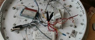
LED T8 lamps instead of fluorescent tubes
Another common and affordable way to quickly and inexpensively connect an LED lamp at home is to replace it with a fluorescent tube lamp in fluorescent lamps. For this purpose, T8 ice tubes with a G13 base system are used. Their dimensions, shape and connection devices are similar to their luminescent counterparts.
Rework involves dismantling fluorescent tubes, replacing, removing some components or upgrading the circuit, as well as selecting and installing ice tubes. There are two options for upgrading lighting devices in this case:
- Based on ballast starting and control automation (old models). Be sure to remove the starter (to prevent a short circuit when turning on after installing the ice tube), select and install the LED tube according to size.