The probe is assembled on a piece of foil fiberglass and placed in a metal tube that acts as a screen. In order not to cause emergency situations when and if the probe falls on the switched-on device under test, the tube is covered with heat shrink. Without coating, the workpiece looks like this:
Disassembled probe:
Designs may vary. Just need to consider some things:
- If you perform a probe without a divider, i.e. it does not contain large resistances and switches, i.e. elements subject to electromagnetic interference, it is advisable to stretch the shielded probe wire all the way to the needle. In this case, you will not need additional shielding of the elements and the probe can be made from any dielectric. For example, use one of the tester probes.
- If the probe has a divider, then when you pick it up, you will inevitably increase interference and interference. Those. shielding of the divider elements will be required.
In my case, the connection of the tube to the screen (more precisely, to the back side of the fiberglass laminate) is made by soldering a spring onto the tectolite, which creates contact between the screen and the probe board.
As a needle I used a “Dad” from a ShR type connector. But it can be made from any other suitable rod. The connector from the ShR is convenient in that its “Mother” can be soldered into a clamp, which can be put on the probe if necessary.
Wire selection
The selection of wire deserves special mention. The correct wire looks like this:
The 3.5 mm minijack is located nearby for scale
The correct wire is a more or less ordinary shielded wire, with one significant difference - it has one central core. Very thin and made of steel wire, or even wire with high resistivity. I’ll explain why a little later.
This type of wire is not very common and is quite difficult to find. In principle, if you do not work with high frequencies of the order of ten megahertz, you may not feel much of a difference using a regular shielded wire. I have come across the opinion that at frequencies below 3-5 MHz the choice of wire is not critical. I can neither confirm nor deny - there is no practice at frequencies above 1 MHz. I will also tell you later in what cases this may have an effect.
Homemade oscilloscopes don't often have multi-megahertz bandwidth, so use whatever wire you can find. Just try to choose one with thinner central cores and fewer of them. I have come across the opinion that the central core should be thicker, but this is clearly part of the series of “bad advice”. Low resistance to the oscilloscope wire is unnecessary. There currents are in nanoamperes.
And it is important to understand that the lower the intrinsic capacity of the manufactured probe, the better. This is due to the fact that when you connect the probe to the device under test, you are thereby connecting additional capacitance.
If you connect directly to the output of a logical element or to a UPS, i.e. to a sufficiently powerful signal source that has a sufficiently low intrinsic resistance, then everything will be displayed normally. But if there is significant resistance in the circuit, then the probe capacitance will greatly distort the signal shape, because will charge through this resistance. This means that you will no longer be sure of the reliability of the oscillogram. Those. The lower the probe's intrinsic capacitance, the wider the range of possible uses for your oscilloscope.
Beginner's oscilloscope DSO138 - instructions and upgrades
Any beginner involved in radio electronics sooner or later is faced with the need to find out the signal shape and frequency. This is why there are oscilloscopes, or “donkeys” in common parlance. Therefore, today I propose to consider an inexpensive Chinese version - dso138, just right for a beginner.
Link
Initially, this model was developed as a DIY soldering kit, but Chinese friends realized that in a soldered form the demand for an oscilloscope is higher. We will consider a ready-made, working board.
Despite the fact that sellers claim a maximum testable frequency of 200 kHz, you can hardly count on such a range. Well, just to estimate approximately the frequency, without a real picture of the signal shape.
If we are realistic, we should expect a relatively passable picture at a frequency of 50 kHz; higher, there will be severe distortion. This will be enough to set up various switching power supplies.
An important point is that this oscilloscope can and should even be made portable. A pocket device, even with such low characteristics, can be a very useful assistant in the repair of low-frequency components.
So, upon purchase you receive a box with a board and display, a probe in the form of two crocodiles and “short” instructions in English. You have to figure out how to use various functions using the “highly scientific poke” method and minimal information from the Internet.
Catering
Power supply requires a 9 V source; according to manufacturers, the supply voltage can be in the range of 8-12 volts. The current consumption is not indicated, looking ahead - it is just over 100 mA.
I consider it a very practical and universal solution to power the board from a portable battery (power bank) - now almost everyone has them. In addition, by adapting the oscilloscope for a 5 V battery, the board can be powered from a telephone charger.
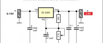
To increase the voltage from 5 to 9 volts, you can use a DC-DC converter, for example MT3608
- costs a penny in a radio store or from the same Chinese. To connect to the board, I used a computer fan connector - those with two wires, for example from an old video card, are suitable.
Either because of the input capacitor, or for other reasons, the board has large starting currents and when the entire circuit is turned on, the internal battery protection is triggered (2 A output). The problem is easily solved by adding a 0.5 Ohm resistor across the input power supply of the DC converter.
Before connecting the oscilloscope board, you need to set the voltage on the converter to 9-10 volts, this is done by rotating the trimming resistor.
Before turning it on for the first time, I recommend soldering a jumper or pin for a reference signal; the place for the jumper is located next to the power connectors. The internal generator produces rectangular pulses with a frequency of 1 kHz and an amplitude of 3.3 V. To check, you need to touch the red crocodile to the jumper; the black crocodile does not need to be hooked anywhere.
Now you can turn on the entire circuit and begin to master the simple instructions.
Instructions for use
Purpose of buttons and switches
. The board has 3 switches: input switching, sensitivity and its multiplier. The input switches to 3 positions: ❶ “GND” - the input is shorted to ground and the screen displays only its own noise, you can judge the deviation from zero of the factory settings.
Ideally, the line should be at zero, but there are deviations at different sensitivities. ❷ “AC” - The input reacts only to alternating and pulsating currents; when a constant voltage is applied to the probe, the beam only twitches a little. It will not be possible to measure DC voltage.
❸"DC" - The input is connected without an isolation capacitor, therefore it responds to both alternating voltage and direct voltage. Can be used as a millivoltmeter.
Sensitivity 1V; 0.1V; 10mV; within small limits it is regulated by X1 multipliers; X2; X5; The product of sensitivity and multiplier is one vertical cell on the screen. This value is displayed on the screen.
There are 4 buttons to the right of the screen (1 at the bottom doesn’t count - it’s a reboot): pause/start - allows you to stop the changing picture and look at it in more detail, parameter selection - allows you to select one of several parameters and use the +- buttons to adjust.
Selectable parameters (according to the chronology of clicks): ❶ The horizontal duration of one cell, in fact, is adjusted to the desired frequency; ❷ Playback mode, I didn’t notice much difference between the three modes, only minor nuances, the “AUTO” mode is the most convenient; ❸ Trigger trigger, on the edge or fall of the signal.
I don’t really understand this function, it’s related to setting up devices with a digital, logical signal; ❹ Trigger cursor, you can set the desired voltage value to trigger. When the signal curve reaches the set value, the LED under the screen is activated.
In addition, when the cursor is within the current signal, the graph is more convenient to view; it does not float. For analog measurements it is better to set it to zero; ❺ Scroll the picture left/right.
The function is useful when pausing - you can view a signal curve of a longer duration than the screen allows; ❻ Zero cursor; in fact, it can be moved both up and down. In this way, positive or negative half-waves can be examined in more detail;
As for the parameters of the measured signal in the working area of the screen, let’s figure out what they mean: Freq
— the signal frequency itself;
Cycl
— period time;
Pw
—half-cycle time;
Duty
- duty cycle (Western analogue of duty cycle, 50% is equal to duty cycle 2);
Vmax
— Maximum amplitude value of the signal;
Vmin
— Minimum amplitude value (maximum negative);
Vavr
- Average voltage;
Vpp
- Value from Vmin to Vmax, if the swing is from -5 V to +5 V, then this value is 10 V;
Vrms
— Mean square voltage;
Zero setting
. When you turn it on for the first time, it is very noticeable that the zero cursor does not coincide with the signal line. This discrepancy manifests itself differently at different positions of sensitivity and multipliers.
To adjust the beam, you need to use the “Parameter Selection” button to select the zero cursor, and then hold down the “Pause/Start” button for 2 seconds. Similarly, the trigger cursor is set to the same level as zero.
If you don't need the signal values on the screen
— use the “Parameter Selection” button to select the sweep duration and press “Pause/Start” for 2 seconds. Identically, the inscriptions return to the screen.
The most important thing: do not forget that the maximum input voltage on the oscilloscope probes should not exceed 50 V. To measure higher voltages, you need to build an additional divider or take another probe with a built-in divider.
We will definitely look at a homemade divider and a housing for the described board, but later. Now let’s touch a little on the practical part, namely, what benefits can this “toy” bring?
Practical use
This device can be used perfectly as a voltmeter and millivoltmeter of both direct and alternating voltage. Moreover, we are no longer limited as much by the frequency or shape of the signal as when using a multimeter.
When taking measurements, you should pay more attention not to amplitude values, but to root-mean-square Vrms.
It is the rms value that is taken into account when measuring alternating voltage - in the network, the amplitude values reach more than 310 V, but the effective value is exactly 220 (rms).
Since we can measure voltage with fairly high accuracy, we can therefore more accurately measure any currents on the shunt; for this we just need to learn how to use Ohm’s law.
An oscilloscope can perfectly look at audio signals - for such purposes it is not a toy. If the quality is tolerable, you can watch processes in switching power supplies. I purchased this board specifically for these purposes.
As an example: an oscilloscope helped me set up a screwdriver power supply (there is a description in this section) with powerful IGBT transistors.
I couldn’t understand why the unit didn’t want to start, I rewound the commutating transformer with different data - nothing.
When I evaluated the signals on the gates, everything became clear - there is not enough opening voltage, we need to add turns in the gate windings. Here is this damped signal, quite clear, frequency 44 kHz:
This concludes the publication. If this topic is at all interesting to site visitors, I will definitely expand and supplement it. Give ratings and be active.
Rate this publication:
4.6 (103 )
See also other articles
Share: Facebook
- Previous postHow to make a manual jigsaw with your own hands
- Next entryDo-it-yourself modernization of a gas boiler
No comments yet
Schematic diagrams of probes
Actually, the probe circuit that I used is extremely simple:
This is a divider by 10 for an oscilloscope with a 1 meg input impedance. It is better to make up several resistors connected in series. The switch simply closes the additional resistance directly. A tuning capacitor allows you to match the probe with a specific device.
Perhaps here is a more correct scheme that would be worth recommending:
It is clearly better in terms of permissible voltage, since the breakdown voltage of SMD resistors and capacitors is usually taken as 100 volts. I've come across claims that they can withstand 200-250 volts. Didn't check. But if you are examining fairly high-voltage circuits, you should use just such a circuit.
I have never done it, so I can’t give any recommendations for setting it up (selecting capacitors C2, C3, C4).
Active probes with low input capacitance
Active Probe
Active probes with low input capacitance. I. Shiyanov.
________________________________________________________________________
https://nowradio. *****/pribory%20dly%20nastroyki%20KV-UKV%20apparatury. htm
https://*****/forum/download/file. php? id=16793
Setting up radio receiving devices often requires checking local oscillators to measure the parameters of the RF voltage generated by them. Unfortunately, it can be difficult to do this directly using an RF oscilloscope or millivoltmeter. The operation of a micropower generator (heterodyne) is greatly influenced by the input capacitance of the device and the input resistance. For example, the input of the popular S1-65 oscilloscope with a capacity of 30 pF and a resistance of 1M can not only distort the measurement results, but even disrupt the generation of the local oscillator. And then there is a coaxial cable with a characteristic impedance of 50 Ohms. Of course, you can connect the input through a 1 pF capacitor, but this can greatly distort the measurement result (the RF voltage level reaching the input of the measuring device can be 100 times or more underestimated). It is best to use an active probe, which is a source follower on a high-frequency field-effect transistor with an input capacitance of less than 1 pF, and an input resistance of more than 10 MOhm with an output resistance of 50 Ohms. Such a probe, made in the form of a separate shielded box, can be placed in close proximity to the measurement point, connected to it with the shortest conductors, completely eliminating the influence of the characteristic impedance of the device capacitance cable and the device input resistance cable on the measurement result. Moreover, the measuring device itself can be located at a considerable distance from the measuring point (a very long connecting cable can be used).
The schematic diagram of the active probe on the BF998 field-effect transistor is shown in the figure. In the diagram, the transistor is shown in the housing so that its pinout is clear. The input capacitance of the probe is approximately 0.7 pF; it is formed by three capacitors C1-C3 connected in series. Input impedance 10 megaohms. The measured RF voltage is applied to the first gate of the transistor. The bias voltage at this gate is equal to half the supply voltage and is created by the resistive divider R2-R3. The gate bias voltage is applied through resistor R1 with a resistance of 10 MΩ. The input capacitance of the BF998 transistor is 2.1 pF, so the voltage obtained as a result of the measurement must be multiplied by 3. The load is resistor R4; its resistance should be the same as the characteristic impedance of the cable. The probe operates in the frequency range from 100 kHz to 1 GHz with voltage transfer coefficient unevenness of no more than 7 5dB. At frequencies above 1 GHz the error increases significantly. The power source is a network adapter from a television game console of the “Dandy” type (output constant unstable voltage 8-11V). The voltage is stabilized at 5V by the integrated stabilizer A1. Diode VD1 serves to protect against erroneous incorrect connection of the source. The probe can also be powered from a laboratory source with a voltage of 8…20V. Structurally, the probe is made in the shielded housing of the faulty all-wave tuner of the LG TV. Installation is printed-volume using the dismantled board of this tuner. The installation of the first gate of the field-effect transistor on R1 and capacitors C1-C3 must be done “in the air” to eliminate the influence of the capacitance of the printed circuit board and shielded housing on the input circuit. Input - two mounting wires no more than 10 cm long. The wire connected to C1 should not come into contact with the insulation of the board or housing screen.
For 5V power supply it is better to use BF 1005 or
BF 1012 S available in Platan.
Radioconstructor No. 12 2007
Active Oscilloscope Probe
Radio magazine, number 6, 1999. Author: I. Nechaev, Kursk
https://www. *****/literature/radio/199906/p28_29.html
Wideband amplifiers with high input impedance, low input capacitance and low output impedance are used in a variety of applications. One application is as input probes for oscilloscopes and other measurement equipment. As shown in this article, modern analog device op-amps allow you to solve this problem by simple means.
An oscilloscope is one of the most versatile instruments that allows you to measure a wide variety of parameters of an electrical signal, and often significantly simplify the procedure for setting up electronic devices. In some cases it is simply irreplaceable. However, many are familiar with the situation when connecting an oscilloscope to a device being configured leads to a violation of its modes. The reason for this is primarily the capacitance and resistance of the oscilloscope input and its connecting cable introduced into the circuit under study.
Most oscilloscopes used by radio amateurs have a high input impedance (1 MOhm) and an input capacitance of 5...20 pF. In combination with a connecting shielded input cable about a meter long, the total capacitance increases to 100 pF or more. For devices operating at frequencies above 100 kHz, this capacitance can have a significant impact on measurement results.
To eliminate this drawback, radio amateurs use an unshielded wire (if the signal level is large enough) or a special active probe, which includes an amplifier with a high input impedance, usually made with field-effect transistors [1-3]. The use of such a probe significantly reduces the amount of capacitance introduced into the device. However, the disadvantages of some of them are low gain or the presence of a level shift at the output, making it difficult to measure DC voltage. In addition, they have a narrow operating frequency range (up to 5 MHz), which also limits their use and requires short connecting cables. The probe described in [2] has slightly better parameters. It should be noted that all of these probes can also work effectively with oscilloscopes that have high input impedance.
Currently, wideband oscilloscopes with an operating frequency range of up to 100 MHz and higher, having a low input impedance of 50 Ohms, are becoming increasingly widespread, so connecting them to a custom device often becomes almost impossible. Not all of them are equipped with active probes, and the use of resistive dividers leads to a noticeable decrease in sensitivity.
The active probe, the description of which is brought to the attention of readers, is free from these disadvantages. It works with various oscilloscopes, the input impedance of which can be low-impedance - 50 Ohms or high-impedance - up to 1 MOhm, has an operating frequency range of 0...80 MHz and a fairly high input impedance at low frequencies - 100 kOhm. Its transmission coefficient is 1 or 10, i.e. it not only does not weaken, but also enhances the signal. The advantages of the probe include its small dimensions.
Such parameters were achieved through the use of a modern high-speed op-amp from Analog Devices. In particular, this probe uses the AD812AN op-amp (Chip - Deep - 180r Sycamore - 190r), which has the following main characteristics:
Upper operating frequency - no less than 100 MHz; input resistance - 15 MOhm with an input capacitance of 1.7 pF; input voltage - up to +13.5 V, and the rate of rise of the output voltage - 1600 V/μs; output current (with an output resistance of 15 Ohms) - up to 50 mA; current consumption in the absence of an input signal is 6 mA.
In addition, the op-amp has a low level of harmonics (-90 dB at a frequency of 1 MHz and a load of 1 kOhm) and a low noise level (3.5 nV/^Hz), protection from K3 (current limited to 100 mA), power dissipated by a small case quite large - 1 W. It should be added to this that the price of a microcircuit containing two op-amps with such parameters is relatively low ($3...4).
The diagram of the active probe is shown in Fig. 1. Basically it corresponds to the standard op-amp connection circuit. The transfer coefficient KU is changed by switching SA1 elements of the feedback circuit and has two values: 1 and 10. Switch SA2 selects the operating mode: with a “closed” input, when capacitor C1 is turned on at the input and the constant voltage component does not pass to the input, or with an “open” » entrance as she passes.
The frequency response of the probe when operating on a load with a resistance of 50 Ohms for different transmission ratios is slightly different. For Ku=1 it has a slight rise (up to 20...25%) at frequencies of 20...45 MHz and decreases to a level of 0.7 at frequencies of 70...80 MHz and to a level of 0.3 at 100 MHz. For Ku=10, the frequency response is flat up to 20 MHz and smoothly drops to 7 at a frequency of 40 MHz, and at a frequency of 100 MHz it decreases to 3.
When connecting the probe to an oscilloscope or frequency meter with a high input resistance (usually Rin = 1 MOhm) via a high-frequency cable 1 m long, the amplitude of the maximum output voltage of the op-amp reaches 12 V (at Upit = +15 V) at frequencies up to 10...15 MHz and gradually decreases up to 3 V at frequencies 30...40 MHz. When the probe is loaded onto the low-resistance input (Rin = 50 Ohm) of the oscilloscope, the maximum output voltage is 4 V at frequencies up to 1 MHz and decreases to 0.5 V at frequencies 30...40 MHz. It should be especially noted that the presence of an amplification mode allows you to observe input signals with an amplitude of 200...300 µV on the oscilloscope screen with a sensitivity of 10 mV per division!
A relatively small resistance R3 (100 kOhm) is installed at the amplifier input. This was done because the input current of the op-amp is a fraction of a µA and the bias in the DC voltage level at the output is in this case approximately 50 mV at Ku = 1 or 500 mV at Ku = 10. An increase in this resistance will lead to a corresponding increase in the bias. As the practice of measuring broadband signals shows, an input resistance of the probe of about 100 kOhm is quite sufficient. It is possible to increase it to 1 MOhm by changing R3 accordingly, but this will lead to the consequences indicated above. At high frequencies, the input resistance is smaller and is mainly capacitive in nature, but this does not affect the measurement procedure, since high-resistance circuits are rare at high frequencies.
About the design. Most of the probe parts are placed on a printed circuit board made of double-sided foil fiberglass, a sketch of which is shown in Fig. 2. On one side of it the op-amp and all resistors are placed, on the second side - capacitors C2-C5. Connections between the mounting sides are made with conductors through holes in the board. The switches are installed on the probe body, and capacitor C1 is installed directly on SA1.
The probe body (Fig. 3) consists of a plastic tube 1 (from a felt-tip pen with a diameter of about 18 mm), which is inserted into a metal casing 2. Inside the tube there is a board 3, on which switches SA1 and SA2 (4 and 5) are mounted. The connecting and power wires are brought out through the bottom of the tube - 6. The common wire of the board is connected to the casing, and through the hole in it the wire for the metal pin X is brought out. All internal connections must be made with a wire of minimum length, and external connections - the power and signal circuits - with a respectively shielded and RF cable .
Since one of the two op-amps is not used in the microcircuit, its inputs (pins 5 and 6) are connected to a common wire.
Setting up the device comes down to setting the required gain, which, when operating the probe with an oscilloscope with a high input impedance, is set to 10 at a frequency of 10 MHz by selecting resistor R1 (with SA1 closed). If the probe is used with an oscilloscope with a low-impedance input, part of the output signal is suppressed at the matching resistor R5. Therefore, resistor R6 is introduced into the circuit, and by selecting its resistance (with SA1 open), the transmission coefficient is set to 1. With SA1 closed (high sensitivity mode), the gain factor is set to 10 by selecting resistor R1.
The device uses resistors MLT, C2-10, C2-33, R1-12, capacitors C1-C3 of the KM series or other small-sized ones (K10-17, K10-47), C4, C5 - groups K52 or similar. You can use broadband op-amps AD812AR or AD817AN, AD818AN from the same company, which are cheaper due to a smaller frequency band (50 MHz), but their use will also lead to a reduction in the operating frequency band.
To power the probe, a bipolar stabilized power supply with an output voltage of %12...15 V is required. It should be noted that the current consumption in the absence of a signal is 10...15 mA; when operating on a low-impedance load, when a signal is supplied, the current can increase to 100 mA.
Literature
1. Active probe for an oscilloscope. - Radio, 1988, # 12, p. 45.
2. An oscilloscope is your assistant (active probe). - Radio, 1989, # 11, p. 80.
3. Active probe to the oscilloscope. — Radio, 1998, # 6, p. 38.
Oscilloscope RF probe with Bi = 0.5 pF
https://www. *****/ot07_19.htm
When making oscillographic measurements in high-frequency devices, the input capacitance of the divider can introduce significant distortions into the tuned node (for example, when connecting the probe to the RF generator circuit, etc.). Dividers with a 1:1 ratio have an input capacitance of the order of 100 pF or more (cable capacitance plus the oscilloscope input capacitance), which significantly limits their frequency range. At the same time, standard 1:10 passive dividers with input capacitances of 12 - 17 pF reduce oscilloscope sensitivity to 50 mV per division (with a maximum input sensitivity of 5 mV / division typical of most industrial oscilloscopes), and are still too Large input capacitance for distortion-free measurements in RF circuits where loop capacitances may be of equal importance.
This problem is solved by using special active probes for measurements, produced for this purpose (for example, by Tektronix). However, these devices are quite difficult to find and their price ($150 and up) is comparable to the price of a good used oscilloscope. At the same time, it is not very difficult to independently manufacture a simple active oscilloscope probe with a low input capacitance, which is what the author did.
The active oscilloscope probe is designed for measuring alternating voltages in low-voltage RF circuits and has the following characteristics:
- Range of measured signal amplitude values - from 10 mV to 10 V Frequency response - linear from 10 KHz to 100 MHz with a small signal Output signal - inverted, with a division ratio of 1:2 Supply voltage - 12 volts (4 * CR2025) or external source Input capacitance – 0.5 pF (0.25 pF with an external divider 1: 10) Input resistance – 100 kiloohms Current consumption – 10 mA Dimensions 60 x 33 x 16 mm
The appearance of the manufactured device is shown in the photo.
Device design
The schematic diagram of the probe is shown in the figure. The device is assembled on three low-noise microwave transistors 2SC3356 with a cutoff frequency of 7 GHz. The voltage gain is about 23 dB. The output emitter follower serves to further decouple the amplifier from the load and can be omitted if the probe is to be used with the same oscilloscope. A chain of an LED, a 9-volt zener diode and a resistor serves as a power-on indicator and a threshold indicator of battery voltage. A supply voltage of 12 volts is necessary and sufficient to obtain at the output of the device the maximum amplitude value of the measured signal up to 5 volts, and thereby provide a maximum dynamic range of up to 50 dB when carrying out measurements with the deviation coefficient set starting from 5 mV per division (sensitivity most oscilloscopes).
Structurally, the device can be assembled in any suitable plastic housing. The main requirement for the housing material is strength and low material loss at high frequencies. To reduce the input capacitance of the probe, it should not be placed in a metal case: with an input resistance of 100 kilo-ohms and a short length of connections inside the case, external interference does not play a role, especially considering that the lower limit of the frequency range was deliberately chosen much higher than the frequency of the electrical network.
The probe is turned on by pressing a button at the time of measurement, which guarantees operation of the device without replacing the internal power supply for a long time. In addition, as can be seen in the photo, the power button is protected from accidental pressing when the device is not in use. For continuous operation, a connector is provided for connecting an external power source of 12 volts, 10 mA.
The internal view of the device is shown in the photograph. A metal elastic plate with four screws secures a package of four CR2325 lithium batteries located underneath it. The output coaxial cable must be securely fastened with a clamping plate on the screws, as can be seen in the photo. The input microwave amplifier is mounted on a suitable miniature board (the author used a ceramic board measuring 10 x 10 millimeters with 12 points for soldering pins, from an element of a shelf micromodule - these parts were manufactured in the 60s before the advent of microcircuits and are very convenient for the manufacture of miniature circuits with modern SMD components).
Setting up
This stage of work must be carried out very carefully to obtain the desired result.
After assembling the amplifier, it is necessary first of all to accurately set its operating point by selecting a 120 kilo-ohm resistor to obtain the maximum amplitude of the undistorted signal at the output. In this circuit and with fresh batteries, this mode is achieved by setting a constant voltage from +5.2 to +5.3 volts at the emitter of the second transistor. The operating point of the second emitter follower does not require adjustment at the specified resistor values. Next, you should accurately select the value of the lower resistor circuit (in this case 20 kilo-ohms) input divider to obtain the required scale (1: 2) for signal transmission between the input and output of the device at a relatively low frequency (about 100 KHz). Note that the input impedance of the amplifier with the specified component ratings is about 5 kilo-ohms (at the same frequency), so in the absence of the specified resistor, the transmission coefficient of the device will be approximately 3 dB higher than required (the amount of attenuation of the input signal is (105 / 5) = 26 dB, while the overall gain of the circuit is 23 dB, and the required gain of the entire device should be equal to 0.5, i.e. minus 6 dB). The selection of compensating capacitances (0.5 pF in parallel with the 100 kilo-ohm resistor, and a tuning capacitor in the lower branch of the input divider) is carried out by comparing the transmission coefficient at two frequencies, for example, 1 MHz and 30 MHz, and selecting the capacitors until the desired constant transmission coefficient of the device is obtained. Next, a final check of the device is carried out at the upper operating frequency, if the radio amateur has such an opportunity. Finally, the actual input capacitance of the probe at high frequency is checked (for example, by connecting it to a circuit with known parameters of a running generator and monitoring changes in the frequency of the output signal using a digital frequency meter or receiver). If the device design is carried out correctly, it should not differ significantly from the value indicated on the diagram (the total input capacitance in the probe manufactured by the author, measured at a frequency of 20 MHz, was 0.505 pF).
Notes
When creating this device, the goal was not to build a professional high-precision measuring device. The simple amplifier circuit used by the author is asymmetrical and increases the duration of the trailing edge of the meander at the output of the device (due to parasitic capacitances of the cable and the oscilloscope input) when a rectangular signal with a short duration of voltage rise and fall is applied to the input of the probe. This effect was tested by the author using a logic generator of rectangular pulses with a frequency of 2 MHz and a duration of the leading and trailing edges of 4 nanoseconds, with an output amplitude from zero to 4 volts. The measured duration of the trailing edge of the rectangular signal at the output of the probe manufactured by the author is about 50 nanoseconds with a voltage drop at the output from 2 V to zero. This circumstance limits the undistorted amplitude of the observed sinusoidal signal with increasing frequency. Of course, you can improve this indicator in one way or another, but this will lead to an increase in the current consumed by the probe from the power source, which is undesirable. Simple calculations give an approximate formula for determining the maximum signal amplitude at the probe input depending on its frequency: A = min (10, 25 / F [MHz]). In other words, at a frequency of 10 MHz the maximum amplitude of the input signal should not exceed 2.5 volts, and at a frequency of 100 MHz this value drops to 250 mV.
The simplest and most reliable way to expand the dynamic range of a probe is, if necessary, to connect an additional external 1:10 divider to its input probe, which is what the author did. The design of such an additional divider is shown in the photo. The frequency correction tuning capacitor (2–6 pf) is used to compensate for the small parasitic capacitance (about 0.25 pf) formed by the probe contacts and the MLT resistor 0.125 per 100 kilo-ohms. As can be seen in the picture, this resistor is located between parallel contact rods and must be rigidly soldered to them with leads cut short to a length of about 5 mm (the author used contacts from MPH type connectors or similar).
This probe was created by the author for measurements in circuits of sinusoidal RF signals in the circuits of generators and amplifier stages of transistor circuits, and it generally solves the problem. It is for this reason that the above ratio was chosen in the probe between all the main parameters of the device - its frequency range, high sensitivity, a sufficiently large input resistance and the minimum possible input capacitance of the meter, as well as low current consumption. Radio engineering is always a compromise with the maximum parameter values set by the developer.
Active probe for C1-94.
https://*****/izmeren/369-tri-pristavki-k-s1-94.html
The input capacitance of the S1-94 oscilloscope with a 1:1 divider is significant (150 pF) for high frequencies, so the oscilloscope's input impedance at such frequencies is often too low. An active probe developed by I. Nechaev from Kursk will help improve this indicator. The diagram of the active probe is shown in Fig. 78. Its input stage is made of a field-effect transistor (VT1) with an insulated gate. To protect the transistor from input voltage overloads, diodes VD1 and VD2 are installed in the gate circuit.
From the drain of the field-effect transistor, the signal studied by the probe goes to the output stage, assembled on a bipolar transistor VT2. This stage uses negative voltage feedback through resistor R4 and capacitor C4, due to which the probe has a low output resistance, wide bandwidth and works well on a cable up to 1.5 m long. The probe’s transmission coefficient reaches 1, the input capacitance is 5... 6 pF, input impedance - 250 kOhm, bandwidth (level - 3 dB) -0.01 MHz. A signal with an amplitude of no more than 3 V can be supplied to the probe input.
Transistors KP301B—KP301G, KP304 (VT1), KT315A—KT315G, KT316, KT342 with any letter index (VT2) are suitable for the probe. Diodes can be any low-power silicon diodes with minimal capacitance and reverse current.
The design of the probe depends on the parts used. For example, the author placed the parts on a printed circuit board measuring 55X15 mm made of fiberglass and placed the board in an aluminum validol cup. The probe is connected to the oscilloscope using any high-frequency shielded cable, preferably of small diameter.
When setting up the probe, first select (if necessary) resistor R1 to ensure the operating mode of transistor VT2 indicated in the diagram. The transmission coefficient is set by selecting resistor R4, and the upper limit of the passband by selecting capacitor C4. The lower limit of the bandwidth depends on the capacitance of capacitor C1.
It is advisable to check the amplitude-frequency response of the probe. If a rise is detected at frequencies corresponding to the upper limit of the passband, you will have to connect a 30 Ohm resistor in series with capacitor C4
Taken from here: https://www. *****/lcmeter3.htm
Frequency meter, capacitance and inductance meter – FCL-meter
The signal amplifier for frequency meter F1 is assembled on transistor VT1. The circuit has no special features with the exception of resistor R8 (100 Ohm), which is necessary to power an external amplifier with a small input capacitance, which greatly expands the scope of application of the device. Its diagram is shown in Fig. 2
.
When using the device without an external amplifier, it must be remembered that its input is at a voltage of 5 Volts, and therefore a decoupling capacitor is required in the signal circuit.
The prescaler of the F2 frequency meter is assembled according to a typical scheme for most similar prescalers, only limiting diodes VD3, VD4 have been introduced. It should be noted that in the absence of a signal, the prescaler self-excites at frequencies around 800-850 MHz, which is typical for high-frequency dividers. Self-excitation disappears when a signal is applied to the input from a source with an input resistance close to 50 Ohms. The signal from the amplifier and prescaler goes to DD2.
Remote probe for an oscilloscope.
https://forum. /index. php? showtopic=13268&st=440
In Fig. Figure 3 shows a schematic diagram of a voltage follower, made in the form of an electronic probe for an oscilloscope. The repeater circuit contains four transistors. A matched pair of field-effect transistors VT1, VT2 with an n-channel operates in a differential stage, transistor VT3 is a current source for the specified stage, and transistor VT4 is included in a voltage amplifier circuit with a common emitter.
The device works as follows. The input signal is applied to the gate of transistor VT1. The voltage amplified by the field-effect transistor VT1 is supplied to the base of the transistor VT4. The output voltage of the repeater is removed from the collector load - resistor R10. At the same time, the output voltage is applied to the gate of the second transistor of the differential pair VT1, VT2. Deep negative feedback and large differential resistance of the current source ensure a repeater transmission coefficient close to unity. By selecting the collector current of transistor VT4 (about 4 mA), the nonlinearity of the follower in the high-frequency region is reduced. The temperature stability of the device is ensured by deep negative feedback and the introduction of a current source on transistor VT3.
The main characteristics of the voltage follower are presented in Fig. 4. Curves 1 - 4 show the amplitude-frequency response of the device for various values of load capacitance. As capacitance increases from 15 to 100 pF, the repeater bandwidth, measured at 3 dB, narrows from 25 to 10 MHz. The above load capacitance is the sum of the cable capacitance and the input capacitance of the oscilloscope.
Rice. 3. Option for a voltage follower circuit - a probe for an oscilloscope
It must be borne in mind that modern radio frequency cables with polyethylene insulation have a linear capacitance that increases with decreasing characteristic impedance. So, for example, the typical value of the linear capacitance of a cable with a characteristic impedance of 50 Ohms is PO...125 pF, with a characteristic impedance of 75 Ohms - within 60...80 pF. High-impedance cables and cables with semi-air insulation may have lower linear capacitance, but they are relatively inaccessible
Rice. 4. Amplitude-frequency characteristics of the probe according to the diagram in Fig. 3
Curve 5 in Fig. Figure 4 illustrates the dependence of the permissible signal voltage at a harmonic level of about 5% with increasing frequency. The dependence allows you to select the maximum permissible value of the input signal for the expected spectrum of input frequencies.
The following method for using a voltage follower can be recommended. When studying weak broadband signals with amplitudes of 0...200 mV, the sensitivity of the oscilloscope is set from 5 to 50 mV/div., at which the image on the screen should occupy from 1/3 to 2/3 of its height. Since the scale grid of modern oscilloscopes has 6...8 vertical divisions, the movement of the image boundaries beyond the screen is a natural indicator that the signal amplitude exceeds the permissible level at high frequencies - 150...250 mV.
At the same time, working with signals whose image does not extend beyond the screen ensures the absence of nonlinear distortions up to frequencies of at least 12...15 MHz.
Further
https://forum. /topic. cgi? id=48:841-48
A little promised theory
Capacitance is directly proportional to the area of the conductors and inversely proportional to the distance between them. There is still a coefficient there, but for us it is not important now.
We have two conductors. Central core and wire screen. The distance between them is determined by the diameter of the wire. It is not possible to reduce the screen area much. No need to. It remains to reduce the SURFACE AREA OF THE CENTRAL VEIN.
Those. reduce its diameter as far as technically feasible without loss of mechanical strength.
Well, in order to increase this same strength while reducing the diameter, you need to choose a stronger material.
The wire can be represented like this:
Distributed capacitance along the length of the wire. Well, the greater the resistivity of the material of the central core, the less influence neighboring areas (adjacent containers) will have on each other. Therefore, a wire with high resistivity is advisable. For the same reason, it is not advisable to make the probe wire too long.
I won't look at the connectors. I’ll just say that I think BNC connectors are optimal for an oscilloscope. They are most often used. I would not recommend using a minijack or audio jack (although I use it myself, due to the fact that I do not use an oscilloscope in circuits with significant voltages). He's dangerous. The wire was pulled while testing circuits with good voltage. What happens next? And then the minijack, sliding along the socket, can cause a short circuit. And even if, for various reasons, nothing happened, this voltage will be present on the minijack itself. What if he falls into your lap? And there is an open central contact and ground nearby...
It's summer, it's hot, do you like to work in shorts? Choose BNC (no advertising). That's what's good about BNC. You can't just pull it out. And even if it happened, it is closed. Nothing dangerous should happen; what you wear will not be harmed))
Additional information can be gleaned from the series of articles Input nodes of homemade oscilloscopes. So, we got tired of the theory, now
HOMEMADE OSCILLOSCOPE PROBE
Homemade oscilloscopes are no longer a rarity as microcontrollers develop. And naturally the need for a probe for it arises. Preferably with a built-in divider. Some of the possible designs are discussed in this article.
The probe is assembled on a piece of foil fiberglass and placed in a metal tube that acts as a screen. In order not to cause emergency situations when and if the probe falls on the switched-on device under test, the tube is covered with heat shrink. Without coating, the workpiece looks like this:
Disassembled probe:
Designs may vary. Just need to consider some things:
- If you perform a probe without a divider, i.e. it does not contain large resistances and switches, i.e. elements subject to electromagnetic interference, it is advisable to stretch the shielded probe wire all the way to the needle. In this case, you will not need additional shielding of the elements and the probe can be made from any dielectric. For example, use one of the tester probes.
- If the probe has a divider, then when you pick it up, you will inevitably increase interference and interference. Those. shielding of the divider elements will be required.
In my case, the connection of the tube to the screen (more precisely, to the back side of the fiberglass laminate) is made by soldering a spring onto the tectolite, which creates contact between the screen and the probe board.
As a needle I used a “Dad” from a ShR type connector. But it can be made from any other suitable rod. The connector from the ShR is convenient in that its “Mother” can be soldered into a clamp, which can be put on the probe if necessary.
Choosing an oscilloscope for car diagnostics
Budget - about 200 dollars. Purpose: diagnostics of X-Trail at the amateur level. That is, I don’t plan to make money from this.
Main options: 5 Channel PC Computer USB Digital Storage Oscilloscope
, 60$.
Pocket Digital-Oscilloscope ARM DSO203 Nano V2/Quad
, $180 Attractive in size and displayed on your screen - it’s convenient not to carry a laptop.
Another option is to buy a simple USB oscilloscope with sensors included in the DiSco Express
, 120$.
I'm looking for advice, especially from people with experience in diagnosing X with an oscilloscope :)
Last edited by kaskas; 12/15/2011 at 15:16 .
Good deal! :) 5 Channel PC Computer USB Digital Storage Oscilloscope
+ has 5 channels, i.e.
You can view 5 signals simultaneously. But a car doesn’t require that much if you just watch the “ignition parade.” But on our reels it’s a little complicated. — the more channels, the more RAM is used, as I understand, performance decreases. Pocket Digital-Oscilloscope ARM DSO203 Nano V2 / Quad
A pocket oscilloscope is probably good because you don’t need a computer. But personally, the small screen confuses me; sometimes I need to measure the amplitude more accurately. I don't quite understand its characteristics.
I have DiSco 2. There are two channels, but this is quite enough, sometimes you need another channel, but you can get by. An undoubted advantage is that it is designed specifically for diagnostics. It comes with a simple, convenient program that displays crankshaft degrees on the screen. You can watch the opening and closing of the valves. Sensors included. Capacitive
There is no need to take the sensor, it does not work on individual coils.
They are too well shielded. There is also a vacuum
, the method of working with it is well described, but IMHO it is quite dubious as regards the vacuum in the intake.
But the thing is generally useful; you can look at the exhaust (misfires), pulsations of crankcase gases. A good thing is a pressure
, it also makes sense to take it. In addition to the oscilloscope mode, it has a recorder mode (memorizes the oscillator over a long period) and a logic analyzer (what is this, I still don’t understand :).
Here is the website of the DiSco 2 developers. However, attachments in posts cannot be viewed without the oscilloscope itself, it works as an access key. https://club.motor-master.ru/index.php?c=2
The main thing in this matter is software. If the oscilloscope does not come with special software tailored for engine diagnostics, such an oscilloscope is worthless in terms of auto diagnostics. I have two Discos. Both the first model and the second. Quite enough for household diagnostics. There is a third channel there, it is digital, for external synchronization. And in our car it is easy to use, because... The signal to the coils is in digital form. You can try to directly apply the signal of the first cylinder to the external synchronization input. I'll do it as soon as I get around to it. The parade of cylinders is filmed in one channel. To do this, you just need the appropriate sensor. It is better to analyze our ignition coils using inductive sensors, which are not difficult to make yourself. Miniature relays are well suited for this, of which you can buy a handful for a ruble on the radio market. Everything is completely real, partially verified personally.
I bought both “Disco” in the form of a bare board, even without a case. Everything else, the housing, wires, sensors, I give myself. But this is just for starters. We plan to purchase a more advanced oscilloscope “MT Pro”. With this tool you can really do a lot of complex things.
Last edited by vtral; 12/16/2011 at 11:58 am.
Now it makes sense to buy only the second Disco, not the first? For some reason, on their website, both the first and second Disco https://www.motor-master.ru/modules.p are sold for comparable 3 tr. s&lid=21&cid=1
And for Disco 2 they have a special offer - until January 15, 2012 the price tag is 2900 rubles for a finished product with a body and 2 probes. https://www.motor-master.ru/modules.p. lid=173&cid=10
We have a current loop on the wire to the first coil, apparently for synchronization. Apparently some kind of induction sensor is needed there?
Where should these coils be hung?
Rather, what is needed here is a Hall effect sensor, such as a current clamp. In general, an extremely useful gadget in auto diagnostics. It would be nice to have such a sensor. You can buy ready-made, because... It is quite difficult to make it at home.
But, for the purpose of external synchronization for the 1st cylinder, it is enough to galvanically connect the signal wire that controls the ignition coil of the first cylinder to the external synchronization input of the Disco. Start synchronization at the decline of this pulse.