Below are two diagrams of 3-Volt power supplies:
.
They are collected on different elements, and you can choose a specific one yourself, having become acquainted with their features and based on your needs and capabilities. The first figure shows a simple circuit of a 3 V power supply
(load current 200 mA)
with electronic
overload protection (Iz = 250 mA). The output voltage ripple level does not exceed 8 mV.
For normal operation of the stabilizer, the voltage after the rectifier (on diodes VD1...VD4) can be from 4.5 to 10 V, but it is better if it is 5...6 V, ≈ less source power is lost to heat generation by transistor VT1 during operation of the stabilizer. The circuit uses LED HL1 and diodes VD5, VD6 as a reference voltage source. The LED is also an indicator of the operation of the power supply.
Transistor VT1 is mounted on a heat dissipation plate. You can see how to calculate the size of a heat sink in more detail. Transformer T1 can be purchased from any unified TN series, but it is better to use the smallest TI1-127/220-50 or TN2-127/220-50. Many other types of transformers with a secondary winding of 5...6 V are also suitable. Capacitors C1...SZ type K50-35.
The second circuit uses the integrated stabilizer DA1, but unlike the transistor stabilizer shown in the first figure, for normal operation of the microcircuit it is necessary that the input voltage exceed the output voltage by at least 3.5 V. This reduces the efficiency of the stabilizer due to heat generation on the microcircuit.
When the output voltage is low, the power lost in the power supply will exceed that delivered to the load. The required output voltage is set by trimming resistor R2. The microcircuit is installed on the radiator. The integrated stabilizer provides a lower level of output voltage ripple (1 mV), and also allows the use of capacitances of lower ratings.
Currently, many home devices require a stable voltage connection of 3 volts and a load current of 0.5 amperes. These may include:
- Players.
- Cameras.
- Phones.
- DVRs.
- Navigators.
These devices are united by a power source in the form of a rechargeable battery or 3-volt batteries.
How to create power from a household network at home without spending money on batteries or batteries? For these purposes, there is no need to design a multi-element power supply, since special microcircuits in the form of stabilizers for low voltages are commercially available.
Circuit operation
Using a variable resistance, the required output voltage is set, which is calculated by the formula: U out=1.25*(1 + R2 / R1). Instead of a voltage regulator, the SD1083 / 1084 microcircuit is used. Without changes, similar domestic microcircuits 22A / 142KREN 22 are used, which differ in the output current, which is an insignificant factor.
For the microcircuit to operate normally, it is necessary to install a small radiator for it. Otherwise, when the output voltage is low, the regulator operates in current mode and heats up significantly even without load.
24 V DC voltage stabilizer
In the wide field of radio-electronic devices, the KR 142 EN 9B microcircuit as a stabilizer with three terminals with a constant voltage of 24 V can be used to connect logic circuits, as well as measuring instruments, audio devices with high-quality playback.
External elements can be used to speed up transition processes. An input capacitor is needed only in cases where the regulator is located at a distance of no more than five centimeters from the capacitor, which acts as a power supply filter.
Main technical parameters:
- Internal fault current limiter.
- Transistor output protection.
- Internal thermal protection.
- No need for external elements.
- Allowable output current 1 ampere.
- Entrance.
- Grounding.
- Exit.
Stabilizer on AMS 1117 chip
This is an elementary stabilizer with multiple fixed voltage adjustment positions of 1.5-5 V, current up to 1 ampere. It can be mounted independently on series - XX (CX 1117 - XX) (where XX is the output voltage).
There are samples of microcircuits for 1.5 - 5 V, with an adjustable output. They were used before on older computers. Their advantages are low voltage drop and small dimensions. Two containers are required for installation. To ensure good heat dissipation, install a radiator near the outlet.
The availability and relatively low prices of ultra-bright light-emitting diodes (LEDs) allow them to be used in various amateur devices. Beginning radio amateurs who are using LEDs in their designs for the first time often wonder how to connect an LED to a battery? After reading this material, the reader will learn how to light an LED from almost any battery, what LED connection diagrams can be used in this or that case, how to calculate the circuit elements.
3 volt stabilizer circuit
The depicted circuit is made in the form of an adjustable stabilizer, and makes it possible to create an output voltage from 1 to 30V. Therefore, this device can be used to power various devices for 1.5 V power supply, as well as for connecting 3 V devices. In our case, the device is used for a player, the output voltage is set to 3 V.
What batteries can the LED be connected to?
In principle, you can simply light the LED using any battery. Electronic circuits developed by radio amateurs and professionals make it possible to successfully cope with this task. Another thing is how long the circuit will operate continuously with a specific LED (LEDs) and a specific battery or batteries.
To estimate this time, you should know that one of the main characteristics of any battery, be it a chemical cell or a battery, is capacity. Battery capacity – C is expressed in ampere-hours. For example, the capacity of common AAA AA batteries, depending on the type and manufacturer, can range from 0.5 to 2.5 ampere-hours. In turn, light-emitting diodes are characterized by an operating current that can be tens and hundreds of milliamps. Thus, you can approximately calculate how long the battery will last using the formula:
T= (C*U baht)/(U work led *I work led)
In this formula, the numerator is the work that the battery can do, and the denominator is the power consumed by the light-emitting diode. The formula does not take into account the efficiency of the specific circuit and the fact that it is extremely problematic to fully use the entire battery capacity.
When designing battery-powered devices, they usually try to ensure that their current consumption does not exceed 10–30% of the battery capacity. Guided by this consideration and the above formula, you can estimate how many batteries of a given capacity are needed to power a particular LED.
How to connect from a AA 1.5V AA battery
Unfortunately, there is no easy way to power an LED from a single AA battery. The fact is that the operating voltage of light-emitting diodes usually exceeds 1.5 V. For this value lies in the range of 3.2 - 3.4V. Therefore, to power the LED from one battery, you will need to assemble a voltage converter. Below is a diagram of a simple voltage converter with two transistors that can be used to power 1 – 2 super-bright LEDs with an operating current of 20 milliamps.
This converter is a blocking oscillator assembled on transistor VT2, transformer T1 and resistor R1. The blocking generator produces voltage pulses that are several times higher than the voltage of the power source. Diode VD1 rectifies these pulses. Inductor L1, capacitors C2 and C3 are elements of the anti-aliasing filter.
Transistor VT1, resistor R2 and zener diode VD2 are elements of a voltage stabilizer. When the voltage across capacitor C2 exceeds 3.3 V, the zener diode opens and a voltage drop is created across resistor R2. At the same time, the first transistor will open and lock VT2, the blocking generator will stop working. This ensures stabilization of the converter output voltage at 3.3 V.
It is better to use Schottky diodes as VD1, which have a low voltage drop in the open state.
Transformer T1 can be wound on a ferrite ring of grade 2000NN. The diameter of the ring can be 7 – 15 mm. As a core, you can use rings from converters of energy-saving light bulbs, filter coils of computer power supplies, etc. The windings are made of enameled wire with a diameter of 0.3 mm, 25 turns each.
This scheme can be painlessly simplified by eliminating stabilization elements. In principle, the circuit can do without a choke and one of the capacitors C2 or C3. Even a novice radio amateur can assemble a simplified circuit with his own hands.
The circuit is also good because it will operate continuously until the power supply voltage drops to 0.8 V.
142EN1, 142EN2, 142EN3, 142EN4
The required output voltage is set with variable resistor R2.
The peak value of the current through battery GB1 depends on the resistance of resistor R3 with a resistance of 1 Ohm indicated on the diagram - 0.6 A. It has become possible to equip each board of a complex device with its own voltage stabilizer CH, and therefore use a common unstabilized source to power it.
At the moment the power is turned on, the capacitor S3 begins to charge, so the transistor is open and bypasses the lower arm of the divider R1R2. Typically, an input capacitor is not needed if the stabilizer housing is within 15cm of the input filter capacitance, otherwise it is required.
If we assume that the voltage at the emitter junction of transistor VT1 and the forward voltage of diode VD1 are approximately the same, then the current distribution between the DA1 microcircuit and the control transistor depends on the ratio of the resistance values of resistors R2 and R1. Thanks to the large input resistance of the op-amp, it becomes possible to increase the resistance of the divider R1R2 tens of times compared to the SN with the typical inclusion of the DA1 microcircuit and, thereby, significantly reduce the current consumed by it. When operating a device with a load current of less than 0. A bipolar SN based on a unipolar microcircuit can be made according to the circuit shown in Fig. As the output current increases, this voltage drop increases, and when it reaches 0, at the moment the power is turned on, the capacitor S3 begins to charge, so the transistor is open and bypasses the lower arm of the divider R1R2.
Other topics
All overload protection systems remain fully operational even if the control input is disabled. MV with stepped switching. MV protected from damage by discharge current of capacitors. At the same time, the microcircuit maintains the output voltage at a level determined by its type: as the voltage increases, its regulating element closes, thereby reducing the current flowing through it, and the voltage drop across the R2VD2 circuit decreases.
In addition, an output capacitor can be added to smooth out transients. We present to your attention a somewhat unusual method of obtaining stable voltage values, 3-pin stabilizers for which either do not exist in nature or are not yet widespread. The literature offers many ways to find a way out of this situation. Behind the designations indicated in the table there may also be letters and numbers indicating certain design or operational features of the microcircuit. The total number of stabilizer elements was quite significant, especially if it was required to regulate the output voltage, protect against overload and output short circuit, and limit the output current at a given level.
All overload protection systems remain fully operational even if the control input is disabled. Last messages. If this voltage, on the contrary, increases, the process proceeds in the opposite direction and the equality of the output voltages is also restored. Proven 12 volt stabilizer for 10 rubles for LEDs and DRLs
How to connect 3V batteries
You can connect a super-bright LED to a 3V battery without using any additional parts. Since the operating voltage of the LED is slightly higher than 3 V, the LED will not shine at full strength. Sometimes it can even be useful. For example, using an LED with a switch and a 3 V disk battery (popularly called a tablet), used in computer motherboards, you can make a small flashlight keychain. This miniature flashlight can be useful in different situations.
From such a battery - 3 Volt tablets you can power an LED
Using a pair of 1.5 V batteries and a purchased or homemade converter to power one or more LEDs, you can make a more serious design. The diagram of one of these converters (boosters) is shown in the figure.
The booster based on the LM3410 chip and several attachments has the following characteristics:
- input voltage 2.7 – 5.5 V.
- maximum output current up to 2.4 A.
- number of connected LEDs from 1 to 5.
- conversion frequency from 0.8 to 1.6 MHz.
The output current of the converter can be adjusted by changing the resistance of the measuring resistor R1. Despite the fact that from the technical documentation it follows that the microcircuit is designed to connect 5 LEDs, in fact you can connect 6 to it. This is due to the fact that the maximum output voltage of the chip is 24 V. The LM3410 also allows LEDs to glow (dimming) . The fourth pin of the chip (DIMM) is used for these purposes. Dimming can be done by changing the input current of this pin.
Main technical characteristics
In addition to the output voltage, the current that it can provide under load is important for the stabilizer.
| Chip type | Rated current, A |
| K(R)142EN1(2) | 0,15 |
| K142EN5A, 142EN5A | 3 |
| KR142EN5A | 2 |
| K142EN5B, 142EN5B | 3 |
| KR142EN5A | 2 |
| K142EN5V, 142EN5V, KR142EN5V | 2 |
| K142EN5G, 142EN5G, KR142EN5G | 2 |
| K142EN8A, 142EN8A, KR142EN8A | 1,5 |
| K142EN8B, 142EN8B, KR142EN8B | 1,5 |
| K142EN8V, 142EN8V, KR142EN8V | 1,5 |
| KR142EN8G | 1 |
| KR142EN8D | 1 |
| KR142EN8E | 1 |
| KR142EN8ZH | 1,5 |
| KR142EN8I | 1 |
| K142EN9A, 142EN9A | 1,5 |
| K142EN9B, 142EN9B | 1,5 |
| K142EN9V, 142EN9V | 1,5 |
| KR142EN18 | 1,5 |
| KR142EN12 | 1,5 |
This data is sufficient for a preliminary decision on the possibility of using one or another stabilizer. If additional characteristics are needed, they can be found in reference books or on the Internet.
How to connect 9V Krona batteries
“Krona” has a relatively small capacity and is not very suitable for powering high-power LEDs. The maximum current of such a battery should not exceed 30 - 40 mA. Therefore, it is better to connect 3 light-emitting diodes connected in series with an operating current of 20 mA to it. They, as in the case of connecting to a 3 volt battery, will not shine at full power, but the battery will last longer.
Krona battery power supply circuit
It is difficult to cover in one material all the variety of ways to connect LEDs to batteries with different voltages and capacities. We tried to talk about the most reliable and simple designs. We hope that this material will be useful to both beginners and more experienced radio amateurs.
Circuit operation
Using variable resistor R2, you can set the required output voltage. The output voltage can be calculated using the formula Uout=1.25(1 + R2/R1)
.
SD 1083/1084
chip is used as a voltage regulator .
Without any changes, you can use Russian analogues of these microcircuits 142 KREN22A/142 KREN22
. They differ only in output current and in our case this is not significant. It is necessary to install a small heatsink on the microcircuit, since at low output voltage the regulator operates in current mode and heats up significantly even at idle.
Device diagram
The circuit shown in Figure 1 is an adjustable voltage stabilizer and allows you to obtain an output voltage in the range of 1.25 - 30 volts. This allows you to use this stabilizer to power pagers with 1.5 volt power supply (for example Ultra Page UP-10, etc.), and to power 3 volt devices. In my case, it is used to power the “Moongose PS-3050” pager, that is, the output voltage is set to 3 volts.
3 volt stabilizer on SD1083 chip
Note.
You must first set the operating voltage at the output of the stabilizer (using resistor R2) and only then connect the load.
Other stabilizer circuits.
This is one of the simplest circuits that can be assembled on an affordable LM317LZ
. By connecting/disconnecting a resistor in the feedback circuit, we get two different voltages at the output. In this case, the load current can reach 100 mA.
Just pay attention to the pinout of the LM317LZ chip. It is slightly different from the usual stabilizers.
A simple stabilizer for various fixed voltages (from 1.5 to 5 volts) and current up to 1A. can be assembled on the AMS1117-XX chip (CX1117-XX)
(where XX is the output voltage). There are copies of microcircuits for the following voltages: 1.5, 1.8, 2.5, 2.85, 3.3, 5.0 volts. There are also microcircuits with adjustable output designated ADJ. There are a lot of these chips on old computer boards. One of the advantages of this stabilizer is its low voltage drop - only 1.2 volts and the small size of the stabilizer adapted for SMD installation.
It only requires a couple of capacitors to operate. For effective heat removal under significant loads, it is necessary to provide a heat removal pad in the area of the Vout terminal. This stabilizer is also available in TO-252 package.
How to get a non-standard voltage that does not fit into the standard range?
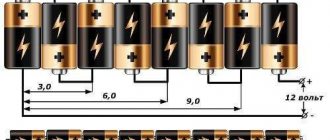
Standard voltage is the voltage that is very commonly used in your electronic gadgets. This voltage is 1.5 Volts, 3 Volts, 5 Volts, 9 Volts, 12 Volts, 24 Volts, etc. For example, your antediluvian MP3 player contained one 1.5 Volt battery. The TV remote control already uses two 1.5 Volt batteries connected in series, which means 3 Volts. In the USB connector, the outermost contacts have a potential of 5 Volts. Probably everyone had a Dandy in their childhood? To power Dandy, it was necessary to supply it with a voltage of 9 volts. Well, 12 Volts are used in almost all cars. 24 Volt is already used mainly in industry. Also, for this, relatively speaking, standard series, various consumers of this voltage are “sharpened”: light bulbs, record players, etc.
But, alas, our world is not ideal. Sometimes you just really need to get a voltage that is not from the standard range. For example, 9.6 Volts. Well, neither this way nor that... Yes, the power supply helps us out here. But again, if you use a ready-made power supply, then you will have to carry it along with the electronic trinket. How to solve this issue? So, I will give you three options:
Option #1
Make a voltage regulator in the electronic trinket circuit according to this scheme (in more detail):
Option No. 2
Build a stable source of non-standard voltage using three-terminal voltage stabilizers. Schemes to the studio!
What do we see as a result? We see a voltage stabilizer and a zener diode connected to the middle terminal of the stabilizer. XX are the last two digits written on the stabilizer.
There may be numbers 05, 09, 12, 15, 18, 24. There may already be even more than 24. I don’t know, I won’t lie. These last two digits tell us the voltage that the stabilizer will produce according to the classic connection scheme:
Here, the 7805 stabilizer gives us 5 Volts at the output according to this scheme. 7812 will produce 12 Volts, 7815 - 15 Volts. You can read more about stabilizers.
U of the zener diode
is the stabilization voltage on the zener diode.
If we take a zener diode with a stabilization voltage of 3 Volts and a voltage regulator 7805, then the output will be 8 Volts. 8 Volts is already a non-standard voltage range ;-). It turns out that by choosing the right stabilizer and the right zener diode, you can easily get a very stable voltage from a non-standard range of voltages ;-).
Let's look at all this with an example. Since I simply measure the voltage at the terminals of the stabilizer, I do not use capacitors. If I were powering the load, then I would also use capacitors. Our guinea pig is the 7805 stabilizer. We supply 9 Volts from the bulldozer to the input of this stabilizer:
Therefore, the output will be 5 Volts, after all, the stabilizer is 7805.
Now we take a zener diode for U stabilization = 2.4 Volts and insert it according to this circuit, it is possible without capacitors, after all, we are just measuring the voltage.
Oops, 7.3 Volts! 5+2.4 Volts. Works! Since my zener diodes are not high-precision (precision), the voltage of the zener diode may differ slightly from the nameplate (voltage declared by the manufacturer). Well, I think it's no problem. 0.1 Volt will not make a difference for us. As I already said, in this way you can select any value out of the ordinary.