The role of an ordinary switch, that is, breaking the circuit, is a secondary task of the circuit breaker.
And if you abuse frequent shutdowns using automatic machines, especially without disconnecting the load from the sockets, the contacts inside the automatic machine gradually burn out.
The contacts will eventually burn and blacken, losing their rated capacity. As a result, after some time, you will have to change the circuit breaker. If you do not do this, another short circuit may cause the machine itself to ignite.
Therefore, load switches were developed to improve the safety of electrical panels and the reliability of power supply.
A switch in the dashboard instead of a machine gun. What are the benefits and why should you know?
The role of a general switch in the electrical panel of a house or apartment can be played by either a machine or a switch. But it is recommended to install a switch in the panel instead of a machine, and why will be discussed further.
Comparison of switches and circuit breakers.
First, it’s worth understanding what both of these devices are. A switch differs from a circuit breaker only in that it does not have an automatic shutdown function. That is, you will have to turn off the switch manually. At first glance, it seems that this is a disadvantage and not an advantage, but you should not rush to conclusions. You need to know that there is no selectivity between the circuit breakers in the electrical panel - that is, all stages of protection are triggered in turn. If there was current selectivity with an input circuit breaker, and that with a circuit breaker located in the floor panel, in the event of a short circuit, only the group circuit breaker connected to this line would be turned off.
But practice shows that most often the general machine is turned off, not a separate one, and this is extremely inconvenient. The fact is that because of this, electricity is lost throughout the apartment. If there was a switch, it would only work where it was needed.
As for the machine located inside the floor panel, it is worth remembering the wire connecting the electrical panel in the house and the distant machine. Due to resistance and inductance, there will be some delay in the passage of current. This will allow the group machine to fire first, which is very convenient.
In addition to all this, a switch is considered more reliable than a circuit breaker. It is durable and can withstand repeated daily switching off and switching on. Even with intensive use, such an electrical device will last much longer than an automatic device. The reason for such reliability of the switch lies in the simplicity of its design: there is practically nothing in it except contacts. At the same time, it is quite powerful.
The difference between a switch and a machine
Unlike switches, automatic machines are characterized by a more complex design design, and they also have more responsibility: they protect the electrical circuit from short-circuit overcurrent and overload. The disadvantage of a circuit breaker is its limited service life, since it is designed for a certain number of on-off cycles.
Thus, if you need to regularly turn off the power supply, it is not recommended to use the machine - it is better to install a switch. In addition, switches are much cheaper than automatic switches.
Recommendation
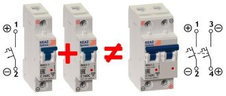
: Experts advise using 2 devices at once to enter the system. But why might you need to combine a switch with a circuit breaker? Using two devices
For maximum convenience of managing the electrical network, it is necessary to use both a switch and an automatic switch. Of course, if you don't plan on frequent power outages, you can get by with a simple circuit breaker. But the electrical network of apartment buildings, as well as industrial buildings, is characterized by increased requirements for electrical safety and operation. A switch is usually installed at the most critical place, which will play the role of a switching device, with the help of which it will be possible to manually de-energize the entire line. It is not recommended to use switches with protective covers, since the circuit break must be visible. This is necessary so that before starting electrical work, a specialist can visually verify that the circuit contacts are broken. However, if you use a machine with a closed case, it will be impossible to see the circuit break.
Also, the use of a switch is necessary in the workshops of manufacturing enterprises, where at the end of the working day it is necessary to de-energize all equipment or turn off the entire lighting system at once. But it is necessary to use a switch in conjunction with a circuit breaker so that the network is reliably protected from emergency situations such as overcurrents that occur during short circuits.
Let's sum it up
As you can see, the question of how to distinguish a robot from an automatic machine externally is complex. The fact is that to simplify interaction, manufacturers make all types of automatic transmissions similar to each other both in modes and in controls in the cabin.
Finally, we note that the use of automatic transmission is becoming very relevant in our time, since automatic transmission is convenient and safe, especially in big cities. However, each type of machine has both pros and cons.
At the same time, the robotic gearbox is not far behind the “classic” automatic gearbox in its popularity. First of all, such demand for manual transmission is due to popularization and cheaper production, which is reflected in the final cost of the car.
What is the difference between a CVT transmission and an automatic transmission or robot transmission: the main differences between CVT and automatic transmission, as well as robotic transmissions such as AMT or DSG.
How to use a robotic gearbox correctly: “single-disc” robot, preselective robotic gearbox with two clutches. Recommendations.
Automatic transmission AT or robotic automated transmission AMT: which gearbox is better, features of “automatic” and “robot”. Recommendations.
What is better to choose, an automatic transmission with a torque converter or a robotic gearbox with one or two clutches. Pros and cons of these types of boxes, recommendations.
What is the difference between a “classic” automatic transmission with a torque converter and a robotic gearbox with one clutch and preselective robots such as DSG.
Robot gearbox: what manual transmissions are there, the strengths and weaknesses of robotic gearboxes. What to consider when purchasing and operating a robot.
How does a switch differ from a machine, and in what circuits is it mounted?
What is the difference between a machine and a switch, when is the first used, and what is the second used for? What design features and types of these switching devices are there?
We will analyze all this in our article, and for this, first of all, we will consider the design of first the switch, and then the machine. Then we will dwell on issues related to the operating features of these switching devices and their areas of application. This will allow you not only to see the fundamental differences between these devices, but also to understand what this is connected with.
- Design of switch and machine Design of switch
- Machine design
Design of switch and machine
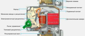
We will begin our conversation with the design and types of automatic machines and switches. This topic alone will allow you to understand their fundamental difference.
Switch design
At the moment, you can find a huge number of switches, both by purpose and by design. First, let's look at the design of the simplest switch, and then we'll look at the most popular modifications and types of switches.
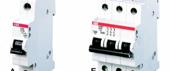
- The photo above shows a three-pole switch with the ability to simultaneously turn off all three poles. Some three-pole switches are designed with the ability to turn off each pole one by one. For our version, this would require removing the black connecting shaft and then each pole could be controlled separately.
Modular load switch or input circuit breaker? 4 advantages of use.
Surely many of you have used circuit breakers. There were no problems turning the lights on and off using such switches. But you should know that, first of all, circuit breakers were created not for frequent switching operations, but to protect electrical wiring and pantographs from overcurrents.
The role of an ordinary switch, that is, breaking the circuit, is a secondary task of the circuit breaker.
And if you abuse frequent shutdowns using automatic machines, especially without disconnecting the load from the sockets, the contacts inside the automatic machine gradually burn out.
The contacts will eventually burn and blacken, losing their rated capacity. As a result, after some time, you will have to change the circuit breaker. If you do not do this, another short circuit may cause the machine itself to ignite.
Therefore, load switches were developed to improve the safety of electrical panels and the reliability of power supply.
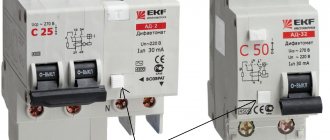
Modular switches ABB series SD200, E200 (from 16A to 125A)
SD200 modular switches from ABB
Currently, there are a very large number of mechanisms and devices that help the user manage and monitor power lines. One of the most common such devices are switches, which allow the user to disconnect the electrical circuit at any time.
ABB Campaign
, which is one of the leaders in the manufacture and sale of various types of electronic products, is developing innovative models of switches.
The result of their work was the release of the SD200 modular device, which is superior to its analogues in many respects. This switch is universal, and anyone can choose a specific version of the device for their needs. SD200 can be used both in production and at home. This became possible due to the large range of models, differing in the permissible operating range relative to the rated current (from 16A to 63A). SD200 switches
are a newer and modified device compared to the E200 module produced by ABB.
SD200 switches
can be characterized by these criteria:
1. The body of the switch is a one-piece structure that houses a very complex functional mechanism. Despite this, the user only has access to a lever protruding from the housing, which is made of plastic. This toggle switch controls the entire machine. When working with the device, the user does not come into contact with any of its components, which provides additional safety.
2. The shape of the switch is compact and has a beautiful appearance, so these devices can be installed even in a visible place. Also, an ABB engineer, using a special laser, engraved the body with brief technical characteristics of the switch and its serial designation. Such markings are wear-resistant and will not be erased from the body under prolonged mechanical impact.
3. The number of poles allowed in different models of SD200 devices can vary from 1 to 4.
4. The modular switch is mounted in electrical panels or on a flat surface. ABB has achieved versatility in its solutions in terms of accessories, due to which the user can use a single S200 series of various types of accessories. Accessories for switches help a person to carry out more complex installation of devices and provide them with additional functionality.
5. The material from which the SD200 switches are made is heat-resistant and not subject to combustion. In emergency situations or heavy loads, the switch may melt, but no fire will occur.
6. The wire is supplied and connected from both sides. Additionally, ABB employees have developed special terminals that allow the user to connect conductors with a conductor cross-section of up to 35 mm2. This has significantly expanded the range of applications for SD200 devices.
Operating the SD200 modular switch
the user can be confident in its reliability and trouble-free operation for a long time.
ABB series E200 - modular switch for DIN rail
Load switches
- this is something between a disconnector that does not allow load switching and a circuit breaker that cuts off the current during emergency conditions. The load switch is not designed to interrupt currents.
ABB is a Swedish-Swiss manufacturer of electrical equipment with more than 15 years of experience. Switches ABB
- these are special electrical devices with the help of which it is possible to non-automatically turn off the AC power circuit. Such switches are installed in switchboards, cabinets and other distribution devices or as main switches for equipment. The devices can also be used as emergency switches. Thus, a switch is an ordinary, but very powerful switch. The task of the circuit breaker is simply to turn off the power to a certain line.
For whom which type is best?
If, after reading this article, you are wondering which car with a transmission you should buy, then I will advise you the following:
- Automatic transmission is a good investment. This is a reliable, long-lasting friend of the car. With proper care, it will last more than 150,000 kilometers. DSG will not show such a service life. Moreover, the automatic machine can withstand parking in traffic jams and city traffic. The downside of the machine is the high price of a new box, although contract ones are cheaper, and expensive maintenance. But again, if a person operates the gearbox correctly, changes the oil on time, and does standard repairs, then the automatic transmission will last a long time;
- DSG is smoother when changing gears, consumes little fuel compared to an automatic. However, its resource is limited. If the automatic transmission can be tricked and it will travel for another 100,000 kilometers without additional investments, then the DSG will have to be immediately replaced with a new one or a contract one. DSG does not like idle time in traffic jams, constant speed reductions and speed increases in urban conditions. Therefore, it is better to use a robot when you often travel long distances. Here he shows his best side.
vote
Article rating
Switches
- difference between a switch and a disconnector;
- selecting a switch series according to its parameters.
Definition
A switch is a device for turning on, switching and disconnecting current with a power of 100 amperes and above. Hence there are two types:
- breaking switch – turns on and off (has 2 positions);
- reversing or changeover switch - turns on the main power, turns off and turns on the backup power (has 3 positions; for example, turns on the power from the OblEnergo network, turns it off and turns on the power from the generator).
- disconnector;
- load switch;
- switch-disconnector (combines the functions of the first two).
often called a switch.
Functions of a disconnector, load switch and switch-disconnector, their differences
The main task is to manually turn on, turn off and switch the power supply; the contacts are transferred using the operator’s muscle strength.
Additional tasks (extracted from the international standard GOST 50030 part 3 according to definitions 2.1 and 2.2):
- for a disconnector - disconnection of the electrical system, that is, between the separated moving and fixed contacts there is a standardized air space (more details in paragraph 7.1.6 of the GOST 50030 part 1 standard), which eliminates breakdown (this is necessary for safe repairs or inspection of the network);
- for a circuit breaker - turning off the power to a loaded electrical system, that is, current consumers are working, the operator opens the contacts, an electric arc forms between them and goes out in the arc-extinguishing chambers (this device has chambers for each pole);
- for a switch-disconnector – eliminates breakdown and extinguishes the arc (connects both devices).
- the disconnector does not turn off the loaded network (next to the handle there should be an inscription: “Do not turn off under load”), while it can turn off minor currents (listed on page 5 in definition No. 22 of the GOST 17703-72 standard): currents of instrumentation;
- leakage currents;
- capacitive currents of short conductors and output buses;
- transformer no-load currents;
- a large solution between the moving and fixed contacts in the off position;
- or double circuit break.
Naturally, if a fire occurs, in order to save property and people’s lives, the disconnector handle will be “pulled” and the system will be de-energized, but the device will fail (the arc will burn out the copper).
CS-CS.Net: Laboratory of the Electroshaman
Switches (disconnectors) ABB E200 and OT series
And again I delight you with fresh posts after some lull. The lull was caused by the fact that I was actively burning: coming up with new ideas, kicking orders, working in the fields (assembling shields and connecting some of the old orders together with my Partner).
Attention! Since the fall of 2015, the E200 series of circuit breakers has finally been discontinued! Instead, there are already new switches of the SD200 series. Read the post about them and DO NOT use the E200 series. And if you see a project that still says E20x - KILL the designer, don’t pay him money, because he DOES NOT know anything at all and does not know how to make projects!
This post has been brewing for a long time, and perfectly coincided with several questions that fell on me in a row: “Why are you insistently declaring here that a switch is needed! Yes, I’ll put a machine gun in his place and okay, why are you arguing?” and questions like “Why is a switch better than a machine and where should I put what?” To answer them, I’m writing this post because the housing of one of the switches very successfully broke, and I decided to take it apart and take a photo. And to make it more interesting, I bought a cheap switch of a different series (OT25) and also broke it and took a photo. Let's go read!
So, first the theoretical part. A switch (or power disconnector) is a regular switch, but powerful. The task of the switch is simply to turn off the power to some line. That's what they are used for. Actually, the explanation could end there. But no =) We will apply it to our shields and our work, and describe it in more detail =)
So, here's where the switch can be useful. Firstly, on the input. Because the PUE literally says that there must be some kind of switching device in front of the meter that can be used to de-energize the meter in order to replace/verify it. In some cases, the role of the switch can be played by an introductory machine, and in some cases it will be more convenient to install the switch first, and then, after the meter, the machine.
Secondly, the switch is technically simpler: there is nothing there except contacts. This means that it is more reliable than a machine, which also has all sorts of current releases. And similarly, at critical places on the input cable coming from the substation/input, it is best to first install a switch: turn it off and change what you want and how you want.
Thirdly, in some cases, for example, when using non-switchable lines, we need a switch to turn off the power to the panel. Another good practice is to start the panel with a switch: there will be somewhere to run the power cable.
I am often asked whether it is necessary to break the zero with a switch at the input to the switchboard . Many are afraid that this is a zero - what if it turns on later than the phases or does not turn on at all, and the switch will cause a “zero burnout” inside the shield.
I always break the zero at the input in the switchboard with a switch and here's why. Firstly, in domestic construction (houses, cottages) we are often forced to use the “TT” grounding system (I remind you of the post about bushings), in which, in the event of various accidents, anything can fly to the neutral wire - even a phase. If the switch breaks zero, then it will completely protect you from such accidents. Secondly, if we talk about the assembly of switchboards, then the zero on the switch gives us a convenient point for connecting the input cable, intuitively understandable: Ground (PE) - to the busbar, and everything else - to one place on the switchboard, to the main input switch.
to NOT break the zero with a switch in one case: if you are making a control panel/ASU for a TN-CS grounding system, in which the input zero is considered a PEN conductor, and this PEN conductor must under no circumstances be disconnected, but must be immediately connected to grounding bus.
If you are concerned that the zero of the switch may fall off or turn on later, then special additional poles are produced especially for you in OT switches, which are turned on first and turned off last. I install the usual zero poles OTPS80FP (for OT switches of 63 and 80A) or OTPS125FP (for OT switches of 100 and 125A), and over all the years of assembling panels, only one pole turned out to be defective - it simply did not turn on.
In modular switches SD200 (and old E200), the delay between turning on zero and phases is small, and the equipment does not have time to notice it. And for those who are completely paranoid, I remind you that now all switchboards have a voltage relay at the input. So if there are problems with the zero in the input switch, then these relays will save us.
Some Kulibins use a high-denomination machine as a switch. Let's say, with an introductory voltage of 25A, they set the machine to 63 and rejoice. And some duplicate the input machine in the floor panel and in the apartment panel. This is all you don’t need to do! There should be ONE input machine - where it belongs. If it is located in the floor panel, put a switch in the apartment!
Well, now let's move on from vague words to action. So, ABB has two series of switches left. These are E200 and OT . The latest series is replacing E200 , and it is best to use it. Let me describe the brief features of these series.
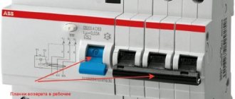
E200 series are simple modular switches in automatic format. The handle can be of two colors: red and gray. There are from one to 4 poles. They look rather flimsy and are now made in Bulgaria. They can't do anything other than turn it on and off. Their advantage is the minimum space they occupy in panels ( OT with less than 3 poles in principle do not exist) and the ease of switching: even the weakest fingers can handle it.
They are designated simply and bluntly: E20<number of poles><handle color: r - red; g - gray>. That is, E202r 63 means a two-pole switch with a red handle for a current of up to 63 amperes. By the way, this is my warehouse item - a popular product that I put in my shields.
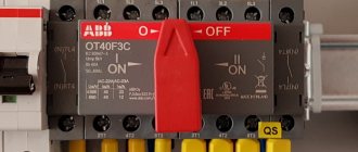
OT series switches have a much wider range of capabilities and do not have an easily described standard designation. But they have an infernal mechanism that snaps them sharply, preventing the formation of an arc between the contacts at the moment of switching on and off. They have a bunch of accessories in the form of additional poles (you can, for example, create a five-pole switch from a regular three-pole one), types of handles (for a switch, for a switchboard, for a cabinet) and are even immediately available in a waterproof case so that, for example, you can put it on the wall of a house . They can also be reversible (with positions I-0-II), and they can be used to switch power from the Network to the Generator, organize a bypass for the stabilizer/UPS and other similar things.
This is their downside (for us). Firstly, only a person with strong fingers can switch it. Some sweet and gentle woman - no. And they also come with at least three poles, eating up the extra modules of the single-phase shield.
This is how I make my choice of episodes. If the shield is single-phase, budget, or for small currents (up to 40A), then I install E202r 63. If the shield will be used with a higher rating of the input circuit breaker (40-50-63A) or three-phase, then I install an OT63F3 (three-pole for 63A ). And if there is a need to break 4 poles, I order 4-pole switches. And reversible ones too if necessary.
I always take the current from the switches to 63A. This is the most popular position of all warehouses, and it also allows, in case of a shortage of materials, to quickly take switches from stock. Let’s say, if I’m assembling two panels, and both have switches for 63A (despite the fact that one panel is for the input circuit breaker at 25A, and the other is for 40A), then if only one arrived, I urgently need to assemble another panel (holding the first ) - you can do this easily, because the position is the same.
Here are some switches lying around my house:
Types of terminals for E200 and OT series disconnectors
The leftmost one, as you understand, is E202r 63 , then OT25E3 , and then OT63F3 . 63rd is for ordering, so we won’t disassemble it. But we’re dissecting the first two, because it’s interesting to find out what’s inside. In principle, when you take the switches in your hands, you can immediately see that the OT series is harsh. It seems that it was designed by harsh Chelyabinsk residents. And it is better thought out, of course. To the point that all the designations and operational data are written on the switch, and on the box there is a drawing of holes for attaching the switch to the mounting panel (we cut out cardboard from the box with scissors, attached it, and marked the holes).
Marking of switch ABB OT63F3
We start with a simple patient. There were rumors on the MasterCity forums that these switches break the pole in two places, and as such they do not have a moving contact.
Here, perhaps, it is necessary to say a few words about moving and stationary contact. Historically, the switch, as I tried to write above, was used to create a line break visible to the eye. That is, the stern man turned the handle, the contacts moved away, and he saw it with his eyes. Usually the switch was made like this: some contacts were stationary, while others moved and came into contact with them.
And then people thought of it with their heads and decided to make switches like this. They placed a fixed contact on top, and a movable one on the bottom. And they supplied the incoming power to a fixed contact. The essence of all these manipulations is safety: if something breaks in the mechanics, then the fixed contact, which is under voltage, will remain as it was with a greater probability than the moving one. And let the moving one fall anywhere =)
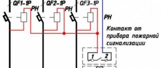
Actually, if you look carefully at the diagram drawn on a machine, switch or something else, then usually the upper contacts are fixed, and the lower ones are movable (header photo). This is where the legs of the rule “incoming food always comes from above” grow.
So, take a drill and boldly drill out all the rivets:
We prepare the switch E202r 63: we drill out the rivets
...and we discover that these switches are made up of single modules with rivets. And since the body of this switch was cracked at only one of the poles, now I have a single-pole 63 ampere switch. Someone like a neighbor needs to put it in a shield
A two-pole switch consists of two separate
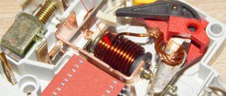
Open the case and LAM! The design is HARD =) But the most interesting thing is the complete discrepancy with the diagram! In the photo above you can see that the switch is turned off. Lever down. It is shown that the upper contacts are stationary. Now look at the photo below. There's a lever at the bottom too. That is, the right contact in the photo is the top one. And what? It's the other way around! He's mobile. Gee gee gee gee gee =))
Internals of the E200 switch: moving and fixed contact
Here you can take a closer look at the entire mechanism when it is turned on:
Internals of the switch (switch on)
In general, I laughed a lot at these switches. I was skeptical about them before, but now it’s even more fun. But on the other hand, not everything is so bad as to cause panic: “Oh, the E200 is crap, and change them all urgently.” As I wrote above, I use them in switchboards (and will use them) if the shield is used by personnel with weak fingers, and if in the shield you have to fight for each module, and the input allows you to install such a switch with a current reserve.
But the OT series was more fun. If with the E200 it was dangerous not to break the switch itself with an awkward movement, then when disassembling the OT series it was dangerous not to break your fingers or get hit in the eye by a spring. Now you will find out why. At a minimum, because these switches are produced by hot Finnish guys, apparently on the advice of tough Chelyabinsk men. Because there was no way to disassemble it so easily. I thought that now, oops, I’ll pry a couple of latches with a screwdriver and it will open.
Yeah, SCHAZ! I didn't find any latches at all. And only wire cutters with pobedit tips helped me. Which, after five minutes of torture and swearing, they managed to somehow scratch and break a corner of the body.
Attempt to break OT25 failed =)
Then things moved on... still with difficulty! =) Oh, ABB people probably have hiccups and their hearts bleed when they see their mega-products being broken!
Somehow, by biting the case, I managed to open the drive mechanism. And here - only respects. Actually, again a piece of theory. The fact is that the switch can also be turned off under load. How did they write there?
At 11:18 a.m. Moscow time, Vasily Petrovich Chuichenko, the chief power engineer of the Southwestern District, lowered the switch handle with an unwavering hand, leaving two dozen houses without power. Among them was the house where the Server stood.
© Black Moderator
So, if you do it as described in the text, then when the switch is turned off under load, a huge (or not so huge) arc will appear. In some cases, such an arc can even be maintained by itself until everything around it burns out (let’s look at the video clips from a hundred years ago). The video, of course, gives an example for a high-voltage line. In our 220/380 you can expect a powerful spark. And in order to reduce the risk of its formation when the switch is turned off, the switch must be turned off sharply.
In the case of the E200, all hope lies in man. If he turns it off with a normal movement, everything will be fine. If you slowly and thoughtfully take a teaspoon per hour, there is a chance of getting an arc on the contacts.
In the OT series, people thought and made a cunning drive: a person rotates an uneven shaped cam. On one side it protrudes more, on the other - less. And with this protrusion the cam presses on the rod, which, in turn, moves the contacts. And in order for the cam to rotate jerkily, it is equipped with a spring. And to make it SEVERE - there are already 4 springs! I say: it couldn’t have happened without Chelyabinsk, obviously!
Mechanism of operation of OT series switches
This is how this cam is placed and presses on the white rod =)
Mechanism operation: the cam, turning, presses on the contact rod
This is how the cable clamps are designed. In the 25-amp version, these are simply flattened plates that press the cable. In the 63 amp version, the clamps are more brutal and have a larger clamping area. Pay attention to this little detail: the place where the thread for the screw is cut has a thickening so that even a drunken ZhEK electrician will not tear off this thread if he ever has to install such a switch. Well, there is no need to talk about the fact that all the screws do not fall out.
One of the terminals of the 25A OT switch
Let's open the switch further and check out the contact groups. Actually, everything can be seen this way. Contactors/starters probably have this contact design. When each contact is also spring-loaded. Well, breaking the chain here is done like an adult: on both sides, and all external contacts are stationary. You can serve whatever you want, however you like.
Switch contact group ABB OT25
You don't even need to draw conclusions. If you want non-standard functions (reversing switch, etc.), this is definitely the OT series. If you want an evil switch that can be turned 50 times a day and also under load, this is also the OT series.
But if you are assembling a small shield for a frail input, and every module is important to you (this also happens), then you can install the E200. And if a housewife will use the shield, also look towards the E200. But the statistics are inexorable: approximately one switch out of 15 may be defective.
And I’ll also say a few words about the reversing switches of the OT series . I have nowhere to take a special photo of it right now, so I’ll give you links to my own photos of the shields.
, here they are in Igor Valentinovich’s window
and here they are in the mega-shield for the cottage:
.
A reversing switch is a switch from one position to another. They are usually used to switch power supplies. Say, from one input to another or from the network to a generator. The only difference is that for safety and to completely turn off the line, there is a third position when no input is selected.
Mnemonically, this can be written as follows: I-OFF-II. And in theory, such switches should have three groups of contacts: General, I and II. But in the OT series we are faced with a feature that causes a brain explosion in uninitiated people accustomed to standard switches. In the OT series, the reversing switch consists of two conventional switches placed side by side and connected by a special drive. The drive has three positions (the same I-OFF-II) and controls these two switches. In position “I” only the left switch is turned on. In position “II” - only the right one. And as such, they do not have a common contact, and you need to make it yourself by connecting the switches on one of the sides in parallel.
The photo clearly shows how it was done. Here this switch switches the power between the generator and the mains. The network and the generator are connected to the upper contacts of two circuit breakers of the assembly, and the lower contacts are connected in parallel. And so that the circuit is universal, and it is possible to connect not a generator (maybe it is not needed), but a stabilizer or UPS, then two blocks of terminal blocks are made. One is to the switch, the second is to switch “II”. We will supply power before the switch to the stabilizer/UPS, and to switch “II” we will supply clean power. And then the same switch works for us as a correct and high-quality bypass, without any fuss.
I especially note an important point! Reversible switches take up twice as much space in height and come without a handle included!! When choosing a shield for them, BE CAREFUL! They won’t fit into regular Europa/Uniboxes: the panel door won’t close! I haven’t tested it in UK500, but they fit in Europa IP65 and AT/U without any problems!
In order not to climb through catalogues, I give information for reference (my popular items):
1SCA105338R1001 ABB OT63F3C Reversing switch up to 63A 3-pole (without handle) 1SCA108319R1001 ABB OHBS3/1 Control handle (black) direct mounting for switches OT16..125F 1SCA108688R1001 ABB OHRS3/1 Control handle (red naya) direct mounting for circuit breakers OT16..125F
That's all. Let's move on! =)
UPDATE : There is one more addition that I forgot about, but they reminded me: it is also important that switches with a nominal value of 16, 25, 40A have a height less than the height of the panel and, if you put them in a regular panel on a DIN rail, then they will be located somewhere inside the shield and will be completely inconvenient to use. Therefore, the most convenient rating is 63A switches, which fit perfectly into the panel.
Examples of fuse applications
RU, electrical panels
High-voltage fuses for 100A of the input cell of a transformer 10/0.4 kV 1 MVA
Industrial equipment
Three pole fuse holder 100A 120kA
Here, when any of the three fuses trip, the emergency circuit breaks and everything stops:
Fast-acting fuses with auxiliary contacts
The topic of fuses is vast and multifaceted. I did not provide even a percentage of all the information. But I hope this article answered some questions.
I also recommend an article about power industrial machines in a molded case. The article provides an example of installation and an overview of the main parameters of power circuit breakers.