Before we begin the practical connection of the starter, let us recall a useful theory: the contactor of the magnetic starter is turned on by a control pulse emanating from pressing the start button, which supplies voltage to the control coil. Keeping the contactor in the on state occurs according to the self-retaining principle - when an additional contact is connected in parallel with the start button, thereby supplying voltage to the coil, as a result of which there is no need to hold the start button pressed.
Disabling the magnetic starter in this case is possible only if the control coil circuit is broken, which makes it obvious that it is necessary to use a button with a break contact. Therefore, the starter control buttons, which are called push-button posts, have two pairs of contacts - normally open (open, normally closed, NO, NO) and normally closed (closed, normally closed, NC, NC)
This universalization of all the buttons of the push-button station was made in order to anticipate possible schemes for providing instant engine reverse. It is generally accepted to call the shutdown button the word: “ Stop ” and mark it in red. The turning button is often called the start button, start button, or is designated by the words “ Start ”, “ Forward ”, “ Back ”.
If the coil is designed to operate from 220 V, then the control circuit switches the neutral. If the operating voltage of the electromagnetic coil is 380 V, then a current flows in the control circuit, “removed” from the other supply terminal of the starter.
Connection diagram for a 220 V magnetic starter
Here, the current is supplied to the magnetic coil KM 1 through a thermal relay and terminals connected in a chain of buttons SB2 for turning on - “start” and SB1 for stopping - “stop”. When we press “start”, electric current flows to the coil. At the same time, the starter core attracts the armature, resulting in the closure of the moving power contacts, after which voltage is supplied to the load. When “start” is released, the circuit does not open, since the KM1 block contact with closed magnetic contacts is connected parallel to this button. Thanks to this, phase voltage L3 is supplied to the coil. When you press “stop,” the power is turned off, the moving contacts return to their original position, which leads to de-energization of the load. The same processes occur when the thermal relay P operates - a break in the zero N supplying the coil is ensured.
Contactors and starters - what's the difference?
When the voltage drops, the electromagnetic field also disappears, the springs push the moving part of the magnetic circuit up, and the contacts return to their original state. Only the assembly of the contact group differs - all three phases are connected.
A return spring keeps them in this state. As a result, the spring easily pushes out the upper part of the magnetic circuit, opening the contacts, which leads to the cessation of power supply to the load. For example, for the operation of a winch, in some other cases.
Nothing complicated either. Contactors, in most cases, do not have a housing, therefore they must be installed in protective housings or boxes that will protect against accidental contact with live parts, as well as from rain and dust.
This allows, among other things, to significantly reduce the consumed starting currents. This algorithm is implemented by closing auxiliary contacts in the MP.
Related article: Energy efficiency passport of a building
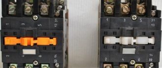
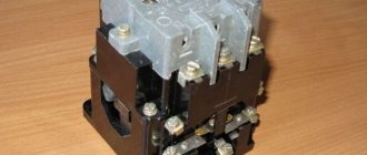
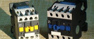
Visual diagrams of MP and CM
Therefore, a so-called self-catching circuit is added to the circuit. When the force on it is B, motor B, in the case of a star connection, such a scheme is not suitable. Features of the power circuit Power for the MP is connected through contacts, usually designated by the symbols A1 and A2. For low currents - up to 10 A - only starters are produced.
Any voltage can be applied to the contacts and connected to them - either constant or alternating. Only it added a thermal relay that will protect the engine from overheating. Even most often, the phase is supplied to A2, since for convenience this contact is located on the bottom side of the housing. To twist in the opposite direction, you only need to use the KM2 starter to change the dislocation of some two supply phases. The action taken will disconnect the circuit, the control phase A will no longer be supplied to the KM1 inductor, and the core with contacts, by means of a return spring, will be restored to its original position. There is also usually a ground terminal.
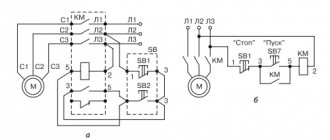
Connecting the starter according to the star-delta scheme
The contacts will disconnect and the voltage supply to the motor M will stop. If they are stranded, their ends are twisted before tinning. From this it can be seen that the starter and contactor are controlled by applying and cutting off voltage to their electromagnetic coil. This creates an electrical interlock that prevents two contactors from being supplied with power at the same time. But since a similar operating algorithm is suitable for many devices, a wide variety of devices are connected through them - lighting circuits, various devices and devices.
For example, for the operation of a winch, in some other cases. For example, for a 4kW motor, you can install a 10A automatic. For example, the PKI prefix. It is strictly forbidden to supply a current of a higher voltage or strength to the outputs than indicated in the marking. The buttons are labeled with a name and color. A simple diagram of an electromagnetic starter - what it is, how it works, what it consists of.
Connection diagram for a 380 V magnetic starter
Connecting to 380 V is practically no different from the first option, the only difference is in the supply voltage of the magnetic coil. In this case, power is provided using two phases L2 and L3, whereas in the first case - L3 and zero.
The diagram shows that the starter coil (5) is powered from phases L1 and L2 at a voltage of 380 V. Phase L1 is connected directly to it, and phase L2 is connected through button 2 “stop”, button 6 “start” and button 4 of the thermal relay, connected in series to each other. The principle of operation of such a circuit is as follows: After pressing the “start” button 6, through the switched on button 4 of the thermal relay, the voltage of phase L2 reaches the coil of the magnetic starter 5. The core is retracted, closing the contact group 7 to a certain load (electric motor M), and current is supplied, voltage 380 V. If the “start” is turned off, the circuit is not interrupted, the current passes through contact 3 - a movable block that closes when the core is retracted.
In the event of an accident, thermal relay 1 must be activated, its contact 4 is broken, the coil is turned off and the return springs bring the core to its original position. The contact group opens, relieving the voltage from the emergency area.
Advantages of implementing such a connection scheme
- The switch and control manipulator (button) can be separated. That is, the control element is located in close proximity to the operator, and a massive switch can be placed in any convenient place.
- It can be controlled using a foot drive (hands remain free). This allows for better control of the electrical installation and for holding the workpiece.
- The remote starter connection diagram allows you to place safety devices. For example, short circuit protection or thermal relays that are triggered by temperature overloads. In addition, this scheme makes it possible to implement mechanical protection: when the moving parts of the electrical installation move to a critical point, the limit switch is triggered and the magnetic starter opens.
- The remote location of the control elements allows the emergency button to be located in a convenient location, which increases operational safety.
- It is possible to install a single push-button station to control a large number of magnetic starters when electrical installations are located in different places and at great distances. The connection diagram through such a post involves the use of low-current control wiring, which saves money on the purchase of expensive power cables.
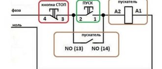
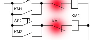
- To control one starter, you can install several push-button stations. In this case, control of the electrical installation from each post will be equivalent. That is, you can start the electric motor from one point and turn it off from another. Connection diagram for several push-button posts in the illustration:
- Magnetic contactors can be integrated into an electronic control system. In this case, commands to start and shut down electrical installations are given automatically, according to a given algorithm. It is impossible to organize such a system using mechanical (manual) switches.
In fact, such switching is a relay circuit.
Connecting a magnetic starter via a push-button post
This circuit includes additional start and stop buttons. Both “Stop” buttons are connected in the control circuit in series, and the “Start” buttons are connected in parallel. This connection allows switching with buttons from any position.
Here's another option. The circuit consists of a two-button post “Start” and “Stop” with two pairs of contacts, normally closed and open. Magnetic starter with a control coil for 220 V. The power supply for the buttons is taken from the terminal of the power contacts of the starter, number 1. The voltage approaches the “Stop” button, number 2. It passes through a normally closed contact, along the jumper to the “Start” button, number 3.
Functionality
Below are typical functions performed by magnetic starters, which are far from exhaustive of their applications:
- Control of asynchronous electric motors in drives of industrial mechanisms.
- Turning on external (street) city lighting, external and internal lighting of industrial facilities.
- Switching of electric heating devices (heating elements or infrared heaters) of electric heating systems.
- Use as triggers in industrial automation circuits.
The choice of magnetic starters is made when designing control and automation circuits, or during their repair, when to replace an outdated or missing device it is necessary to select its analogue.
Connecting the motor via starters
Irreversible magnetic starter
If it is not necessary to change the direction of rotation of the engine, then the control circuit uses two non-fixed spring-loaded buttons: one in the normal position is open - “Start”, the other is closed - “Stop”. As a rule, they are manufactured in a single dielectric housing, and one of them is red. Such buttons usually have two pairs of contact groups - one normally open, the other closed. Their type is determined during installation work visually or using a measuring device.
The control circuit wire is connected to the first terminal of the closed contacts of the Stop button. Two wires are connected to the second terminal of this button: one goes to any of the closest open contacts of the “Start” button, the second is connected to the control contact on the magnetic starter, which is open when the coil is turned off. This open contact is connected by a short wire to the controlled terminal of the coil.
The second wire from the “Start” button is connected directly to the terminal of the retractor coil. Thus, two wires must be connected to the controlled “pull-in” terminal – “direct” and “blocking”.
At the same time, the control contact closes and, thanks to the closed “Stop” button, the control action on the retractor coil is fixed. When the Start button is released, the magnetic starter remains closed. Opening the contacts of the “Stop” button causes the electromagnetic coil to be disconnected from the phase or neutral and the electric motor is turned off.
Reversing magnetic starter
To reverse the motor, two magnetic starters and three control buttons are required. Magnetic starters are installed next to each other. For greater clarity, let’s conditionally mark their supply terminals as 1–3–5, and those to which the motor is connected as 2–4–6.
For a reversible control circuit, the starters are connected as follows: terminals 1, 3 and 5 with the corresponding numbers of the adjacent starter. And the “output” contacts are crosswise: 2 from 6, 4 from 4, 6 from 2. The wire feeding the electric motor is connected to three terminals 2, 4, 6 of any starter.
With a cross connection scheme, simultaneous operation of both starters will result in a short circuit. Therefore, the conductor of the “blocking” circuit of each starter must first pass through the closed control contact of the adjacent one, and then through the open one of its own. Then turning on the second starter will cause the first one to turn off and vice versa.
Not two, but three wires are connected to the second terminal of the closed “Stop” button: two “blocking” and one supplying the “Start” button, connected in parallel to each other. With this connection scheme, the “Stop” button turns off any of the connected starters and stops the electric motor.
Installation Tips and Tricks
- Before assembling the circuit, you need to free the working area from the current and check that there is no voltage with a tester.
- Set the core voltage designation which is mentioned on it and not on the starter. It can be 220 or 380 volts. If it is 220 V, phase and zero go to the coil. Voltage marked 380 means different phases. This is an important aspect, because if connected incorrectly, the core may burn out or will not fully start the necessary contactors.
- Starter button (red) You need to take one red “Stop” button with closed contacts and one black or green button with the inscription “Start” with invariably open contacts.
- Please note that power contactors only force or stop the phases, and the zeros that come and go, conductors with grounding are always combined at the terminal block, bypassing the starter. To connect a 220 Volt core to the addition, 0 is taken from the terminal block into the design of the starter organization.
You will also need a useful device - an electrician's tester, which you can easily make yourself.
The article details several ways to update the BIOS on an Asus motherboard.
Now you can definitely choose the ideal laptop for work or study!
This article describes the benefits of SSD drives for applications and games. There is also a comparison between the advantages of this drive with its outdated counterpart.
Instructions - connecting a magnetic starter via a button
Let's look at the procedure for connecting a magnetic starter using the example of lighting control - turning on/off a regular lamp.
To do this you will need the following tools, devices and materials:
- magnetic switch;
- magnetic starter power button Start (it can be of two types - green or black);
- Stop button (red);
- installation box for buttons;
- two-core copper wire;
- socket with lamp;
- side cutters, knife, Phillips screwdriver.
To connect a push-button switch circuit, you need to do the following:
- From the “plus” power is supplied to the Stop button and from it a wire is output to the power contact of our magnetic starter;
- The output from the Stop button goes to the Start button and from it a “plus” is output to the auxiliary contact of the device, designated as 1L1;
- The second output from the Start button goes to the base contact of the starter A1;
- A jumper is connected to A1 from the 2T1 contact socket. This is necessary so that after releasing the “Start” button, the circuit does not open, and the phase continues to flow to the coil of the magnetic starter and self-holding is triggered when the start button is pressed once. Otherwise, for the device to operate, you will have to constantly keep the start button pressed;
- The negative wire goes straight to connector A2, as well as to 5L3;
- The controlled electrical device itself (in our case, a lamp) is connected to connectors 4T2 and 6L3.
IMPORTANT! Before connecting the electric motor, you must make sure that the connection diagram of the electric motor windings is correct in accordance with its passport data.
Symbols on diagrams
A magnetic starter (hereinafter referred to as the starter) is a switching device designed to start and stop the engine. The starter is controlled through an electric coil, which acts as an electromagnet; when voltage is applied to the coil, it acts with an electromagnetic field on the movable contacts of the starter, which close and turn on the electrical circuit, and vice versa, when the voltage is removed from the starter coil, the electromagnetic field disappears and the starter contacts are under the action of the spring returns to its original position, breaking the circuit.
Starter connection diagram
This is a simple starter circuit (a lightweight version), which is the basis of all, or at least most, starting circuits for asynchronous electric motors, which are used very widely, both in industry and in everyday life.
A bad electrician is one who does not know this circuit (surprisingly, there are such people). Although you may naturally understand the principle of its operation, to refresh your memory or for beginners, I will still briefly describe this work. And so, the entire circuit, not counting the electric motor, which is installed specifically on a specific equipment or device, is installed either in a panel or in a special box (PML).
The START and STOP buttons can be located either on the front side of this panel or not (installed in a place where it is convenient to control the work), or maybe both, depending on convenience. Three-phase voltage is supplied to this panel from the nearest power supply point (usually from a distribution board), and from it a cable goes to the electric motor itself.
Light starter circuit
note
And now about the operating mechanism: three-phase voltage is supplied to terminals F1, F2, F3. To start an asynchronous electric motor, the magnetic starter (PM) requires activation and the closure of its contacts PM1, PM2 and PM3.
To trigger the PM, you need to apply voltage to its winding (by the way, its value depends on the coil itself, in other words, what specific voltage it is designed for. This also depends on the conditions and place of operation of the equipment.
They come in 380V, 220V, 110V, 36V, 24V and 12V) (this circuit is designed for 220V voltage, as it is taken from one of the available phases and zero).
Power supply to the coil of the magnetic starter is carried out through the following circuit: From f1, the phase enters the closed thermal protection contact of the electric motor TP1, then passes through the coil of the starter itself and goes to the Start button (KN1) and to the self-retaining contact PM4 (magnetic starter). Their power goes to the normally closed STOP button and then closes to zero.
To start, you need to press the “Start” button, after which the circuit of the magnetic starter coil will close and attract (close) contacts PM1-3 (to start the motor) and contact PM4, which will make it possible, when the start button is released, to continue working and not turn off the magnetic starter ( called self-recovery). To stop the electric motor, you just need to press the STOP button (KN2) and thereby break the power supply circuit of the PM coil. As a result, contacts PM1-3 and PM4 will turn off, and operation will be stopped until the next start of the Startup.
For protection, thermal relays must be installed (in our diagram this is a TP). When the electric motor is overloaded, the current increases accordingly, and the engine suddenly begins to heat up, right to the point of failure. This protection is triggered specifically when the current in the phases increases, thereby opening its contacts TP1, which is similar to pressing the STOP button.
These cases occur mainly when the mechanical part is completely jammed or when there is a large mechanical overload in the equipment on which the electric motor operates.
Although it is not uncommon for the engine itself to become a prerequisite, due to dried out bearings, poor winding, mechanical damage, etc.
Important
I think for those who didn’t know this, this article: Starter circuit, lightweight version, was very useful and at some point will be needed more than once in life.
Starter connections according to the diagram - reverse
A variant of the above circuit is used to start electric motors operating in the same mode, i.e. without changing rotation (pumps, circular motors, fans). But for equipment that must work in 2 directions, such as a crane - beams, hoists, winches, opening and closing gates, etc., a different electrical circuit is needed.
For such a scheme, we will need not one, but two similar starters and a 3-button START-STOP button, i.e. two Start buttons and one STOP. In reverse circuits, remote controls with two buttons can also be used; these are areas where operating intervals are very short.
For example, a small winch, operating intervals of 3-10 seconds, for the operation of this equipment, the option with two buttons is more suitable, but both buttons are start buttons, i.e.
only with normally open contacts, and in the circuit the block contacts (pm1 and pm2) of self-retaining are not activated, and specifically, as long as you hold the button pressed, the equipment works, as if you released it, the equipment slowed down. Otherwise, the reverse circuit is similar to the lightweight version.
Starter connections according to the reverse diagram
Star-delta starter
Switching the motor from star to delta is used to protect electrical circuits from overloads. Basically, large three-phase asynchronous motors from 30-50 kW, and high-speed ones ~3000 rpm, and from time to time 1500 rpm, are switched from star to delta.
If the engine is connected in a star, then a voltage of 220 Volts is supplied to each of its windings, and if the engine is connected in a triangle, then a voltage of 380 Volts is supplied to each of its windings. Here Ohm’s law “I=U/R” comes into play; the higher the voltage, the higher the current, but the resistance does not change.
Simply put, when connected to a delta (380), the current will be higher than when connected to a star (220).
When the electric motor accelerates and gains full speed, the picture completely changes. The fact is that the engine has power that does not depend on whether it is connected to a star or a delta. The power of the motor depends mainly on the iron and the cross-section of the wire. Another law of electrical engineering “W=I*U” applies here.