To correctly connect powerful loads, a 220V electromagnetic starter is used. The special design ensures synchronous closure of contact groups and interruption of power circuits of similar quality. Unlike classic switches, it is permissible to use remote start and perform protective functions using a thermal relay.
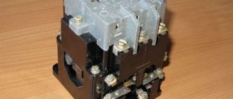
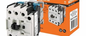
Typical electromagnetic starters
Application area
Electromagnetic starter 380V (220V) is used to connect:
- machine electric motor;
- Heating element of the melting furnace;
- lighting (heating) systems;
- duct fan;
- conveyor belt drive.
Many examples can be given. However, this list is enough to understand the intended purpose - supplying power to a powerful load. This means working with fairly high currents at standard mains voltages, 220V or 380V, respectively.
Magnetic starter design
Magnetic starter PML
The picture below shows the components of a typical starter. The stationary lower part, when the coil is connected to the power supply, forms an electromagnetic field that attracts the moving element. The contacts connected to the armature close the operating circuit. If the winding is de-energized, the spring will return the system to its original state.
Main functional elements of the starter
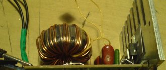
The core of the electromagnet is assembled from plates in the shape of the letter “W”. A large number of components block parasitic currents (skin effect). The number of turns is selected taking into account the supply voltage.
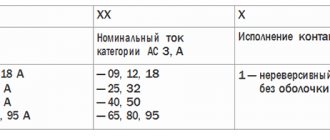
Sectors with designations
Explanatory inscriptions on the body are divided into three groups:
- general information and scope (AS1-4);
- information about permissible currents in load circuits (conversion to kW or reverse is performed taking into account the mains voltage);
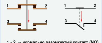
- graphic designation of contact groups (the broken line indicates synchronous switching).
Each area can be explored in detail. To familiarize yourself with the classification by purpose categories, follow the standards of GOST R 50030.4.1.-2002. The designation AC1 indicates the possibility of connecting the starter to heating elements, incandescent lamps and other loads with weakly expressed reactive characteristics. If you need to ensure the start of a powerful engine, choose a model of the AC3 category.
Contact attachment
This part is mounted on a 220V electromagnetic starter to expand the basic functions:
- activation of reverse engine mode;
- additional load management;
- turning on the light indication.
Contact attachment
For your information. A typical attachment mechanism contains two pairs of contacts. Rigid fixation of the block in a certain place is ensured by the special shape of the protrusions of the docking platform. When choosing the appropriate model, you should take into account the compliance with the starter, as well as the normally closed/open state of the contact group.
Contact groups of starters
According to current standards, input and output terminals are marked with the Latin letters L and T, respectively. In reality, taking turns doesn't matter. You can connect paired contacts to the power source and load in any combination. This is the main difference from a relay, where a permanent connection is created with one of the power supply circuits.
Important! It is recommended to follow standard standards so as not to complicate troubleshooting in the circuit and installation work.
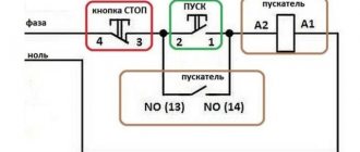
A separate contact group (13H0, 14H0) is designed for the operation of an independent “pickup” circuit. In this mode, the push-button start is activated by pressing once without holding.
Stop button
The control circuit of any starter is organized using two buttons without fixing the on position. “Stop” is indicated in red to enhance safety. In an emergency, this clear identification speeds up the disconnection of the power source.
Starter connection diagram
In the initial position of the “Stop” button, the circuit is closed. When pressed, the induction coil is disconnected from the current source. The electromagnetic field disappears. The spring returns the armature to its original state while simultaneously opening the main contact group. The secondary closure of the circuit in this section does not matter, since the general break is provided by the “Start” button.
For your information. It should be emphasized that modern starters are compact. Such products are suitable for mounting on a standard DIN rail.
Start button
This control element is produced in black (green) color. In the initial state, the contacts are open. Pressing activates the formation of a magnetic field and the movement of the main contact group. “Self-recovery” ensures the functionality of the working power circuit after the start button is returned to its initial position.
Electric starters with thermal relay
As for the thermal relay, as mentioned above, it is used in case of possible long-term overload of equipment or insulation failure. In the circuit of such a relay, a bimetallic plate is installed that opens the circuit when the operating current is exceeded for a long time. The relay failure level is adjustable within ± 15% . Therefore, it is worthwhile to estimate the maximum permissible overload in advance.
However, when using such structures it is not recommended:
- installation in the upper part of the installation cabinet (the hottest air accumulates there);
- use in rooms (or areas thereof) with large temperature differences;
- operation on a chassis subject to strong vibrations or shocks. In particular, installation together with electromagnetic equipment with an operating current of more than 150A is not recommended, since during operation it produces quite strong shocks;
- installation in places where the temperature can rise above 40°.
There are nuances with reversible 220V electromagnetic units. The fact is that they are used mainly for starting , braking and reversing asynchronous electric motors. This operation is performed using a countercurrent supply and is associated with a sharp increase in the load on the main contacts of the starter. In this regard, when choosing a 220V electromagnetic reversing starter, you should include a reserve of one and a half to two times the current.
It may be worth mentioning permanent magnet electromagnetic starters. They are designed to be switched on with direct current and, if used in production, are usually connected via a rectifier.
Classic connection scheme
Magnetic starter PM12
This option is used to solve typical problems. The standard starter connection diagram involves performing certain actions when the control buttons are pressed:
- “Start” – the electromagnet attracts the pad with contact groups, closed circuits supply current to the load;
- “Stop” – the holding of the moving part of the structure by the electromagnetic field stops, the spring returns the block to its original state, and the power to the load is turned off.
If you use a 380V magnetic starter, you can connect a powerful motor or a set of several heating elements. It is permissible to divide the loads into several phases: L1, L2 and L3. In this situation, one should not forget about the uniform distribution of power across individual lines.
Motor connection
In this example, the winding parameters are the same. Therefore, additional calculations of load proportionality are not necessary. Control devices are connected to L1 and the neutral conductor. The voltage in this circuit is 220V (380V between individual phases). For additional protection (not shown in the figure), an automatic circuit breaker is installed at the input, which is selected based on the maximum permissible current.
For your information. You can add a fuse to the circuit in front of the button, which will prevent damage to the coil if the voltage in the power supply network increases significantly.
After briefly pressing the “Start” button, the contact group supplies voltage to the motor windings. The “self-catching” mechanism maintains the working position. The current flow circuit is as follows: L1 – 1 – 2 – self-retaining – 3 – KM – N. To turn off the power unit, press “Stop”, which interrupts the power supply to the load.
To connect an electric motor with a reversible operating mode, use the magnetic starter connection diagram presented below. An added group of controls (Forward and Back buttons) provides power to the windings through different contact groups. The normal direction of rotation or reverse is activated accordingly.
Reverse connection diagram
An additional element, thermal relay RT1, prevents damage to the motor when the rotor is jammed or the drive mechanism is overloaded. Heating the control area opens the power supply circuit to the coils (KM1 or KM2). By analogy with the operation of the “Stop” button, the contact groups are disconnected in the phase lines.
Important! This circuit does not protect against short circuits. The corresponding functions are performed by a machine (QF).
Types of devices
In addition, there are two types of 220V electromagnetic starters:
- conventional - when power is supplied to the electromagnetic starter, the electromagnet attracts a metal core with contacts attached to it. In this case, normally closed contacts open, and normally open contacts close. When the power is turned off, the process is reversed;
- reversible - in essence, they are two conventional electromagnetic starters on the same base and have connections for blocking. This avoids turning on two starters at the same time.
According to the types of equipment connected using an electromagnetic starter, there are three groups: AC-1, AC-3 or AC-4 . They differ in the maximum permissible current of the main circuit and the type of connected load:
- AC-1 – inductive or low-active load;
- AC-3 – direct start mode of electric motors with a squirrel-cage rotor, shutdown of a running engine;
- AC-4 – starting the electric motor with a squirrel-cage rotor, switching off and braking with countercurrent.
Options with a different number of “signal” contacts or the presence of a built-in thermal relay are also possible.
Types of electromagnetic starters
To eliminate errors, you need to clarify the names of products in this group. According to current standards, the starter is a fully functional device with control buttons in a housing protected from dust and moisture. Acceptable presence in the kit:
- thermal relay;
- light indication;
- consoles with additional contact groups.
A contactor, by definition in the standards, consists of a drive and a contact group. To control such a product, an external push-button station is used. Some models do not have a protective housing, as they are intended for indoor use. Remote contactor connection can be automated. Additional external components provide signaling of operating modes and emergency situations.
Control circuit
The figure shows how to connect the contactor to the remote control. This method is used to control remote stationary power units and moving mechanisms (overhead crane drives). Starters for three-phase electric motors are divided into groups to quickly identify the appropriate equipment set.
Selection of operating parameters
| Group | Allowable electric motor power (380V), kW | Rated current depending on version, A | |
| open | closed | ||
| 0 | 1,5 | 3 | 3 |
| 1 | 4 | 10 | 9 |
| 2 | 10 | 25 | 23 |
| 3 | 17 | 40 | 36 |
| 4 | 30 | 63 | 60 |
| 5 | 55 | 110 | 106 |
| 6 | 75 | 150 | 140 |
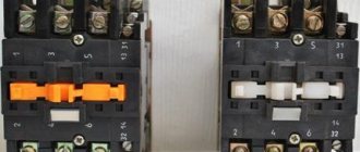
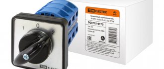
Reversing starter
The picture shows an example of a model with two “Start” buttons (indicated by arrows). Such devices are used to control the direction of rotation of the motor rotor. If necessary, one press activates normal or reverse mode.
Electric starters with thermal relay
These devices prevent damage to connected equipment due to thermal disturbances. In a typical design, a combined plate of two different metals is used. Passing too much current through this element increases the temperature. Since materials differ in linear expansion coefficients, planned deformation occurs. At a certain level, the control circuit (coil) of the magnetic starter breaks. Some thermal relay models have the ability to be adjusted (±25% of the nominal value). The response time ranges from 3 to 25 s.
Contactor connection
Before connecting, it is sometimes useful to make sure the product is working. To make it clear how to check the contactor, it is necessary to find out what algorithm is used to carry out this procedure:
- assessment of condition by visual inspection;
- setting up the magnetic system;
- checking the integrity and insulation resistance of current-carrying elements;
- adjustment of the contact system.
Ease of movement can be checked using a short circuit. If a strong hum is noted, the screws that hold the core and armature are tightened. If frozen metal particles or deposits are found on the contacts, it is necessary to remove them with a file, without using any lubricant.
Before starting the process, it is strongly recommended that you familiarize yourself with the detailed connection diagram.
As a rule, you should first route the incoming cables and secure them with special fasteners. Then the output wires are connected and secured. A thermal relay or a start button may be located in front of the contactor (a rectifier will be required if the button station will use alternating current).
The contact and connection diagram does not depend on the manufacturer and standard sizes of the product. Special marking of contacts allows you to understand the purpose of each of them. You can get a lot of information from the network on how to connect a contactor, but it is not recommended to do such work yourself without having the necessary skills and knowledge.
A large assortment of modular devices designed to work with electrical wiring, as well as other analogues for working with various motor starters, is available on the official website. Photographic materials will help you get an idea of what the contactor looks like, and the characteristics and descriptions will allow you to quickly select the appropriate model.
Modular contactor connection diagram.
Below is a wiring diagram for the modular contactor. The main point of the connection is to supply power to the coil (contacts A1-A2), which will open or close the power contacts NO and NC of the contactor.
Connection to 220 V network
Connecting a magnetic starter to a 220 V network is the simplest, so it makes sense to start familiarizing yourself with these circuits, of which there may be several.
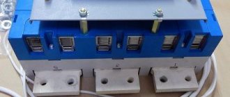
A voltage of 220 V is supplied directly to the coil of the magnetic starter, which are designated as A1 and A2, which are located in the upper part of the housing, as can be seen from the photo.
Connecting a contactor with a 220 V coil
When a regular 220 V plug with a wire is connected to these contacts, the device will start working after the plug is plugged into a 220 V socket.
We recommend reading: How to make a tube headphone amplifier with your own hands
Using power contacts, it is permissible to turn on/off an electrical circuit for any voltage, as long as it does not exceed the permissible parameters indicated in the product passport. For example, you can apply battery voltage (12 V) to the contacts, with which a load with an operating voltage of 12 V will be controlled.
It should be noted that it does not matter which contacts the single-phase control voltage is supplied to, in the form of “zero” and “phase”. In this case, the wires from contacts A1 and A2 can be swapped, which will not affect the operation of the entire device. It is quite natural that such a connection circuit is used extremely rarely, since it requires direct voltage supply to the coil of the magnetic starter
In this case, there are many options for switching on, using a time relay or a twilight sensor, connecting, for example, street lighting to power contacts. The main thing is that the “phase” and “zero” are nearby
It is quite natural that such a switching circuit is used extremely rarely, since it requires direct voltage supply to the coil of the magnetic starter. In this case, there are many options for switching on, using a time relay or a twilight sensor, connecting, for example, street lighting to power contacts. The main thing is that the “phase” and “zero” are nearby.
380 V connection
Connecting a contactor operating with 380 volt networks is almost no different from the previous circuit. The only difference lies in the supply of electricity to the coil. In the original version, this problem was solved by using phase (L3) and zero (N), and in the 3-phase version, the connection is made to two phases L2 and L3.
The completed diagram clearly shows the power supply to the starter coil (KM1), connected to phases L2 and L3. The first is routed through a thermal relay (P), and the second through a push-button element for starting (SB2) and braking (SB1) and an auxiliary contact (KM 1), connected to each other in a series circuit.
The action of this scheme is carried out in a certain sequence. When the starting push-button device is pressed, electricity from one of the phases approaches the coil. Under the influence of a field with magnetic properties, the core is retracted, which causes the entire contact group to short-circuit to the connected load. The current voltage, in this case, is 380 V. The released START button does not interrupt the power supply to the circuit, which is provided by an additional movable contact closed at the moment the core is retracted.
In the event of an emergency, the thermal relay is activated. A phase break occurs, the power is turned off and the coil is de-energized. Under the action of springs, the magnetic core returns to its original position. After opening the contacts, the voltage in the emergency area is removed.
Design versatility
The previous example demonstrates the possibility of using a starter circuit with a start-stop button to solve various problems. If necessary, standard products can be modernized. By adding external components, they provide indication of modes and protective functions, and interface with automation equipment. The basic design is suitable for connecting inductive and resistive loads, operating with direct and alternating currents. When closed, the contact group does not create significant electrical resistance.
Installation of the device
Products in this category are fixed on a flat vertical surface at a stable temperature. The electrical panel uses a standard DIN rail for installation. When choosing a suitable location, excessive vibrations and accidental mechanical damage should be excluded. If the starter circuit is assembled with a thermal relay, the proximity of heating devices is prevented. When installing cable products in clamps, control the position of the washers, avoiding distortions. Stranded copper wires are twisted and tinning is used. Before starting operation, check the free movement of moving components of the structure.
What is a contactor?
In a general sense, this is a remote switch/switch in the electrical network.
Unlike many other switching devices, the contactor has a large safety margin, breaking the electrical network in several places at once, allowing frequent switching on and off of significant loads of powerful electric motors, reactive power compensation systems and other electrical consumers. The operating principle of a contactor is to move an electromechanical coil or relay. When control voltage is applied, the magnetic armature is attracted to the core, closing the power electrical circuit. Since the contactor can have up to 5 groups of contacts, switching occurs in accordance with preliminary settings, or under the guidance of a microprocessor. Each contact can be switched to a normally closed or normally open state.
Modern models have the ability to connect additional external equipment: additional contact attachments, time relays, thermal relays, blocking devices. Thanks to this, the contactor differs from any other switching equipment in its significantly greater versatility and flexibility in setting its operation. For example, a contactor with a thermal relay performs the functions of a magnetic starter, and when setting a delay, it acts as a time relay.
Degree of protection
According to this parameter, single-phase and three-phase models are divided into three main groups according to the international classification of the IP :
- Open version (IP00) does not provide protection from external influences. Installation in special cabinets or rooms with controlled temperatures and limited humidity levels is acceptable.
- Equipment of the IP40 category requires a housing with holes. Use in unheated rooms is permitted, but protection from moisture must be ensured.
- When marked IP54, the product can be installed outdoors. With the help of a canopy, direct exposure to sunlight and precipitation is prevented.
Safety precautions
Regular testing of starters is necessary to maintain safe operation. Basic Rules:
- work with live installations is carried out using special protective equipment;
- disconnected areas are marked and prevent accidental connection of the power source (remove fuses, provide supervision, post warning signs);
- check the absence of voltage;
- use grounding.
The information presented will help you select and use an electromagnetic starter without errors. At the project preparation stage, it is recommended to clarify the intended purpose of the circuit and operating conditions. To solve complex problems, the serial product is supplemented with display means and other external functional components.