A signal is any variable containing some type of information. Moreover, this information can be transmitted over a distance, transferred to storage devices, displayed on the screen and through speakers, or perform similar actions with it. Existing analog and digital are radically different in the nature of their origin, method of transmission and storage.
Analog signal
This natural type of signals surrounds us everywhere and constantly. Sound, image, tactile sensations, smell, taste and brain commands. All signals that arise in the Universe without human participation are analog.
In electronics, electrical engineering and communication systems, analog data transmission has been used since the invention of electricity. A characteristic feature is the continuity and smoothness of parameter changes. Graphically, an analog communication session can be described as a continuous curve corresponding to the magnitude of electrical voltage at a certain point in time. The line changes smoothly, breaks occur only when the connection is broken. In nature and electronics, analog data is generated and distributed continuously. No continuous signal means silence or a black screen.
In continuous communication systems, the analogue of sound, image and any other data is electrical or electromagnetic pulses. For example, the volume and timbre of a voice is transmitted from a microphone to a speaker via an electrical signal. Volume depends on the magnitude, and timbre on the frequency of the voltage. Therefore, during voice communication, first voltage becomes an analogue of sound, and then sound becomes an analogue of voltage. In the same way, any data is transmitted in analog communication systems.
Discrete graphics card
A video card is one of the most important elements of a computer, responsible for visualizing information. The design of the computer can be equipped with either an integrated (built-in) video card or a discrete one . The built-in one is located in the processor or on the motherboard, i.e. it is inseparable from a specific computer.
The discrete video card is made on a separate board, equipped with an individual graphics processor and memory. Therefore, it is more productive than integrated.
Often computers use both types of video cards, which allows the user to switch from one to the other if necessary.
What is a discrete signal
In a digital data storage and transmission system, the absence of a signal is also a form of information exchange. At some point in time it is equal to zero, at another it takes on some value. Therefore, a discontinuous signal is called discrete, hence the name discretus or divided. Analog data is broken down into separate blocks, processed and transmitted as digital code.
Discreteness does not imply a break in communication. Digital systems widely use a binary system for processing and exchanging information. Binary means encoding data using ones and zeros. In a fraction of a second, the signal intermittently takes on the value 1 or 0. Instead of a continuous curve, we have individual discrete values. A certain set of zeros and ones already carries some information. A primitive set is a bit or binary digit. By itself it doesn't mean anything. Data can only be encoded by combining eight bits into the next most complex combination - a byte. The more bytes combined, the more and more accurately the transmitted information can be described.
The quality of the generated data is affected not only by the number of combined bits, but also by the transmission speed. A continuous analog waveform must be broken down into as many more mini discontinuous signal sections. The resulting sound and color will match the original. A high-quality discrete signal forms an exact copy of an analog signal. For example, an MP3 audio track encoded at 320,000 bits per second (320 kbps) is significantly better than one encoded at 128 kbps. Tracks with a speed less than 128 are generally impossible to listen to.
Why is the signal processed?
The signal is processed in order to transmit and receive information that is encrypted in it. Once it is extracted, it can be used in a variety of ways. In some situations it will be reformatted.
There is another reason for processing all the signals. It consists of a slight compression of frequencies (so as not to damage the information). After this, it is formatted and transmitted at slow speeds.
Analog and digital signals use special techniques. In particular, filtering, convolution, correlation. They are necessary to restore the signal if it is damaged or has noise.
What is the difference between a continuous signal and a discrete one?
At first glance, the differences in the signals may not be distinguishable. Both are transmitted as electrical impulses through wires or as electromagnetic waves in the ether. Converted into sound and image, displayed on speakers and screen. But the difference is significant. The difference between an analog signal and a digital signal is due to the peculiarities of data processing and transmission.
Analog data is not encoded or encrypted, it is simply mapped into electrical or electromagnetic pulses. The receiver converts the pulses in full accordance with the received signal. The transmitted and received impulse is multifaceted and is characterized by a constant smooth change over time. Magnitude and frequency determine the parameters of the information. An example would be matching a certain screen color to a given voltage. Over time, the colors change smoothly following the change in voltage.
It would seem that the natural origin, ease of generation, transmission and reception favor the use of an analog signal. But electrical and electromagnetic interference comes into play. This can be electromagnetic interference from electrical networks, operating mechanisms, terrain, thunderstorms, solar storms, noise generated by the operation of transmitting and receiving equipment, and others. They change a smooth curve. The information arrives at the receiver with changes. Hissing, wheezing and distorted images are common in analog communications.
Digital technology uses a completely different transmission principle. Analog data is first encoded and only then transmitted. Coding consists of describing a continuous curve of analog information. At any given moment in time, the transmitted pulse has the value of one or zero, and a certain sequence of bits reflects the entirety of the original picture or sound.
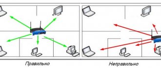
A discrete signal is like Morse code, but instead of dots and dashes there are clear bits. Nothing more, noise and interference do not bother them. The main thing for digital information is to reach the goal. Numbers without impurities will transmit data and be transformed into sound and color without changes. But a weak signal may not convey the full picture. As an example, words or images disappear completely. Therefore, cellular transmitters are installed as close to each other as possible, and repeaters are also used.
An example of continuous and discrete signals would be old wired and new cellular communications. Through old PBXs it was sometimes impossible to talk to the neighboring house. Noise and poor signal amplification made it difficult to hear each other. To have a full-fledged conversation, you had to shout loudly yourself and listen to your interlocutor. Cellular communications based on digital technology are another matter. The sound is encoded and is transmitted well over long distances. You can clearly hear your interlocutor even from another continent.
Both types of communication are not without their drawbacks, and the key differences are:
- Analog is prone to interference and arrives with distortion. While digital comes completely without distortion or is absent at all.
- Any receiver of this principle can receive or intercept analogue broadcasts. A discrete transmission is addressed to a specific recipient, is encrypted and is less accessible to interception.
- The volume of transmitted data in analog communication is finite, so it has practically exhausted its usefulness in transmitting a body signal. On the contrary, with the development of technology for converting analog information into digital code, the volume and quality of broadcasting is growing. For example, the main difference between digital and analog television is the excellent image quality.
Digital technology wins in all respects. The debate is only among music lovers. Many music lovers and sound engineers claim that they can distinguish between an analog original and a digital copy. However, most listeners are unable to do this. And with the development of digital systems, analog data is encoded more accurately. The original sound and the digital copy become almost indistinguishable.
Digital signal
A digital signal is a special data stream; it is described by discrete functions. Its amplitude can take on a certain value from those already specified. If an analog signal is capable of arriving with a huge amount of noise, then a digital signal filters out most of the received noise.
In addition, this type of data transmission transfers information without unnecessary semantic load. Several codes can be sent at once through one physical channel.
There are no types of digital signal, since it stands out as a separate and independent method of data transmission. It represents a binary stream. Nowadays, this signal is considered the most popular. This is due to ease of use.
How an analog signal is converted to digital and vice versa
The first to convert mathematical, physical and computer information into digital form. It was not difficult to describe the formulas and calculations. But to transform analog reality into digital arrays, special devices were already required. They became analog-to-digital converters, or ADCs for short. They are designed to convert various physical quantities into digital codes. The reverse action is performed by DAC devices.
Any digital transmitters and receivers are equipped with such converters. For example, for a cell phone, the incoming sound must be processed and transmitted in digitized form. At the same time, it is necessary to receive a code from the other subscriber, convert it and transmit the voltage to the speaker. The same goes for images on smartphones and TVs. In any case, the initial information is voltage.
There are many types of ADCs, but the most common are the following:
- parallel conversion;
- successive approximation;
- delta-sigma, with charge balancing.
Conversions in ADCs are conceptually related to measurement and comparison. Encoding is the process of comparing data received from a source with a standard. That is, the resulting analog value is compared with the reference value (with a given voltage). The standard is information about a specific color, sound, etc. It corresponds to the ideas about the converted signal embedded in the device. The reference quantity data is then encoded for transmission. During analog-to-digital processing, no physical signal transformations occur. A digital matrix (model) is made from analog.
In a simplified way, the operation of any ADC can be represented as follows:
- Measurement of voltage amplitude at certain time intervals.
- Comparison with the standard and generation of data.
- Uploading digitized information about amplitude changes to the transmitter.
The quality of transmitted information depends on two parameters - accuracy and frequency of measurements. The more accurately the incoming voltage is measured and encrypted, the higher the quality of the transmitted information. Therefore, it matters a lot how many bits the converter can encrypt. The denser the information flow, the more accurate the data transfer. This is expressed in the colors of the screen, the contrast of the picture and the purity of the sound. The next important indicator is sampling, that is, the frequency of measurements. The more often, the less measurement failures and the need for smoothing. Overall, the more frequently and accurately a converter can measure and process the resulting voltage, the better it is.
Types of signals
There are several types of classification of available signals. Let's look at what types there are.
- Based on the physical medium of the data carrier, they are divided into electrical, optical, acoustic and electromagnetic signals. There are several other species, but they are little known.
- According to the method of setting, signals are divided into regular and irregular. The first are deterministic methods of data transmission, which are specified by an analytical function. Random ones are formulated using the theory of probability, and they also take on any values at different periods of time.
- Depending on the functions that describe all signal parameters, data transmission methods can be analog, discrete, digital (a method that is quantized in level). They are used to power many electrical appliances.
Now the reader knows all types of signal transmission. It won’t be difficult for anyone to understand them; the main thing is to think a little and remember the school physics course.
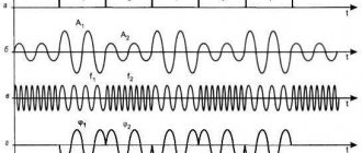
What do the spectra of an analog and discrete signal look like?
The image of signals can be represented as two functions. The figure clearly shows how a continuous signal differs from a discrete signal. The source voltage changes smoothly, while the processed voltage changes intermittently. The discrete spectrum periodically coincides stepwise with the continuous spectrum.
Discrete changes occur abruptly, after a certain period of time. The level in a digital system is encrypted and any voltage value is described in binary code. The smoothness of the transformation and the originality of the transmitted data depend on the frequency of measurements. The more accurately the signal level is described and the more often the measurement is carried out and processed, the more accurately the spectrum of the initial and transmitted signals matches.
Discrete quantity
The discreteness of any quantity implies that its values can be numbered, measured and counted.
Economics, for example, operates with such quantities. Various economic indicators are recorded and calculated at a certain frequency (for example, once a month, quarter, half-year, etc.). Thus, the change in indicators does not occur continuously over time, but as if in “jumps” at set intervals.
Which communication systems use a digital signal and which analog?
Despite its archaic nature, analogue technology is still used for telephone and radio communications. Many wired networks are still analog. These are mainly traditional telephone lines of local operators. But digital channels are already widely used for backbone data transmission. Analogue technology is also used in simple and cheap portable radio stations.
All newly created systems use digital signal processing technology. These are fiber optic and wire lines, signaling and telemetry, military and civil industrial communications. And of course, television is switching to digital broadcasting. The analogue method of data transmission has exhausted itself. It has been replaced by a new high-quality and secure connection.
Application of digital signal
How does a digital electrical signal differ from others? The fact that he is capable of performing complete regeneration in the repeater. When a signal with the slightest interference arrives at communication equipment, it immediately changes its form to digital. This allows, for example, a TV tower to generate a signal again, but without the noise effect.
If the code arrives with large distortions, then, unfortunately, it cannot be restored. If we take analog communications in comparison, then in a similar situation a repeater can extract part of the data, spending a lot of energy.
When discussing cellular communications of different formats, if there is strong distortion on a digital line, it is almost impossible to talk, since words or entire phrases cannot be heard. In this case, analog communication is more effective, because you can continue to conduct a dialogue.
It is precisely because of such problems that repeaters form a digital signal very often in order to reduce the gap in the communication line.
List of books to help you understand analog and digital signals
You can study and compare the principles of data processing and transmission in more detail by reading the following literature:
- Sato Yu. Signal processing. First meeting. / Per. from Japanese; edited by Yoshifumi Amemiya. - M: Publishing House "Dodeka-XXI", 2002. The book provides the basic knowledge about DSP methods. Addressed to radio amateurs, students and schoolchildren just starting to study data transmission systems.
- Introduction to digital filtering / ed. R. Bogner and A. Konstantinidis; translation from English - M: Publishing House "Mir", 1977. This book provides popular and accessible information about various data processing systems. Analogue and digital systems are compared, the pros and cons are described.
- Fundamentals of digital signal processing: Course of lectures /Authors: A.I. Solonina, D.A. Ulakhovich, S.M. Arbuzov, E.B. Soloviev, I.I. Hook. - St. Petersburg: Publishing house "BHV-Petersburg", 2005. The book was written according to a course of lectures for students of the State University of Technology named after. Bonch-Bruevich. The theoretical foundations of data processing are outlined, discrete and digital systems of various conversion methods are described. Intended for study in universities and advanced training of specialists.
- Sergienko A.B. Digital signal processing (second edition) - St. Petersburg: Publishing house "Piter", 2006. Electronic educational and methodological complex for the discipline "Digital signal processing". A course of lectures, a laboratory workshop and methodological recommendations for independent work are presented. Designed for teachers and self-study for undergraduate students.
- Lyons R. Digital signal processing. 2nd ed. Per. from English – M.: Binom-Press LLC, 2006. The book provides detailed information about DSP. Written in clear language and with plenty of illustrations. One of the simplest and most understandable books in Russian.
The good old analogue connection is quickly losing ground. Despite modernization and improvements, the ability to share data has reached its limit. In addition, old diseases remain - distortion and noise. At the same time, digital communications are free of these shortcomings and transmit large amounts of information quickly, efficiently, and without errors.
Signal
A signal is a special code that is transmitted into space by one or more systems. This formulation is general.
In the field of information and communications, a signal is a special data carrier that is used to transmit messages. It can be created, but not accepted; the latter condition is not necessary. If the signal is a message, then “catching” it is considered necessary.
The described code is specified by a mathematical function. It characterizes all possible changes in parameters. In radio engineering theory, this model is considered basic. In it, noise was called an analogue of the signal. It represents a function of time that freely interacts with the transmitted code and distorts it.
The article describes the types of analog and digital. The basic theory on the topic described is also briefly given.
Digital inputs
Discrete (digital) inputs of a programmable logic controller are used to perform a variety of process automation tasks, ranging from monitoring the status of various sensors, such as all kinds of buttons, toggle switches, limit switches, thermostats, etc., to using them to create industrial control panels - PSP- panels, keyboards, emergency switches, as well as when receiving information from actuators - actuators, coils of powerful contactors and relays. In fact, any device with a “relay” or “open collector” output can be connected to a PLC discrete input.
The discrete input of a programmable logic controller can only operate with a low or high signal level. However, some devices and devices have more than two states, corresponding to logical zero and one. To connect such devices, several discrete inputs are used at once. For example, automatic electronic scales that can monitor tolerance thresholds have 2 outputs corresponding to the values “less than normal” and “more than normal”. The weight of the object is thus determined by two bits of information: 01 – “less”, 00 – “normal”, 10 – “more”, 11 – “device malfunction”.
A PLC digital input typically includes a status indicator (LED), galvanic isolation, and misconnection protection. Some controllers have indication diodes located before the galvanic isolation, which allows the user to diagnose the operation of external circuits before turning on the controller. In addition, each discrete input is equipped with an analog filter that suppresses high-frequency interference and upper harmonics of the input signal spectrum. The filter cutoff frequency is matched to the software speed determined by the typical PLC cycle time. The pulse duration, which can be reliably recorded by a general-purpose discrete input, is 2...3 ms. A generalized block diagram of a PLC discrete input is shown in Figure 3.
Rice. 3. Generalized block diagram of a PLC discrete input
Despite the fact that the functionality and operating algorithm of a discrete input are quite simple, its circuit implementation turns out to be not such a trivial task, especially when you consider that modern solutions simultaneously require compact dimensions, reasonable price, high reliability, and minimum consumption values.
Digital outputs
The simplest discrete output of a programmable logic controller is a relay contact and is capable of producing a signal that accepts logical zero or one values. This output is relatively simple to implement and use, but has disadvantages characteristic of relays: limited service life, rather low performance, and so on. A solution that could replace this approach is the use of an electronic power element, which is implemented using a non-contact circuit (transistor for a DC load, triac for an AC load).
According to GOST IEC 61131-2-2012, which we have already addressed earlier, “a digital output is a device that converts a one-bit binary number into a two-state signal.”
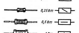
The main characteristics of the digital outputs are:
- rated current load 0.1/0.25/0.5/1/2 A, while the maximum current is 0.12/0.3/0.6/1.2/2.4 A;
- output type – unprotected or short-circuit resistant.
A standard circuit for implementing a discrete output is shown in Figure 16.
Rice. 16. Standard scheme for implementing a discrete output
Current sensors in series with the load continuously monitor the current flowing to the load and report excess current to the controller.
The amount of current flowing in a circuit is one of the key safety parameters. The discrete outputs are designed using NPN transistors with built-in diodes for overvoltage protection. The system ensures that when the PLC digital outputs are turned on, the current from the power supply is always within the controller's specified operating range. The current sensing amplifier can protect digital outputs from overcurrent, provide diagnostics to correct faulty load conditions, and provide system failure warnings.
However, PLC digital outputs can be directly connected to devices that operate with large currents that exceed the permissible current of the PLC output, such as starters, lamps, etc. In this case, it is necessary to use an additional field effect transistor to control the flow of current from the 24 V source to the load. Figure 17 shows the connection of the PLC discrete output to an external low-voltage FET.
Rice. 17. Scheme for implementing a discrete output using an additional field-effect transistor
One of the disadvantages of this approach is the use of an external discrete component (field-effect transistor), which increases the size of the final solution and its cost. An exception to the field-effect transistor from the circuit can be the use of the INA240 current-sensing amplifier, developed by Texas Instruments.
The INA240 is a high-precision bidirectional current amplifier with low input offset and gain drift over a temperature range, making it ideal for measuring currents on discrete digital outputs of PLCs. The INA240 chip is capable of operating with signals up to 400 kHz, has a current consumption of 2.6 mA, a supply voltage of 2.7...5.5 V and is capable of operating at temperatures of -40...125°C. In addition, the INA240 has the industry's best combination of low offset (5 µV), offset drift (50 nV/°C), error and gain drift (0.05% and 0.5 ppm/°C, respectively). This solution also provides AC common mode rejection of 93 dB at 50 kHz.
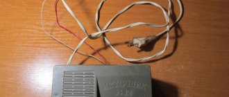
The INA240 is available in 8-pin TSSOP and SO packages, and the TIDA-00909 and TIDA-00913 modules are available to evaluate its capabilities (Figure 18).
Rice. 18. Appearance of the TIDA-00909/00913 module
Brief conclusions
The analog method of data transmission is a relic of the past. But humanity cannot completely abandon this type of signals for one simple reason - all natural information is distributed in this way. And only in this form can a person perceive data.
Scientists have come up with a worthy answer: in the form of a discrete expression of materials. Using special converters, sounds and images are encoded. In this form they are transmitted to the end user, after which they are decoded back into a continuous signal.