Instead of a prologue.
When assembling or repairing audio amplifiers, quite often it is necessary to select pairs of bipolar transistors .
Chinese digital testers can measure the base current transfer coefficient (popularly known as the gain) of a low-power bipolar transistor. Suitable for differential or push-pull input stages. What about a powerful weekend? For these purposes, in the measuring laboratory of a radio amateur engaged in the design or repair of amplifiers, there must be a device for testing transistors . It must measure the gain at high currents close to operating currents.
For reference: the gain of the transistor “scientifically” is called the coefficient of transfer of the base current to the emitter circuit, denoted h21e. Previously it was called “beta” and designated as β, so sometimes old-school radio amateurs the device for testing transistors “betnik”.
On the Internet and amateur radio literature you can find a huge number of options for device circuits for testing transistors . Both quite simple and complex, designed for different modes or automation of the measurement process.
For self-assembly, it was decided to choose a simpler circuit so that our readers could easily make a device for testing transistors with their own hands . Let us note right away that we somehow more often have to deal with amplifiers based on bipolar transistors , therefore the resulting device is designed to measure the parameters of bipolar transistors .
For reference: previously, the editor-in-chief of RadioGazeta carried out measurements in the old-fashioned way: two multimeters (in the base circuit and the emitter circuit) and a “multi-turn” to set the current. Long, but informative - you can not only select transistors, but also remove the dependence of h21e on the collector current. Quite quickly, the realization of the futility of this activity came: for our transistors, removing such a dependence is one frustration (they are so crooked), for imported ones it is a waste of time (all graphs are in the datasheets).
Turning on the soldering iron, the editor-in-chief began to assemble a device for testing transistors with his own hands.
How does it all work?
To test, you need to insert the component to be measured (capacitor, resistor, LED, etc.) into the contacts of the ZIF socket, making sure that the contact numbers are different.
Then hold the component with a special lever and press the button on the device.
The device will turn on and after a couple of seconds it will give you complete information about the inserted component. You will probably say that it is easier to measure with a multimeter. Maybe so, but this only applies to resistors. Measuring other components, for example, capacitors with a multimeter, is long and tedious. In addition, the ESR tester can determine the degree of wear of the capacitor.
The device can be powered from an external power source with a voltage of 9V, or from a Krona battery.
If your feet smell bad, remember where they come from.
After googling a little, I found a diagram of a device for testing transistors , which has been replicated on quite a decent number of sites. Simple, portable... but no one except the author himself praises it. This should have been confusing right away, but alas.
So, the original circuit (with slightly simplified indication and switching):
Click to enlarge
According to the author's idea, here the operational amplifier together with the transistor under test forms a source of stable current. The emitter current in this circuit is constant and is determined by the value of the emitter resistor. Knowing this current, all we have to do is measure the base current, and then by dividing one by the other, obtain the value h21e. (in the author’s version, the scale of the measuring head was immediately calibrated in h21e values).
Two bipolar transistors at the op-amp output serve to increase the load capacity of the microcircuit when measuring high currents. The diode bridge is included in order to eliminate the need to reconnect the ammeter when switching from “pnp” to “npn” transistors. To increase the accuracy of selecting complementary pairs of bipolar transistors, it is necessary to select zener diodes (setting the reference voltage) with the stabilization voltages as close as possible.
I was immediately confused by the “not entirely correct” switching on of the operational amplifier with a single-supply supply. But the breadboard will endure everything, so the circuit was assembled and tested.
Shortcomings immediately emerged. The current through the transistor was highly dependent on the supply voltage, which is not at all reminiscent of a stable current generator . What the author of the circuit managed to select, while powering the device from a battery, remains a big mystery. As the battery discharges, the “exemplary” current will flow away and quite noticeably. Then I had to tinker with the “amplifier” at the op-amp output, otherwise the circuit would work unstably when measuring transistors of different powers. It was necessary to select the value of the resistor, and then I switched to a more “classical” version of the amplifier. And the bipolar (correct) power supply of the op-amp solved the problem with the floating current.
As a result, the diagram took the form:
Click to enlarge
But here another drawback has emerged - if you confuse the conductivity of the bipolar transistor (turn on “pnp” on the device, and connect the “npn” transistor), and when selecting from a large number of transistors, you will definitely forget to switch the device sooner or later, then one will fail from the transistors of the “amplifier” and you will have to repair the device. And why do we need difficulties with bipolar power supply, opamp, amplifier, etc.?
How to test a transistor without desoldering it from the circuit
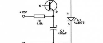
Probe circuit for testing transistors: R1 20 kOhm, C1 20 μF, D2 D7A - Zh.
Desoldering a certain element from a circuit involves some difficulties - it is difficult to determine from its appearance which one needs to be desoldered.
Many professionals suggest using a probe to test the transistor directly in the socket. This device is a blocking generator, in which the role of the active element is played by the part itself that requires testing.
The system of operation of the probe with a complex circuit is based on the inclusion of 2 indicators that indicate whether the circuit is broken or not. Options for their manufacture are widely presented on the Internet.
The sequence of actions when checking transistors with one of these devices is as follows:
- First, a working transistor is tested, with the help of which it is checked whether there is current generation or not. If there is generation, then we continue testing. In the absence of generation, the winding terminals are swapped.
- Next, lamp L1 is checked for open circuit probes. The light should be on. If this does not happen, the terminals of any of the transformer windings are swapped.
- After these procedures, the device begins directly checking the transistor, which is supposedly out of order. Probes are connected to its terminals.
- The switch is set to the PNP or NPN position and the power is turned on.
The glow of lamp L1 indicates the suitability of the circuit element being tested. If lamp L2 starts to light, then there is some problem (most likely the junction between the collector and the emitter is broken);
If none of the lamps lights up, then this is a sign that it is out of order.
There are also probes with very simple circuits that do not require any adjustment before starting work. They are characterized by a very small current that passes through the element to be tested. At the same time, the danger of its failure is practically zero.
This category includes devices consisting of a battery and a light bulb (or LED).
To check, you need to perform the following operations sequentially:
- Connect one of the probes to the most likely output of the base.
- Using the second probe, we touch each of the remaining two terminals in turn. If there is no contact in one of the connections, then an error occurred with the selection of the base. You need to start over with a different order.
- Next, it is advised to perform the same operations with another probe (change positive to negative) on the selected base.
- Alternately connecting the base with probes of different polarities to the collector and emitter should fix the contact in one case, but not in the other. It is believed that such a transistor is working.
Everything ingenious is simple!
I set out to make something simpler and more reliable. I liked the idea with a current source; by carrying out measurements on a fixed (previously known) emitter current, we can reduce the required number of measuring instruments (ammeters). Then I remembered my favorite microcircuit TL431 . The current generator on it is built from only 4 parts: Considering the not very large load capacity of this microcircuit (and it is extremely inconvenient to mount it on a radiator), to test powerful transistors at high currents we will use Mr. Darlington : Now there’s a catch - it’s not in any reference book current source circuits based on TL431 and transistor “pnp” structure. Siklai , no less respected by me, helped solve this problem :
Yes, an inquisitive eye will notice that the currents of both transistors flow through the current-setting resistor here, which introduces some error in the measurements. But, firstly, with values of the base current transfer coefficient of transistor T2 above 20, the error will be less than 5% , which is quite acceptable for amateur radio purposes (we are not launching the Shuttle to Venus).
Secondly, if we do launch the Shuttle and we need high accuracy, this error can easily be taken into account in the calculations. The emitter current of transistor T1 is almost equal to the base current of transistor T2, and this is what we will measure. As a result, when calculating h21e (and this is very convenient to do in Excel), instead of the formula: h21e=Ie/Ib, you need to use the formula: h21e=Ie/Ib-1
To minimize this error, as well as to ensure normal operation of the TL431 microcircuit in a wide range of currents, a transistor with maximum h21e should be selected as transistor T1. Since this is a low-power bipolar transistor, until our device is ready, you can use a Chinese multimeter. I managed to find an instance with a value of 250 out of only 5 KT3102 transistors.
Since today in the household of any radio amateur there is a Chinese multimeter (or even more than one), we will use it as a base current meter, which will allow us not to fence switching for different ranges of base currents (I have a multimeter with automatic limit selection measurements), and at the same time exclude the rectifier bridge from the circuit - the digital multimeter does not care about the direction of the flowing current.
Scheme named after me, Siklai and Darlington.
To combine the above circuits into one, we will add some switching elements, a power supply, and for greater versatility, we will expand the range of emitter currents. The result is the following diagram of a device for testing transistors :
Click to enlarge
With the ratings indicated in the diagram, the calculated emitter current is provided already at +4V supply voltage, so this is truly a stable current generator . For the sake of experimentation, I connected transistors of the wrong structure a couple of times. Nothing burned! Although maybe it was worth asking more current? To be honest, few tests have been carried out on the endurance of this device, time will tell, but I like the beginning.
In principle, the device can be powered even from an unstabilized source, since current stabilization in the circuit is carried out over a very wide range of supply voltages. But! There are transistors (especially domestic ones) in which the base current transfer coefficient strongly depends on the collector-emitter voltage . To eliminate measurement errors due to an unstable network, the circuit provides a stabilized power supply. By the way, it is precisely because of such “curves” of transistors that measurements should be carried out at at least three different current values.
So, the circuit of the device for testing transistors turned out to be very simple, which allows you to easily assemble this device yourself, with your own hands. The device allows you to measure the base current transfer coefficient of low-power and high-power bipolar transistors “pnp” and “npn” structures by measuring the base current at a fixed emitter current.
For low-power bipolar transistors, the selected emitter current values are: 2mA, 5mA, 10mA. For high-power bipolar transistors, measurements are carried out at emitter currents: 50mA, 100mA, 500mA. No one forbids testing medium power transistors at currents of 10mA, 50mA, 100mA. In general, there are a lot of options. The values of the emitter currents can be changed at your discretion by recalculating the corresponding current-setting resistor using the formula:
R= Uо/Iе ,
where Uo is the reference voltage of TL431 (2.5V), Ie is the required emitter current of the transistor under test.
ATTENTION: In nature there are TL431 microcircuits with a reference voltage of 1.2V (I don’t remember how the markings differ). In this case, the values of all current-setting resistors indicated in the diagram must be recalculated!
Examples of measurements of radio components
Using the radio element meter is very simple. You need to install the part and turn on the device. He will test the power, if it is normal, he will begin to check the part installed in the connectors. Based on the test results, a message will be displayed indicating the type of part and its parameters.
Branded device
To make it clearer, let’s look at the work of the popular clones M328 and GM328. The difference between them is the set of possible functions (the GM328 has more). Any device is turned on by briefly pressing the encoder. Pressed, held for 1-2 seconds and released. The device is turned off either by selecting the appropriate line in the main menu (Switch Off) or by holding down the encoder for 10 seconds.
Construction and details.
Due to the simplicity of the device, no printed circuit board was developed; all elements are soldered to the pins of switches and connectors. The entire structure can be assembled in a small case; everything will depend on the dimensions of the transformer and switches used.
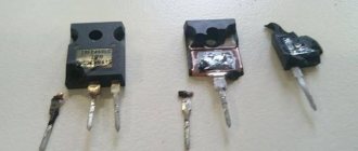
When testing powerful bipolar transistors at high currents (100mA and 500mA), they must be mounted on a radiator ! If a plate radiator is mounted on one of the walls of the device or the radiator itself is used as a wall of the device, this will make using the device more convenient. A radiator that is always with you! This will significantly speed up the process of testing powerful transistors in TO220, TO126, TOP3, TO247 and similar packages.
The power supply stabilizer chip also needs to be installed on a small radiator. Any diode bridge is suitable for a current of 1A and higher. As a transformer, you can use a suitable small-sized one, with a power of 10 W or more with a secondary winding voltage of 10-14 V.
Optional: the device for testing transistors has sockets for connecting a second multimeter (included in the DC voltage measurement mode to a limit of 2-3V). I spotted this idea on one of the forums. This allows you to measure Ube of the transistor (if necessary, calculate the slope). This function is very convenient when selecting bipolar transistors of the same structure for PARALLEL connection in one arm of the amplifier output stage. If at the same current the voltages Ueb differ by no more than 60 mV, then such transistors can be connected in parallel WITHOUT emitter current equalizing resistors. Now do you understand why Accuphase amplifiers, where up to 16 transistors are connected in parallel in each arm in the output stage, cost so much money?
List of elements used:
Resistors: R3 - 820 Ohm, 0.25 W, R4 - 1k2, 0.25 W, R5 - 510 Ohm, 0.25 W, R6 - 260 Ohm, 0.25 W R7 - 5.1 Ohm, 5 W (more is better), R8 - 26 Ohm, 1 W, R9 - 51 Ohm, 0.5 W, R10 - 1k8, 0.25 W.
Capacitors:
C1 - 100nF, 63V, C2 - 1000uF, 35V, C3 - 470uF, 25V
Switching:
S1 - switch type P2K or biscuit for three positions with two groups of contacts for switching, S2 - switch type P2K, toggle switch or biscuit with one group of contacts for switching, S3 - switch type P2K or biscuit for two positions with four groups of contacts for switching, S4 - momentary button, S5 - power switch
Active elements:
T3 - transistor type KT3102 or any low-power npn type with high gain, D3 - TL431, VR1 - integrated stabilizer 7812 (KR142EN8B), LED1 - green LED, BR1 - diode bridge for a current of 1A.
Miscellaneous:
Tr1 is a transformer with a power of 10W or more, with a secondary winding voltage of 10-14V, F1 is a 100mA...250mA fuse, terminals (suitable available) for connecting measuring instruments and the transistor under test.
T7 tester specifications
- Automatic detection of NPN and PNP transistors, n-channel and p-channel MOSFET, diode (including dual diode), thyristor, transistor, resistor, capacitor and other components.
- Automatic component test and LCD display
- Can detect MOSFET protection diode, gain, transistor pin detection
- MOSFET capacitance measurement, threshold voltage
- One button control, automatic shutdown.
- Only 20 nA current when turned off.
- Automatic identification of components based on leg position.
- Bipolar transistor measurements - gain and base-emitter threshold voltage.
- Identifying Darlington transistors.
- Can measure two resistors at the same time, so you can measure a potentiometer.
- Resistance measurement with a resolution of 0.1 ohm, up to 50 megohm can be measured.
- You can measure capacitors of 30pF - 100mf, resolution 1pF.
- Measure equivalent series resistance ESR, resolution 0.01 Ohm.
- Can show forward voltage drop across the diode.
- LED defines as forward voltage drop across the diode
- Can measure the diode's throughput capacitance. If it is a bipolar transistor, it will also show the throughput capacitance.
- Powered by 1000 mAh lithium battery
- Price 25-30$
Working with a transistor tester.
1. Connect a multimeter to the device, turned on in current measurement mode. If there is no “auto” mode, then select the limit in accordance with the type of transistors being tested. For low-power ones - microamps, for high-power bipolar transistors - milliamps. If you are not sure about the choice of mode, set the milliamps first; if the readings are low, switch the device to a lower limit.
2. If there is a need to select transistors with the same Ube, connect a second multimeter to the corresponding sockets of the device in voltage measurement mode to a limit of 2-3V.
3. Connect the device to the network and press the “On” button (S5).
4. With switch S3 we select the structure of the transistor under test “pnp” or “npn”, and with switch S2 its type is low-power or high-power. Using switch S1 we set the minimum value of the emitter current.
5. Connect the leads of the transistor under test to the corresponding sockets. Moreover, if the transistor is powerful, it should be mounted on the radiator.
6. Press the S4 “Measurement” button for 2-3 seconds. We read the multimeter readings and enter them into the table.
7. Using switch S1, set the next value of the emitter current and repeat step 6.
8. Upon completion of measurements, disconnect the transistor from the device, and the device from the network. In principle, paired transistors can be selected based on similar values of the measured base current. If you need to calculate the h21e coefficient or create graphs, you should transfer the data to an Excel spreadsheet or similar.
9. We compare the obtained data in the table and select transistors with similar values.
Calibration
When running the Universal Radio Component Tester for the first time, calibration may be required. If there are instructions, you just need to follow all the steps point by point. Nothing complicated, simple steps, but without them no one can guarantee the accuracy of measurements.
Calibration message
If there are no instructions, you can read the on-screen prompts. Messages are usually in English and are displayed sequentially.
Example of calibration of the GM328 universal tester
Since English is not accessible to everyone, we will give an example of calibration of the Chinese “manufacturer” GM328. This is one of the most popular builds and costs about $12.
To calibrate the GM328 Universal Tester, connect all three measurement pins (areas) using jumpers. It is convenient to make two U-shaped jumpers, the first connects 1-2, the second 2-3. You can make one in the shape of the letter S. The procedure is as follows:
- Turn on your device. Turn on the GM328 by briefly pressing the encoder (some call it encoder).
Go to self-test mode. Because of this:
- As soon as any message lights up on the screen after startup, press the knob again and hold it for 7-8 seconds. Neither more nor less, since at another moment of pressing, a reboot will occur or the device will turn off.
- If you release the handle after 7-8 seconds, the main menu will appear on the screen. It is necessary to switch from the current mode to the self-test mode - “Self-test”. The current mode is highlighted in green or with a check mark (as in the photo). Turn the knob to change position. If you need to go down further, go clockwise
This is the main menu. To calibrate, you need to go to self-test mode - Selftest
- When the desired line is marked, press the knob to confirm your selection.
- After starting the test program, the message Short Probers appears - short test (you will cover all measurement areas with jumpers). It burns for about a minute. During this period, it is necessary to install jumpers.
Requirements for the installation of jumpers and the result of testing the short circuit resistance between measurement zones
- Once the jumpers are inserted, a series of numbers will appear. This is the resistance of the jumpers installed between the contacts.
- After this message is displayed, Probersa Island is displayed. This means that the insulation between the test pins will be further checked and the jumpers must be removed.
When this message appears, the jumpers must be removed
- After removing the jumpers, the following two messages are displayed. They are informational in nature: they show the insulation between the contacts.
This is the measurement area insulation test data
- Then a message appears indicating that it is necessary to install a capacitor with a capacity of more than 100 µF. Its legs need to be inserted into pins 1 and 3. Without this step, the calibration will not be completed. And a message about its necessity will appear before each measurement, which is terribly annoying. Note! The capacitor for calibration must be a sheet capacitor. As a last resort, it is strictly not recommended to use ceramics and electrolytes.
This type of message indicates the need to install a capacitor larger than 100 nF
- Once a capacitor of sufficient capacity is installed, the “Test End” message will appear and the device will continue to operate without annoying messages.
This is an example of calibrating a specific universal radio component tester. This doesn't mean that others will have the same experience. But at least you will have an idea of what may be required of you.
Instead of an epilogue.
A few comments on low-power bipolar transistors (it’s not for nothing that I provided modes for them?). For some reason, radio amateurs, when building amplifiers using transistors, pay the greatest attention (and then in the best case) to the selection of identical specimens for the final stage.
Meanwhile, differential cascades or less often push-pull cascades . At the same time, it is completely forgotten that in order to receive from the differential. cascade, as well as from a push-pull cascade, to maximize all its wonderful properties, the transistors in such a cascade must also be selected !
Moreover, to ensure the closest possible temperature conditions, it is better to glue the housings of the differential cascade transistors together (or press them together with a clamp), rather than spreading them on different sides of the board. The use of integrated transistor assemblies in the input stage eliminates these problems, but such assemblies are sometimes expensive or simply not available to radio amateurs.
Therefore, the selection of low-power transistors for the input stage remains an urgent task, and the proposed device for testing transistors can significantly facilitate this process. Moreover, one of the modes chosen for measurement, a current of 5 mA, is most often the quiescent current of the first stage. And at what current does the Chinese multimeter measure???
Happy creativity!
Editor-in-Chief of RadioGazeta.
Disassembly
Of course I decided to look under the lid. Inside is the same familiar board as in the younger models. I suspect that the difference lies in the firmware and power supply. Well, okay.