What is a welding transformer and what is it used for?
The welding transformer is used to form permanent connections for production and repair purposes so widely that it has already become a classic piece of equipment.
The welding transformer is designed for the following tasks:
- converting high mains voltage into low, and low electric current into high;
- carrying out welding and surfacing works by using coated electrodes.
When combining the results of these processes, manual arc welding is performed. Despite the development of this technology more than 100 years ago, the transformer is still widely used.
The reasons for this are the simplicity and low cost of the device, its low unpretentiousness and high maintainability, as well as its versatility as a technical means of production.
If you want to know what welding methods there are, then follow the link.
Let's consider the design and principle of operation of a welding transformer, as well as its main design features.
The role of the transformer in welding
AC welding transformers are used in manual arc welding using stick electrodes, in mechanized welding using flux, and in argon arc welding for joining parts made of aluminum alloys.
The purpose of the welding transformer is to generate the voltage required for welding, certain constant external characteristics and to regulate the welding current.
The requirements for external parameters are determined based on the following indicators:
- type of electrode - it can be a melting or non-melting rod;
- the nature of the working environment - open arc, submerged arc, in protective gas;
- degree of automation of the welding process - manual, automatic, semi-automatic;
- The method of regulating the combustion mechanism is self-regulation, automatic.
Manual arc welding with coated rods, argon arc welding with a non-consumable tungsten electrode, mechanized submerged arc welding on automatic machines with control of the filler wire feed speed depending on the arc voltage - methods of joining metal parts in which a falling current-voltage characteristic is used.
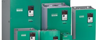
Types of welding transformers.
A falling current-voltage characteristic implies operation of the device in welding current regulator mode. Based on technological and economic considerations, smooth step control is used.
This type of control involves two or more stages of regulation, combined with a smooth change in the current value in each stage.
The rigid current-voltage characteristic is used in automatic submerged arc welding at a constant filler wire feed speed, regardless of arc voltage.
The power supply in this case works as a voltage regulator.
The voltage change can be:
- smooth;
- stepped;
- mixed.
The amount of welding current depends on the speed at which the electrode wire is fed. The power source, in turn, sets the arc voltage and ensures self-regulation of its length.
Depending on the number of phases there are:
- Single-phase welding transformer - a model that operates only at a voltage of 220 V. Designed for domestic needs.
- Three-phase transformer - operates at a network voltage of 380 V. Such models are capable of providing high current output, which makes it possible to connect metal parts of large thickness.
Welding transformer device
A welding transformer consists of the following main parts and assemblies:
primary winding: serves to supply electric current from a power source (household or industrial voltage, generator), is stationary;
secondary winding: in contrast to the primary, which is insulated, the secondary winding is made of wire without insulation, which allows for increased heat transfer to reduce winding resistance, and is made movable;
magnetic core: the mechanical basis on which the windings are installed, and in which a magnetic flux will be formed, therefore it is made of special electrical steels;
fastening screws: they connect not only individual sheets of the magnetic circuit, but also other parts to each other;
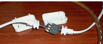
insulated wires: for powering the transformer itself;
terminals or clamps: to remove voltage from the unit and supply it to the product being welded;
metal housing: to accommodate all parts and prevent electrical injuries;
operating current and voltage controls: buttons, switches, etc.
These elements are basic, without them the operation of the unit is impossible.
Other parts are added as needed to expand capabilities. For example, a choke is added to improve current characteristics and smoother control.
To find out how to choose the right cable cross-section for a welding machine, follow the link.
Magnetic circuit design
Any welding transformer is based on a magnetic core; this is its basis. It is designed to conduct the resulting magnetic flux along a closed loop. This principle of operation sets the requirements for it: a single element on which the wire windings are placed.
The classic format of a magnetic circuit is a package of steel plates fastened with screws. Being made from special transformer steel, the plates have increased ferromagnetic properties and become a high-quality conductor of eddy electric currents.
The design of individual plates is advisable for reduced heating of the magnetic circuit. For insulation, they are separated by special varnishes and oxide coatings.
The solidity of the product is ensured by hardware. Tight pinning prevents excessive humming caused by flow shorting on the core. Alternating current changes direction 50 times per second, which leads to vibration of individual plates.
Operating principle of a welding transformer
Welding transformers operate according to the following scheme:
- the primary winding receives electric current from the outside - from a power source connected to the input wires of the device;
- the current flowing through the winding creates an electromotive force (or EMF) in the magnetic circuit - as a phenomenon of directional action, it moves along the existing circuit;
- the EMF flow in the magnetic circuit reaches the secondary winding and generates its own magnetic flux in it, and this in turn generates an electric current;
- The electric current thus obtained is used for welding.
The following is interesting in this process: if you change the total number of turns and the ratio of powered turns on both windings, it becomes possible to obtain the required characteristics of the output voltage and current. It is the quantitative difference between the windings that serves to convert energy to the required parameters.
As a result, the output welding current can be used to melt solid metal. Taking into account the physical and mechanical characteristics of steels and alloys, as well as the parameters of the required connection, welding equipment can be designed within a wide range of energy capabilities.
The design and principle of operation of a welding transformer serve one purpose: to reduce the voltage of the power source (somewhere up to 30 or more volts) and increase the current in the welding arc (300 or more amperes).
If the device is needed to operate on a constant current, it is called a rectifier and is designed a little differently.
Idling
The welding transformer as power equipment is designed for 2 modes of use, which imposes requirements on its operating principle:
- with load - when welding is performed directly;
- idle – when the unit is in standby mode.
The difference between them is the use of the secondary winding. When the welding arc burns, electric current flows through it, but in idle mode it does not. For a welding machine, idle speed is also nominally working.
Despite the apparent absence of current, it is still present: the power input to the primary winding creates an EMF not only using direct magnetic flux - but also by dissipation. If the transformer is not working immediately, a small electric current exists in its magnetic circuit at any time due to dissipation forces.
It is critically important that an “idle” voltage is formed in the secondary winding even without arcing. For a welding transformer, this is a dangerous phenomenon: because of it, the welder can die. For this reason, automatic voltage limiters (usually 48 V) and protective grounding are installed.
Useful article - What is tig argon arc welding
Possible faults
Welding transformers can fail for several reasons. In most cases, repairs can be done yourself. To do this, it is necessary to determine the cause of the failure.
Most often, the welding machine fails when there is a short circuit. It occurs between structural elements. A short circuit causes the device to shut down.
To resume operation of the unit, it is necessary to disassemble it. The faulty element will need to be replaced. Most often, the cause of such a breakdown is the terminal block or the winding passing next to it.
The second reason for device failure is overheating.
It occurs if the voltage value is set higher than that recommended by the manufacturer. If this problem occurs frequently, the rewind will need to be partially or completely replaced. To do this, purchase a wire with the same cross-sectional diameter.
If during operation there is strong noise or buzzing, you will need to disassemble the housing. The cause is a loose nut or bolt. All connections will need to be tightened.
After repairs, the operation of the equipment is tested.
If everything is in order, you can start welding again. The design of the unit is simple and reliable. Therefore, breakdowns and malfunctions in its operation rarely occur.
Welding equipment is widely used by both amateurs and professionals. Using such a device, you can connect thin and thick workpieces, sheets of various materials using an electric arc. Depending on the purpose and conditions of use of the equipment, you should purchase a device with the required technical characteristics.
Of all the different types of industrial equipment, the most common is the welding transformer.
Such a device consists of several key components and is capable of creating a current, the arc of which melts the steel and connects the sides of the product into a single seam. The equipment is divided into several types according to the complexity of the design, as well as the ability to produce the required voltage. What is the principle of operation of a welding transformer and its design?
What physical processes occur inside the device? How can some products differ from others? The article and video will fully cover these issues.
Classification of welding transformers
The welding transformer as technical equipment has several design options, divided mainly according to the principle of operation and purpose. The main classification criteria are:
- supply voltage: 220 or 380 V;
- number of input phases: 1 or 3 phases;
- rated welding current: for a commercially produced transformer it is up to 400 A, for special purposes there are options for 1000 A;
- rated no-load voltage: from 48 to 70 V;
- welding current supply mode: pulsed or continuous;
- sizes and weight: in a wide range - from those carried on the shoulder to powerful models that require a trolley or lifting equipment.
Operating conditions also make their own adjustments. The welding transformer can be stationary or mobile, in a regular or waterproof housing.
Where to order and buy
You can order and buy a welding transformer at any site that specializes in professional construction equipment. When purchasing, you should consider the above criteria. Be sure to read reviews from real users, take into account the price and scope of application.
A welding transformer is a reliable, unpretentious device that can weld any metal thanks to a special current. It was created at the beginning of the last century to work in heavy and light industry. Later it became widespread for work in the construction industry. It has a durable design and works according to a certain principle that is understandable even to a layman.
Welding transformer circuit
To quickly (and most importantly, simply) regulate the current and voltage on the arc, it is important to use simple circuit diagrams for the design of a welding transformer. They can be classified only by technical performance.
The following design options, consisting of a minimum of components, are most often used. This makes the devices quick to repair, and any welder can work on them.
Welding equipment with shunt
Welding with such a unit is simple; its circuit consists of a “regular” base in the form of a magnetic circuit, windings and a metal element inserted into the opening of the magnetic circuit. The latter is massive and is designed to select the generated EMF. This device is used in production.
The principle of operation of the transformer shunt: if it is necessary to reduce the current strength, it is supplied to the magnetic circuit mechanically to the calculated position. The magnetic field also begins to dissipate on it, the total resistance of the electrical circuit changes, which immediately affects the voltage and current.
The whole point is to change the gaps from the edge of the magnetic circuit to the shunt. Due to the decreasing air resistance, part of the magnetic flux passes to the shunt - and does not reach the secondary winding.
Welding transformers with sectional windings
This design includes several windings at once, each of which is a stage for regulation. Each stage has a different number of turns, which, when connected to a circuit, allows it to generate an electric current of varying strength.
The principle of this circuit is to combine the existing stages on the windings to obtain the necessary current-voltage characteristics of the welding arc.
The relative position of the windings is done to reduce bulk. They are wound on top of each other or side by side. To connect, contacts are displayed on a kind of remote control; the required configuration is made using switches.
Full tuning is achieved by the presence of steps in both the secondary and primary windings.
Thyristor welding transformers
The parameters of the welding arc are regulated by the thyristor. The essence of its work is to change the average voltage with alternating current.
Structurally, such a “superstructure” consists of a pair of thyristors, configured symmetrically and mounted towards each other. This ensures strict current-voltage characteristics.
The circuit is characterized by significant efficiency, since when installed on the primary winding, losses from voltage drop will be higher. At the same time, the rated currents in the thyristors themselves are significantly lower.
Components
The design of the welding transformer allows you to lower the voltage and increase the current to carry out the metal melting process.
These indicators are determined when creating and configuring the device. In order for the equipment to perform the established functions, welding transformers include a certain set of components. In addition to the magnetic drive and two windings, the design includes:
- a vertical screw with a ribbon-type thread; a handle for its rotation; a screw running nut; a suspension system (protects from damage); clamps for fastening and exiting wires; a housing with a ventilation grille.
Some welding transformers with variable current may use additional elements to facilitate the work of the master.
Basic malfunctions and methods for their elimination
Welding transformers are technical equipment, so deviations and malfunctions are always possible in them. What course of action to take in the absence of adequate operation of the device should be determined by the situation.
- the transformer turns off by itself: you need to check the wires and their insulation, connections and all parts - the problem most often lies in loss of power or leaky electrical protection (short circuits or voltage breakdowns when it increases during switching on);
- the humming exceeds the usual level: you should tighten the fasteners of the magnetic circuit and coils, check the insulation - the mechanics are very likely to become loose, or check the welding mode down to the type and diameter of the electrode;
- the transformer began to get very hot: re-evaluate its operating mode - most likely, welding is not carried out according to design conditions, at increased current and for too large thicknesses, and also without observing the ratio of time under load and cooling time;
- the contacts overheat: you should clean all connections (after disconnecting the device from the network), assemble them tightly and update the wires if necessary - this leads to deterioration of the connection in the connections;
- the welding current turns out to be higher or lower than the calculated one: check the machine settings regarding the regulatory components, use the stabilizer - they are the ones who create the current;
- the welding current is poorly regulated: the regulating component (choke, windings) should be checked for mechanical damage or voltage breakdown;
- the welding arc goes out and is difficult to re-ignite: checking the entire electrical circuit with special attention to the insulation and condition of the connections - most likely there is a short circuit somewhere;
- after removing the load, the transformer consumes a huge amount of energy: a full check of the windings - a short circuit between individual wires is very likely.
Determination of the malfunction should be done with the voltage removed and after disconnection from the power source. If after checking these options there are still faults, the answer will be given in an electrical workshop.
Main criteria for selection
In order for the device to have high reliability, good maintainability and a durable design, when choosing, it is necessary to pay attention to the current regulation range, on-time, voltage, phase, power consumption, type of cooling and number of posts. It is also important to look at reviews regarding the lack of large dimensions, weight, low arc stability, low PV, strong dependence of seam quality on skill, high energy consumption and the inability to use the device to weld non-ferrous metals and alloys with each other.
You might be interested in this: Checking IGBT transistors
Power is the main criterion when choosing
Note! You need to choose a device taking into account the current strength. Household units operate at 200 A, semi-professional - up to 300 A, and professional - over 300 A. When choosing, you should look at the thickness of the electrodes. The optimal diameter is 2-5 mm for home work.
Advantages and disadvantages of welding transformers
The main “advantages” of a welding transformer are as follows:
- versatility: can be used for a huge number of welding and surfacing options (restoration of parts), but only for ferrous metals;
- relatively economical energy consumption with a well-chosen unit and high-quality efficiency (up to 80-90%);
- high ease of maintenance and maintainability in almost any conditions;
- low cost;
- absence of critical requirements for application conditions.
There are also disadvantages of a transformer welding machine:
- significant dependence on voltage changes in the power source - for this it is optimal to use a stabilizer (built-in or separate), which will lead to leveling of the arc;
- strong splashing of molten metal;
- high dependence of the weld on the qualifications of the welder;
- not used for welding non-ferrous alloys;
- significant weight and dimensions.
Advantages and disadvantages
The positive qualities of transformer equipment include:
- High efficiency, ease of operation and maintenance. Repairing the device does not involve large expenses, which allows it to be used at home.
- Low cost.
The disadvantages include:
- Arc instability. This is due to the AC parameters. To work with such devices, specialized electrodes are used.
- Changes in output voltage, which negatively affect the quality of the weld.
- Inability to use for joining parts made of non-ferrous metals or stainless steel.
- Dimensions and heavy weight, causing difficulties when moving.
We recommend reading: Do-it-yourself reliable plasma cutter. Instructions
How to choose a welding transformer
A welding transformer is not just a ready-made unit; it must be selected for the planned work. This can be done by taking into account the following points:
- place of application and purpose: household (short-term use, current - up to 200 A), professional (can work for a long time, current - up to 300-350 A), industrial (continuous use at currents up to 1000 A);
- power supply voltage: household network with 220 V (plus or minus 10%) or industrial with 380 V;
- customization options: the more there are and the wider the control intervals, the better the result will be;
- power consumption: the greater it is, the better the transformer functions, but you should not forget about the power supply capabilities;
- duration of active work: welding with household models can be carried out for up to 30 minutes, after which the device will have to cool for the same amount of time; for industrial models, welding continues for hours;
- ability to work with a range of electrodes: the transformer is calculated according to the diameter of the rod up to a certain value
- price: saving with the cheapest is not worth it.
Khafizov Ildar
Level IV NAKS specialist
Ask a Question
For installation work, it is better to consider using an inverter, since their size and weight are less, which is important. Also, the use of an inverter ensures high stability of the process, and as a result, a better quality seam.
Varieties
The design and operating principle of an industrial or household welding transformer determine its technical characteristics. There are different principles for classifying equipment. According to their intended purpose, single-post and multi-post devices are distinguished.
In the first case, the device is intended for domestic use. It is installed in inverters with a power of 3-10 kW. The household network is not designed to use a device with a power of more than 10 kW.
Multi-post devices have a complex design. They are used in professional, industrial devices with a power of 10 kW and above. Such a device can serve several workplaces simultaneously.
Based on the phase characteristics, three-phase and single-phase welding transformers are distinguished. There are devices that can switch to different mains voltages. Single-phase units (220 V) are suitable for domestic use, while three-phase equipment (380 V) is required for industrial use.
This sign determines the load at the output. A three-phase device can weld thick parts. Single-phase models cannot do this.
How to make a welding transformer with your own hands
Before physical work, it is important to determine the design and parameters of the product.
Sheets of transformer iron are taken as the basis - if you don’t have this at hand, it is recommended to purchase suitable blanks. The use of ordinary sheet steel will not bring sufficient results. You can take parts of old transformers.
The magnetic core should be made in a closed shape - a square or rectangle, they are more practical than a circle.
To create windings, it is important to select copper wires with high heat resistance. The insulation of this type should be fiberglass or cotton - rubber is not allowed. The cross-section of the wire for the primary winding is about 5-6 square meters. mm, which will allow you to get up to 25 A here.
The cross section for the secondary winding is about 30-35 square meters. mm, a significant welding current will flow here. Insulation must be as reliable as possible.
The windings are made in the same direction. It is necessary to lay additional insulation between the rows - cotton fabric or specially impregnated transformer paper is optimal.
The magnetic core equipped with windings is placed in a steel case. The fasteners are also insulated to prevent current leakage and short circuits. It is important to make the housing with ventilation openings - the transformer gets hot during operation and needs to release heat.
The input and output terminals are fixed in the housing and protected by insulating materials. The switching and control elements should be located on the side plane - not on the top.
For guaranteed quality and to prevent short circuits, it is better to buy factory transformers.