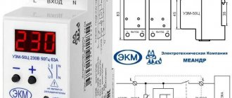
The multifunctional protection device UZM-51m is used to disconnect line consumers at low and high voltage. The standard limits are set to ensure normal operation, from 160 to 280 volts. In addition, the relay protects against pulse surges resulting from lightning strikes, switching on and off powerful installations (motors, starters, magnets). The device is installed on the line in front of the consumer; in the event of an accident, it guarantees a circuit break within a period of 20 milliseconds, which prevents equipment breakdown.
This unit is a voltage controller, which includes an electromagnetic relay and a varistor protective element. The device can be installed on a TN-C, TN-S, TN-CS, TT network.
UZM-51M is a separate element, not intended for line protection; switches operating on automation (RCD, SPD, etc.) are installed along with it.
The distinctive features of the device include:
- possibility of selecting response limits;
- remote control;
- impulse protection is carried out by semiconductors and a varistor;
- setting the time before switching off at low and high voltage.
Return to content
Scope of application
The use of UZM-51 allows you to prevent failure of electrical equipment during sudden power surges in the network. The device is used mainly in everyday life, installed at the entrance of the power cable to an apartment or individual home. The location of the UZM is not accidental - with this method of placement, it becomes possible to completely shut down the house or part of it in the event of an emergency without stabilizing the voltage.
UZM-51 is an indispensable device for protecting devices and electrical equipment from voltage surges
According to GOST, the voltage in the household electrical network should be 220-230 V with a tolerance of ±10%. That is, a voltage of 207-253 V is considered safe for electricity consumers.
If the voltage diverges from the permissible values, installation of protective devices is required, to which UZM-51 belongs.
The causes of voltage drops are:
- phase distortion, that is, the load on one phase is greater than on the second;
- separation or burnout of “zero” with an increase in voltage to 380V;
- short circuit in one of the lines;
- switching on too much power consumers;
- hitting a power line or directly into a consumer with a powerful lightning discharge.
How it works and where to install
In an emergency, the UZM 51MD device detects an arc, analyzes the parameters of the current passing through it and independently breaks the circuit. It does not require any additional contactor or starter to supply the shutdown pulse.
The rated operating switching current is 63A. Which is more than enough for all apartments and private buildings.
All technical characteristics of UZM 51MD (click '+' to view)
It would seem that on the one hand this is good. However, on the other hand, significant problems with the sensitivity of the protection may arise. Either it will be too sensitive, or, on the contrary, it will not respond to small values.
Setting the settings in such a wide current range is not a trivial task. Catching an arc at Imax=1A is not quite the same as at I=63A.
Why do you think foreign analogues are usually produced with ratings up to 20-25A and less. They have clearly already encountered these problems and have developed a more competent approach.
For example, you don’t install an RCD with a leakage current of 10-30mA at the main input. Otherwise, due to the summation of all interference and “left” interference, there will be constant false shutdowns. It has already become the norm for everyone that such RCDs are installed on separate lines or groups.
Another note about installation on the main input of the distribution board is our winter conditions. Think about what will happen to the boiler room in winter at minus 30 degrees, if in your absence this device catches a glitch and falsely turns off all power supply.
Therefore, the more correct approach here would be the same as with UZOshki. It is wiser to place them on separate groups of lines, rather than on the entire house.
In the West, many TB specialists generally prohibit the installation of such devices on inputs. (link to original)
And if the total load exceeds 63A, can such a protection device be connected via a contactor to increase the switching capacity of the relay? No you can not.
The load current must always pass through the AFDD only. If you put it on the starter coil, then this device will not bring you any benefit.
Operating principle
The regulators located on the device body are controlled with a screwdriver. The upper regulator allows you to set the voltage in the range from 240 to 290 V, the lower – from 100 to 210 V. When measuring voltage, an error of up to 3% is allowed.
Tip #1: Before connecting the device, you should test it.
During testing, there is a delay of 5 seconds and subsequent activation of the green indicator with the inclusion of an internal relay. If the voltage meets the standards, two lights light up - green and yellow. Quick start is activated by pressing the test button.
After a voltage drop and its return to normal within a certain interval, the relay turns on after 10 seconds. It is possible to configure the relay response after a drop. The setting is made in the range from 10 seconds to 6 minutes, other values are not provided.
To configure:
- turn off the device by pressing the test button;
- Press and hold the button again until the green indicator blinks repeatedly - the response time of the device will be set to 10 seconds;
- When the red light comes on, the time is 6 minutes;
- Release the button and press it again to restart the device.
It should be understood that pressing the button that switches the device to test mode affects the trouble-free operation of the UZM in the event of an emergency. When the voltage approaches the highest value, the red indicator begins to blink. Exceeding the permissible threshold leads to the deactivation of the yellow light and the red light comes on.
When the voltage drops below the set value, the green indicator starts blinking first, then the timer is activated until the red indicator turns off and blinks. Then the red light comes on with a two-second delay, and the yellow light turns off. After the voltage stabilizes, a timer is activated, showing how many minutes and seconds remain before connection. At the same time, the green indicator continues to blink. If the network parameters do not correspond to the set ones, the time is reset to zero and a new countdown begins. After the delay time has expired, the UZM is turned on.
When the red and green lights blink alternately, it is necessary to turn off the relay using the test button. When you press it again and hold it for two seconds, the relay starts working in normal mode.
Turning on the UZM-51 breaks the power cable, the “zero” is set through and cannot be switched. One-sided zero connection is also allowed, so that zero phases can be connected from below three-phase lines.
Operating principle of UZM-51M
The UZM includes an internal relay and a protection system. On the top of the device there are terminals for the phase and neutral wires. The outgoing terminals U and N are located at the bottom. The device is designed for cables with a cross-section of up to 35 sq. mm. There are two indicators on the front panel that indicate the functionality of the power line. When the green light is on, it means the network is operational. If the red light comes on, it means that there is a fault in the network.
The second indicator should glow yellow, indicating the operating position of the device. The main element of the UZM is a microscopic controller with six terminals. All relay elements can operate for a long time at a voltage of 440 volts.
Before operation, this device must be tested. In this case, press the Test button, then there is a five-second delay, then the green light comes on. After this, the internal relay is turned on.
Next activation
The built-in relay starts to turn on ten seconds after the device returns to normal due to a power surge. In this case, you can independently set this time parameter to 10 seconds or 6 minutes. To do this, you need to: press the Test button, then press it again while holding it until the green indicator starts flashing.
This indicates that a ten-minute time delay has been set to turn the device back on. If the consumer wants to replace this indicator with a six-minute delay, you need to wait until the red indicator lights up.
At the end of these manipulations, turn off the button and press it again to activate the device. This pressing facilitates triggering in the event of an emergency. If the voltage indicator deviates from the normalized value and approaches the maximum value, the red light comes on and begins to blink. At the same time, the yellow light on the device goes out and the red indicator starts to light.
If the voltage indicator begins to decrease significantly, the yellow light begins to blink, after which the response time countdown starts and the red indicator lights up. Moreover, the orange light goes out. When the voltage returns to normal, the device stabilizes, during which the green light flashes. After the delay time has expired, the device turns on and operates as before.
If the device flashes red and green alternately, this indicates that the device has been forced to turn off using the testing button. In this case, you need to press it again and hold it in this state for two seconds, the device will work again, and the yellow light will light up.
Main characteristics
The dimensions of the device are 83x35x63 mm. Thanks to the thoughtfulness and ergonomic design of the UZM, it is very easy to connect.
The main technical characteristics of the device are as follows:
- duration of service - 10 years;
- pause before deactivation - 20 ms;
- absorbing energy -200 J;
- current strength during short circuit - 4.5 kA;
- mains current - 80 A;
- Energy consumption - 1.5 W per hour;
- weight - 160 g;
- degree of protection: housing - IP40, terminals - IP0;
- impulse immunity to interference - level 3.
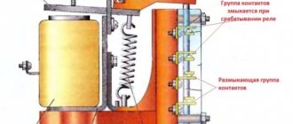
Design Features
The UZM is equipped with a varistor protection system with a relay located inside. The device body, made of plastic, contains input contacts L and N at the top, N and U at the bottom. Their design is tunnel, guaranteeing reliable clamping of wires with an area of up to 35 mm2.
There are two indicators on the front panel. The first one shows the current operating mode:
- green indicates normal operation of the device;
- red indicates a fault.
The second light bulb is yellow. It indicates the operation of the relay.
There is also a test mode button on the front that controls the device manually. The UZM housing contains regulators for operating voltage range limits.
The design of the UZM-51 is quite simple and ergonomic, intuitive even for a non-specialist
The control part is a microscopic controller PIC12F683, which has 6 pins and operates in online mode. Each element of the device can operate for a long time under voltage of 440V. The board contains many SMD parts.
Voltage relay UZM-51M
The device does not have a digital display. The adjustment is carried out by two switches in increments of 5V for the upper threshold and 10V for the lower. There are LED indicators that show the relay status. If the green light starts blinking, it means the voltage in the network is below normal; if it’s red, the voltage is overvoltage.
The response time depends on the network voltage. From 0.02 sec (U=300V and more) and 0.2 sec (U more than 230V). Previously, there were many complaints about the quality of the capacitors in the UZM-51M. Within two years they dried out and the relay began to “glitch”. According to the manufacturers, the problem has now been resolved.
More features:
- simple connection (two inputs – phase + zero)
- rated current – up to 63A
- The width of the DIN rail occupies 2 modules (35mm)
- Recommended operating temperature is from -20 to +55 degrees. It is not suitable for installation on the street, but it is quite suitable in the entrance of a house.
There are other types of UZM relays, namely UZM-16 and UZM-50M. A separate electrical receiver is connected to UZM-16, since this relay is designed for a current of 16A.
They are already set at the factory - 265V upper and 170V lower. There are also three-phase UMZ-3-63. They are mainly used in circuits with electric motor loads.
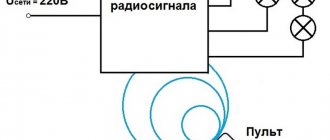
Connection diagrams
The diagrams by which UZM-51 is connected are shown in Figures 1-3.
Connection diagrams for UZM-51 depending on the number of wires and the presence of remote control
- When connecting four wires, the input conductor is placed at the top, and the output for electrical appliances is at the bottom.
- If three wires are connected, then the phase is passed through the UZM, “zero” is required to power the device itself.
- When connecting the remote control, “zero” passes through the switch, the device itself is switched through the power cable, and the load and voltage are supplied.
Connection diagram of the UZM-51 device to a three-phase network indicating the main dimensions
Example video showing the operation of a voltage relay
Special devices - voltage control relays - help solve the problem of voltage surges in networks. The principle of operation of such relays is quite simple, there is an “electronic unit” that monitors that the voltage is within the limits specified by the settings and if there are deviations, it signals the release (power section), which turns off the network. All household voltage control relays turn on automatically after a certain time. For ordinary consumers, a delay of a few seconds is sufficient, but for refrigerators and air conditioners with compressors a delay of several minutes is needed.
Voltage control relays are available in single-phase and three-phase types. Single-phase voltage relays disconnect one phase, while three-phase voltage relays disconnect all three phases at the same time. When using a three-phase connection at home, single-phase voltage relays should be used so that voltage fluctuations on one phase do not lead to the shutdown of other phases. Three-phase ones are used to protect motors and other three-phase consumers.
I divide surge protection devices into three types: UZM-51M from Meander, Zubr from Electronics and all the others. I am not imposing anything on anyone - this is my personal opinion.
Voltage relay Zubr (Rbuz)
This device is designed to protect against voltage surges (zero burnout). BISON is produced in Donetsk.
I will note the features of this voltage relay.
Voltage indication on the device – shows the voltage value in real time. This is quite convenient and necessary for assessing the voltage situation in the network. The reading error is low, the difference relative to the Fluke 87 high-precision multimeter is only 1-2 Volts.
Zubr voltage relays are produced for various rated currents: 25, 32, 40, 50 and 63A. The device, with a rated current of 63A, can withstand a current of 80A for 10 minutes.
The upper voltage value is set from 220 to 280 V in steps of 1 Volt, the lower - from 120 to 210 V. The restart time is from 3 to 600 seconds, in steps of 3 seconds.
I set the Zubr relay, the maximum (upper) voltage value is 250 Volts, and the lower value is 190 Volts.
Devices with the index t in the name, for example Zubr D63t, have thermal protection against internal overheating. Those. when the temperature of the device itself increases to 80 degrees (for example, due to heating of the contacts), it turns off.
Zubr relays occupy 3 modules or 53 mm on a DIN rail and are only single-phase.
The passport and the Zubr connection diagrams provided do not say about current limitations, but in the old documentation it was previously indicated that no more than 0.75 of the nominal.
Two-phase network
Connecting the device to a two-phase network is carried out using several methods.
It is recommended to use a converter with a single adapter. A beam transceiver is selected for connection. Filters are mounted behind the trigger. To stabilize the voltage, a dinistor with a low voltage is needed. The output voltage in the circuit should be no more than 230 V.
Tip #2: Immediately before making the connection, you need to check the resistance, which should not be more than 35 Ohms. In case of sudden voltage drops, broadband dinistors should be installed. With a double converter circuit, the installation of a controller is additionally required.
UZIS S1-40
First of all, pay attention to the connection diagram. Here the 220V supply voltage must be supplied to the lower terminals, otherwise the device will not work normally
But for example, in similar “automatic machines” AFDD from ABB ARC1, the connection is freely made both from above and from below
What do the inscriptions on the body indicate?
But for example, in similar “automatic machines” AFDD from ABB ARC1, the connection is freely made both from above and from below. As evidenced by the inscriptions on the case.
Here are 3 diagrams for connecting an AFSD depending on the switching device at the input:
Some are concerned about the question - what will happen if you confuse the connection of phase and zero, because it is not for nothing that the device is marked L and N.
In most cases, the work will be normal, without any comments. But if a parallel phase breakdown occurs on a grounded part of the equipment, an unforeseen situation may arise.
The current that should go through a special sensor will not go through it. His path will run through neutral. As a result, the parameters of the throws will be completely unpredictable for the UZIS, both in shape and in magnitude.
So it is better not to confuse zero with phase when connecting.
Single-phase network
The UZM is connected to a single-phase network via wired contacts. With this connection, a 200 V thyristor can be used, the filters are placed behind the plate, and the rectifier is mounted last.
For voltage stability, pulse or operational type contactors are used. The problem with magnetic oscillations is eliminated by using pass-through filters. In VO shields, filters are used with a grid winding, the converter is installed with three contacts. In this case, the maximum resistance should be less than 30 Ohms, the average output voltage should be 230 V.
Connection diagram of the UZM-51 device to a single-phase circuit in a private house or apartment
Review of manufacturers
| Manufacturer | Peculiarities | Approximate price, rub. |
| Meander | UHL4, load 63A, 2 modules | 2530 |
| LLC "Relay and Automation" | Mains voltage range 160-280 V | 2000 |
| LLC "Avtomatika-plus" | UHL4, load 63A, 2 modules | 2540 |
| Electroclub Novokuybyshevsk | Mains voltage range 209-233 V | 2800 |
Analogs
Analogues of the UZM-51 device include the following devices:
- OM-63 from ;
- RN-106 from NovaTek.
RN-106 is a voltage relay that protects against unauthorized entry into an apartment with a voltage of 380 V. Too high a voltage leads to the failure of all household appliances connected to the network at that moment.
Voltage relay RN-106 prevents failure of home appliances
The OM-63 power limiter is used primarily in single-phase networks. The device immediately turns off the power supply to the home when the power consumption exceeds the established threshold. The device also protects electrical equipment connected to the network from the negative effects of significant voltage drops from nearby lightning strikes or the inclusion of overly powerful equipment.
Connection errors
- A common mistake is incorrect calculation of the load from electricity consumers, performed independently without the proper experience and knowledge. Before installing UZM-51, it is necessary to correctly perform all calculations, which are best left to professionals.
- Also, neutral is often passed through the UZM, which is not necessary at all. It can simply be connected to any contact.
The UZM-51 connection diagram via a varistor can be called effective, but not reliable. During a thunderstorm, the varistor burns out first. Therefore, it is better to choose a circuit without a varistor.
- SPD - surge voltage protection, classes, connection diagrams
- Indicating relay (field of application, types, connection)
Switching off short-circuit currents
Another design criticism that worries many experienced electricians is the complete lack of any resemblance to arc chutes.
On the same UZM-51MD it is indicated that its maximum breaking capacity is 4.5 kA.
But here there is nothing. How will this affect the contacts during operation during switching shutdowns and switching ons? Not under normal conditions.
This can be explained primarily by the fact that the ultrasonic protection system should functionally only work in tandem with a circuit breaker or a differential switch, which is responsible for the entire function of short-circuit protection and disconnection of emergency current loads.
At short-circuit currents up to 6 kA, the contacts of the ultrasonic device will be closed and its main task is to “endure” and pass this current through itself without consequences, which it successfully copes with. It is precisely the circuit breaker that should break an arc of such magnitude.