Today, manufacturers supply many different electrical products to the construction market. Let's look at what the junction box is used for. Let's get acquainted with the criteria for selecting products depending on the purpose and operating conditions. Read to the end and you will find out what must be taken into account for the proper installation of electrical communications inside or outside the building, in dry, dusty or damp rooms.
Variety of electrical junction boxes Source sellpax.com
General description of products
Engineering communications are a network of a central channel, branches, and end points. For the system to function properly, it is necessary to form reliable nodal connections of individual elements. In the case of electrical wiring, the event is carried out using electrical junction boxes.
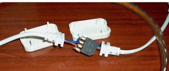
In fact, the device is represented by a box with a lid. Install it at each node branch. The main goal here is to isolate contact connections from possible environmental influences and unauthorized mechanical influence. It also protects the premises from fires during a short circuit and protects people from electric shock. Additionally, two problems are solved: access to contact nodes for various purposes, and a decorative component.
Dimensions and installation location
A standard box for household needs is 10 centimeters in diameter. Design features and dimensions depend on the number of inputs and the number of consumers. The greater the electrical demand, the larger the distributor.
Overhead devices are usually mounted 15–30 cm below the ceiling. This is a special maneuver by electricians to minimize access and eliminate an accident. If the apartment has a suspended ceiling, the box is skillfully disguised as a rubberized sheet. This is an erroneous action during installation, since access to the point should always be unobstructed.
In order to hide the wiring, distribution. the box is installed in a specially drilled hole in the wall of the specified diameter. The height of the point is determined similarly to overhead boxes.
Internal classification
Distribution boxes are used for electrical wiring at any facility that is served by the power grid. Communications are represented by cables with different characteristics and wires that are pulled through the building in various ways.
Cable products for power supply of buildings Source newstes.ru
Therefore, each specific branch has its own standards and requirements. They also apply to electrical distribution boxes.
Installation method
The power grid is stretched inside and outside the building in two ways: on top and inside architectural structures. For the first case, overhead boxes are used. They can be attached to the base using the back wall. Either the fasteners are located inside the product, or outside using mounting lugs with holes for self-tapping screws.
There are two types of boxes for hidden electrical wiring. Some sink into a pre-formed seat in a monolithic base. The body is fixed using a quick-hardening plaster mortar. The second option is intended for structures made of sheet cladding materials. Here, along the outer walls of the box, there are tabs with screws for attaching the body to the canvas.
By material
Internal and external distribution boxes are made of metal or plastic. For the production of the former, tin-plated sheet steel or blanks from aluminum-based alloys are used.
Metal junction box Source el-deco.ru
The prototypes of such products are considered to be cans, in which neat holes were formed using a drill. But unlike them, modern samples meet various technical requirements, including inertness to corrosion.
The advantages of metal products include:
- resistance to various types of mechanical stress;
- long-term resistance to open flame, freezing without deformation of the body;
- durability (depends on inertness to corrosion processes).
Hard plastic is used so that the box retains its shape after mechanical load. It can be polyamide, polypropylene, fluoroplastic. The material is superior to metal in light weight, corrosion resistance, and cost. Another advantage is its high resistance to electric current, that is, the polymer is considered a good insulator.
Plastic electrical distribution boxes Source gorazd25.ru
See also: Catalog of companies that specialize in electrical work of any complexity
Physical parameters
The distribution box for electrical wiring is manufactured with a round, square or rectangular cross-section. The former are more often used for installation in monolithic structures. This is justified by the technique of forming the seat - using a diamond crown by drilling. Here it is convenient to hide the contact connections of a small number of wires, which is important for diverting a switch or socket from the main cable.
Square and rectangular boxes are used more often for outdoor installation. It is easier to distribute several contact connections in them. Therefore, more branches are formed here than in round analogues.
The table shows the standard sizes of distribution boxes for electrical wiring made of polypropylene.
| Section (in mm) | Depth (in mm) |
| Round | |
| 70 | 50 |
| 80 | 50 |
| Round IP55 | |
| 65 | 40 |
| Square IP54 | |
| 85*85 | 35 |
| Square IP55 | |
| 70*70 | 40 |
| 80*80 | 40 |
| 100*100 | 50 |
| Rectangular IP54 | |
| 80*43 | 35 |
| Rectangular IP55 | |
| 120*80 | 50 |
| 150*110 | 70 |
| 190*140 | 70 |
| 200*140 | 75 |
| 240*190 | 90 |
| 240*195 | 90 |
| 300*220 | 90 |
| 380*300 | 120 |
In the residential sector, three options for square boxes are considered the most popular. These are IP54 100*100*50 mm, IP55 80*80*40 mm, IP65 88*88*53 mm. The round ones presented in the table are all used.
Basic wire branching diagrams
Methods of connecting wires are one thing, but knowing where and which conductor to connect is something completely different.
Connecting sockets
As a rule, especially recently, the socket group of wires, as well as the lighting group of wires, are separated and function independently of each other. Despite this, these lines can be located in the same distribution box if the number of connection points is minimal. Otherwise, the outlet and lighting lines may have their own distribution boxes, which are connected by separate wires to the distribution panel. Wiring is carried out using multi-colored wires. The brown wire is considered the phase wire, the cyan (blue) wire is considered the neutral wire, and the yellow-green wire connects to ground, although there may be other wire colors.
Wiring diagram for a socket in a distribution box
Wires of the same color are always connected into separate groups to make it easier to find faults and make adjustments.
The wires are inserted into a junction box, cut to a certain length, after which they are stripped of insulation and connected in the required manner.
Wiring is possible with both three-core and two-wire wires, without a grounding conductor (yellow-green). In addition, “noodles” or cable products with single-color (usually white) wires are often used. In this case, you will have to arm yourself with a device with which the conductors are called, otherwise you can get confused by connecting the phase wire with the neutral wire, which will lead to a short circuit. After testing, each wire is marked, for example, with a piece of electrical tape. If there are two wires, then the phase wire is marked, but there is no point in marking the neutral wire.
Connecting a single-key switch
If the sockets are connected in parallel, the phase conductor is to the phase conductor, and the neutral conductor is to the neutral conductor (if there is a grounding conductor, then they are also connected to each other). If there is a switch in the circuit, then it is a little more complicated, although this complexity is quite conditional. The only thing is that the junction box will have three wires:
- Network connection wire.
- Connection wire from the lighting fixture.
- Wire from the switch.
Since the purpose of the switch is to switch the light source, it is connected to the phase conductor break. In the image below you can see how the switch is connected.
Connecting a single-key switch in a distribution box
If you look closely, it turns out that one (phase) wire is connected to the switch, after which the wire from the switch is connected to the lighting fixture, and the lighting fixture is then connected to the neutral wire. If there is a grounding conductor, then they are connected directly to each other in the junction box.
Single-key switch connection diagram
Connecting a two-gang switch
Two-key switches are used when it is necessary to divide the lighting into two groups. In this case, the lighting device is connected to the line using a three-core cable. One of the wires is connected directly to the neutral wire, and the other two to the two-key switch (to its independent contacts).
Connection diagram for two-button switch
As for the two-key switch, it has two dependent contacts (two common contacts) that must be connected to the phase wire.
Wire connection diagram for a two-key switch
This video demonstrates how to wire a two-gang switch.
Connection diagram for two-button switch
Video description
In the video, a specialist explains how to correctly design the location of distribution boxes:
Work begins with the formation of grooves (if hidden wiring is planned), distribution of wires and points of electricity consumption. To prevent confusion in the future, each conductor is marked. For example, introductory, for light, for sconces, for a kitchen or an outlet.
The connection rules look like this:
- the cross-section of the cores is observed depending on the purpose of the specific cable (from the panel - 4 sq. mm, for the lighting network - 2.5 sq. mm, for unloaded sockets 1.5 sq. mm is enough);
- connections are made in series based on a specific type of conductor (neutral, phase or ground);
- The contact between copper and aluminum is formed using special connectors.
After inserting the necessary wires into the holes, the box is fixed. Inside, the ends should be 5-7 cm long. The veins are exposed by about 10 mm. Connections are formed in accordance with the diagram using terminals, clamps, twists, and soldering.
An example of the formation of contact connections and their distribution in a box Source rusenergetics.ru
Everything is neatly distributed throughout the interior of the box. Installation ends with fixing the cover or frame from the socket or switch.
Connecting the branch box
The wiring diagram is determined by the installation diagram, which is developed before the start of work. A neutral, phase wire and grounding must be installed in each box. The devices are connected to wires that go to switches and sockets.
Since the box allows you to connect different groups of wires, keep in mind that they must belong to the same network, type of voltage and the same type of current. Radio, telephone and fiber optic lines cannot be connected together in one design.
When one of the lines in a mixed distribution box is disconnected, at least one active circuit will certainly remain under current voltage, which is very dangerous. Therefore, if you plan to install different lines, you must provide a separate distribution box for each of them.
When introducing cables into the box, their outer shell is cut so that at least a small part of it goes inside - 0.5-1 cm. To prevent the cable from slipping out, it is carefully secured at the input and output, as well as along the entire route every cm. The length of the gaps depends on its rigidity.
Briefly about the main thing
Distribution boxes are used to hide contact connections of conductors from contamination, moisture, and physical impact. Open access to nodes is also provided.
The boxes differ in design, installation method, application, material and permissible operating conditions.
Additionally, products can be equipped with rubber seals, covers, terminals and clamps, and fasteners.
According to the degree of protection, open boxes (socket boxes) are distinguished that protect contacts from dust, moisture or fire, and are permissible for immersion in the ground or in a body of water.
Arrangement of junction boxes
The junction box, also known as the distribution box, is the location and protection of the connections of electrical wires and cables.
After installing the socket in the electrical box, it is necessary to connect the power supply to it. Since running a separate cable from the distribution panel to each consumer is impractical, switching is performed from the main wire connected to the junction box. It is in it that electrical wires going to various consumers are connected. This method is aesthetically neat and safe.
Junction boxes should be installed in easily accessible places for ease of service. Access to wires must be quick and unhindered. The number of junction boxes in one room is not regulated, but aesthetic characteristics and expediency must be taken into account. The location is usually under the ceiling. In wet rooms - showers, bathrooms - junction boxes are placed on the outer wall, and not inside.
Junction boxes can be either external or internal. And, just like the socket boxes, they fit under brick/plasterboard.
