2.3.3.1 Resistance measurement using the four-wire method (4P)
Use the “Mode” button to select the four-wire measurement method.
Measuring using the four-wire method excludes from the measurement result the resistance of the measuring cables and the transition resistances at their connection points, which is important when the measured resistance is small. Connect the cables to the measuring sockets T1, P1, P2, T2. Connect to the measured resistance (R) on one side the cables from sockets T1 and P1, and on the other side the cables from sockets P2 and T2 in accordance with Figure 2.3.3.1. Briefly press the “Rx / ¿
».
How to use
First of all, it is necessary to determine the location of the pins. It is clear that this location determines the location of the grounding structure. The pins (electrodes) are installed along one line. The distance between them is determined by the depth of immersion, or, more precisely, five times greater than this depth. In this case, the electrodes themselves must be clean.
So, the pins are installed, you can connect the IS 10 meter to the electrodes. On the device itself there are special sockets for this, which are numbered: T1, T2, P1 and P2. It is necessary to connect the electrodes to the device in a certain sequence, as shown in the figure below:
Please note that the cables (wires) are connected to the electrode pins using “crocodiles”. Now you need to configure IC 10 (ground resistance meter)
This device can take measurements in two modes:
Now you need to configure IC 10 (ground resistance meter). This device can take measurements in two modes:
- 4P is the so-called four-wire method;
- Rud. – this is a measurement of the so-called automatic calculation of soil resistance, meaning its specific value.
First way
To use this method, you need to turn on the meter, enter the “Modes” section, where you select the “4P” method. Then the “Rx” button is pressed. The display will show the ground resistance reading. To find out the specific value of this indicator (true), you must use the following formula:
Ru=2πDRe, where D is the distance between the electrodes, Re is the readings of the device itself.
2.3.3.2 Resistance measurement using the two-wire method (2P)
Use the “Mode” button to select a two-wire measurement method; connect the measuring cables only to sockets T1 and T2. Briefly press the “Rx / ¿
", read the measurement result, consisting of the resistance of the measured object and the resistance of the measuring cables and transition resistances at their connection points. The influence of cable resistance can be eliminated by measuring the resistance of the test cables shorted together, which is then subtracted from the main measurement.
The device allows you to correct the zero of the device - write the resistance of the measuring cables into memory and automatically subtract it from the measurement result. To do this, short-circuit the ends of the measuring cables, enter the “MENU”, select the “CALIBER” function. >0<" and press the "Rx / ¿
" The device will measure the cable resistance and record the result in memory. The measurement result and the inscription “READY” will appear on the indicator. The zero correction operating mode will turn on automatically. In this case, the symbol “>0<” appears on the indicator. When replacing measuring cables, it is necessary to carry out a zero correction again so as not to obtain an incorrect measurement result. To turn off zero correction, enter the “MENU”, select the function “>0< OFF” and press the “Rx /
¿
».
2.3.4 Measuring ground resistance using the four-wire method (4P)
If the controlled object uses its own rules (methods) for measuring grounding resistance, then it is necessary to be guided by them.
Use the “Mode” button to select the four-wire measurement method.
Determine the maximum diagonal (hereinafter D) of the grounding device (GD). Connect the charger using measuring cables to sockets T1 and P1. Install potential pin P2 into the ground at a distance of 1.5 D, but not less than 20 m from the measured charger (Figure 2.3.4).
If there is interference voltage, the device will measure its amplitude value in volts and display the result on the indicator. In this case, it is necessary to find the optimal direction for the location of the measuring pins, at which the magnitude of the interference voltage will be minimal. This will allow you to obtain the most reliable results of subsequent measurements.
Install the current pin T2 into the ground at a distance of more than 3 D, but not less than 40 m from the charger. Connect the connecting cable to the T2 connector of the device. Carry out a series of grounding resistance measurements while sequentially installing the potential pin P2 into the ground at a distance of 10, 20, 30, 40, 50, 60, 70, 80 and 90% of the distance to the current pin T2.
The charger, current and potential measuring pins are usually lined up in one line.
Figure 2.3.4 Ground resistance measurement circuit
four-wire method
Next, plot the dependence of the resistance on the distance between the charger and the potential pin P2. If the curve increases monotonically and has a fairly horizontal section in the middle part (at distances of 40 and 60% the difference in resistance values is less than 10%), then the resistance value at a distance of 50% is taken as the true value.
Otherwise, all distances to the pins must be increased by 1.5–2 times or the direction of installation of the pins must be changed to reduce the influence of overhead or underground communications.
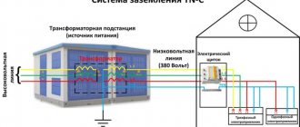
What is grounding
First of all, we need to define this term. Grounding is a specific connection of one point in the electrical network and with a grounding loop, which allows you to stabilize the voltage of electricity in the network by draining excess current into the ground with a suitable spreading resistance of the ground electrode. The electric line itself can exist without grounding. This is just a special protective measure that can prevent many accidents in a residential area.
By using grounding of household appliances and electrical installations, it is possible to provide safe conditions for their use by a person, protecting him from electric shock. When connecting grounding in buildings, several methods can be used: conventional, grounding to microelectronic circuits and to the “frame”. A prerequisite for grounding is the installation of a structure with electrodes that are inserted underground to a certain depth.
They must correspond to the spreading resistance of the ground electrode, which also includes the resistance of the contact itself between it and the ground. Their purpose is the final transfer of stray current from the system to the ground. The Electrical Installation Rules (PUE) contain a number of instructions and techniques for connecting the protective grounding loop of a house. This group of regulations is used by specialists during the design and drawing up of diagrams of the future system.
The quality of installation of special equipment is determined by measuring the resistance level. Ground resistance measurements must be carried out with certified instruments. Among the most common measuring instruments are considered to be models such as IS 10 and IS 20, as well as devices M416, F4103-M1. Today, protective grounding measures are considered very effective, as they have shown their effectiveness in practice. In most houses that are built according to new standards, the installation of a protective grounding loop is a prerequisite. The quality and reliability of its installation is checked by a group of specialists.
2.3.5 Measuring ground resistance using the three-wire method (3P)
Using the “Mode” button, select the three-wire measurement method, connect the minimum length measuring cable to the T1 socket. The measurement is carried out similarly to clause 2.3.4, but in this case the resistance of the measuring cable connected to the T1 socket will not be compensated (Figure 2.3.5).
Figure 2.3.5 Ground resistance measurement circuit
three-wire method
2.3.6 Measurement of soil resistivity (Rsp)
The value of soil resistivity is calculated using Werner's measurement method. This technique assumes equal distances between electrodes (d)
, which should be taken at least 5 times the immersion depth of the pins.
Install the measuring pins into the ground in a straight line, at equal distances (d)
and connect to the measuring sockets T1, P1, P2 and T2 in accordance with Figure 2.3.6.
Select the four-wire measurement method mode. Press the “Rx / ¿
” button and read the resistance value
RE
.
The soil resistivity is calculated using the formula: R beat = 2 π • d • RE (6.28 • d • RE).
Figure 2.3.6 — Connection diagram for measuring soil resistivity
To measure with automatic calculation of soil resistivity, use the “Mode” button to select the “R beat” mode, while the previously set distance between the pins is displayed on the indicator.
The distance between the pins can be changed in the “Menu” of the device. Select the function “SET. DIST." The message “DISTANCE BETWEEN ELECTRODES is XXm” appears. Use the ▲ or ▼ buttons to set the distance from 1 to 99 m in 1 m increments. To confirm the selected distance, press the “Rx / ¿
" Measuring soil resistivity is only possible using the four-wire method, which will turn on automatically. The measurement result will be displayed in “mOhm*m”, “Ohm*m” or “kOhm*m”.
The specified distance between the pins is stored in the device’s memory until new values are entered.
2.3.7 Measurements using clamps (if included in the device)
Connect clamps to sockets P1 and P2 (without observing polarity) and select the operating mode with clamps “mA” or “%”.
2.3.7.1 When choosing to measure alternating current “mA”, grasp the circuit under test with clamps. Press and hold the “Rx / ¿
" The device will measure the current and display the result on the screen.
2.3.7.2 Determining the percentage distribution of currents in multi-element grounding allows one to assess the quality of individual grounding devices, including failure (open circuit) of the circuit. A change in this parameter over time makes it possible to assess the nature and rate of aging associated with oxidation of the ground electrode or changes in the condition of the soil.
To determine the percentage distribution of currents through single grounding conductors in multi-element grounding, select this measurement mode “%”. If this operation is carried out without determining the total resistance, then the distance from the charger to the current pin for circuit T2 is selected according to the method of paragraph 2.3.4.
It is recommended to periodically calibrate the clamps before taking measurements. To do this, connect the T1 and T2 sockets to each other, and grab the shorting cable with pliers, select the “Caliber” function in the menu, briefly press the “Rx / ¿
"
The device will calibrate and the “READY” message will appear on the indicator. ¿
button again . However, if there is no contact in the T1T2 circuit or the clamps are not connected (faulty), the device will display a message, respectively, “NO CIRCUIT T1T2” or “NO SIGNAL P1P2”. The message “NO CIRCUIT T1T2” may also appear if the battery is severely discharged.
Connect the measuring leads and clamps according to Figure 2.3.7.2. Grasp a single grounding conductor with pliers, briefly press the “Rx / ¿
" The device will measure the current in the circuit under test, convert it into a percentage distribution and display the result on the screen. If there is no contact in the T1T2 circuit, the device will display the message “NO CIRCUIT T1T2”. Carry out a similar operation with other single grounding conductors.
Figure 2.3.7.2 Determination of percentage current distribution
through single grounding conductors
Attention! The RELIABILITY of measurements using clamps is inversely proportional to the soil resistivity and the number of single grounding conductors in a multi-element grounding.
After working with pliers, for the safety of the device, be sure to
switch to resistance measurement mode or turn off the device.
3 Maintenance and troubleshooting
Maintenance comes down to compliance with the rules of operation and storage.
The device uses a sealed, maintenance-free lead-acid battery with a nominal voltage of 12 V and a capacity of up to 0.8 A/h. Figure 3 shows the polarity of connecting the battery in the compartment.
Figure 3 - Battery connection polarity
The list of possible malfunctions and methods for eliminating them are given in Table 3.
Table 3 - List of possible faults and methods for their elimination
| Type of malfunction | Probable Cause | Elimination method |
| The device does not turn on | Battery is faulty or low | Check the condition of the battery, charge or replace it if necessary |
| The device does not measure resistance | Broken connecting cable, oxidation of contacts | Check the integrity of the cable, if necessary, repair or replace it, clean the contacts |
Repair of the device is permitted only at the manufacturer or specialized repair facilities.
4 Transportation and storage
The device is transported in standard packaging by all types of transport, except for leaky unheated compartments of the aircraft.
Climatic conditions of transportation and storage within the air temperature range from minus 50 to plus 70 ºС with relative air humidity not exceeding 95% at temperatures up to plus 30 ºС and atmospheric pressure from 70 to 106.7 kPa (from 537 to 800 mm Hg .). Exposure to precipitation is not allowed.
Disposal of the device is carried out by the operating organization and is carried out in accordance with the rules and regulations in force in the Russian Federation.
The device does not contain environmentally hazardous elements.
6 Verification
Primary and periodic verifications are carried out by state metrological service bodies or accredited metrological services of legal entities in accordance with PR 50.2.006. Periodic verification is carried out at least once a year, as well as after repairs.
What's included in the package
The is 10 device is equipped according to the list included in the package:
- IS-10 device – 1 pc.;
- user manual – 1 pc.;
- power supply unit BPN-A 12-0.5 – 1 pc.;
- clamp – 1 pc.;
- clamps – 2 pcs.;
- set of connecting cords: 2 pcs. 1.5 m each and 2 pcs. 40 m each (on a reel);
- storage case – 1 pc.;
- grounding electrode (L = 1 m) – 4 pcs.;
- current clamps – 1 pc.
Information. A set of electrodes and current clamps are optional elements of the kit. They are supplied separately. The external power supply may differ from the declared type, but has the necessary parameters.
Table 6.2 — Verification operations
| the name of the operation | Verification point number |
| 1 External inspection | 6.6.1 |
| 2 Testing | 6.6.2 |
| 3 Determination of the limit of the main relative error when measuring resistance | 6.6.3 |
| 4 Determination of the limit of the main relative error when measuring alternating voltage | 6.6.4 |
| 5 Determination of the limit of the main relative error when measuring alternating current (if there are clamps in the device) | 6.6.5 |
Note - In the case of a separate supply of KTI-10 clamps, the registration number is entered by the user into the acceptance certificate (clause 7) and an extraordinary verification of the device is carried out according to clause 6.6.5.
6.3 Verification means
When performing verification, the verification tools specified in Table 6.3 must be used.
Table 6.3 — Verification tools
| Name and type of verification tool | Required technical characteristics of the verification device |
| Resistance store P4834 | from 0.01 to 105 Ohm, up to 50 kHz, CT 0.02 |
| Installation U300 TU77 | up to 1000 V |
| Voltmeter V7-38 ХВ2.710.031TU | up to 1000 V, CT 0.4 |
| Device Ts4352 | Current up to 6 A, CT 1.0 for DC and 1.5 for AC |
Note - Equipment and measuring instruments can be replaced with similar ones that provide the required measurement accuracy of the relevant parameters and measurement limits.
Technical characteristics of IS-10
Force measuring device
The instruction manual that comes with the IS 10 has a section describing the technical parameters of the device. The main characteristics include:
- range of measured resistances, from 1 kOhm to 999 Mohm, with a resolution from 0.01 kOhm to 1 Mohm;
- relative measurement error under normal conditions (4-wire method):
δ = ± {[ 3 + 0.01 (Rк / Rх - 1)] % + 3 emr},
Where:
- emr – low-order unit,
- Rк – final value,
- Rx – the value of the desired resistance within the subrange.
- the ability to determine the amplitude of harmonic alternating voltage up to 300 V on both connectors P1 and P2;
- in combination with an electrical clamp (if available) – the ability to measure current up to 250 mA.
The IS-10 device circuit operates on a voltage of 10-14 V. There is a removable 12 V battery. When the battery discharges to 9.5 V, the device turns off automatically. You can recharge the battery from the power supply included in the kit. The charging indicator indicates that the battery is fully charged. Operating time before battery discharge is 4 hours.
Advice. No more than 3 minutes should pass from starting the device to the start of measurements, otherwise it will automatically turn off.