How can steel grounding bars be connected to each other?
Valery PUE clause 1.7.139.
Connections and connections of grounding, protective conductors and conductors of the equalization and potential equalization system must be reliable and ensure continuity of the electrical circuit. It is recommended to make connections of steel conductors by welding. It is allowed to connect grounding and neutral protective conductors in indoor and outdoor installations without aggressive environments in other ways that meet the requirements of GOST 10434 “Electrical contact connections. General technical requirements” for class 2 connections. Is it possible, according to the specified GOST, in other ways to connect steel grounding bars with an overlap, tightening them with steel square plates, tightened at the tops with 4 bolts? Answer: The question is not clear regarding the purpose of the steel grounding bus. In particular, it is not indicated whether the steel bus is a grounding conductor connecting the main busbar to the structure of the grounding device, and in what environment it is laid. The PUE, clause 1.7.139 talks about the recommended method of connecting steel conductors without additional measures for corrosion protection by welding. However, GOST R 50571.5.54-2013, clause 542.2.1, determines that the materials of grounding electrodes must provide corrosion and the necessary mechanical strength for the entire service life.
Based on Table 54.1 in GOST R 50571.5.54-2013, for grounding electrodes made of the most common materials in terms of corrosion and mechanical resistance, the following materials should be used: - hot-dip galvanized steel, stainless, in a copper sheath, with an electrochemical copper coating; — uncoated copper, tinned, galvanized.
GOST R 50571.5.54-2013, clause 542.3.2 defines methods for connecting the grounding conductor to the ground electrode using welding, crimping, connecting clamps, as well as other mechanical connectors. However, it should be noted that the mechanical connection must be installed in accordance with the manufacturer's instructions, and installation of the connection clamp must not result in damage to the electrode or grounding conductor.
In accordance with I1.03-08 “Instructions for the installation of protective grounding and potential equalization in electrical installations”, clause 2.2.13., it is recommended to connect the elements of grounding devices using special connectors, and when welding is used, measures must be taken to restore the anti-corrosion coverings.
Conclusion: 1. It is prohibited to use steel busbars without corrosion protection as a grounding conductor connecting the main grounding bus (GZB) with the structure of the grounding device. 2. Connections and connections of grounding busbars, protective conductors and equalization system conductors using special connecting clamps, subject to compliance with the manufacturer's instructions, ensure continuity of the electrical circuit and meet the requirements for ensuring the second class of connection according to GOST 10434.
GOST R 50571.5.54-2013/IEC 60364-5-54:2011 Low-voltage electrical installations. Part 5-54. Grounding devices, protective conductors and protective potential equalization conductors clause 542.2.1 Types, materials and sizes of grounding electrodes must provide corrosion and the necessary mechanical strength for the entire service life.
NOTE 1 From a corrosion perspective, the following factors may be considered: soil pH, soil resistivity, soil moisture, AC and DC stray and leakage currents, chemical contamination and proximity of incompatible materials.
The minimum dimensions of grounding electrodes made of the most common materials in terms of corrosion and mechanical resistance, laid in the ground and embedded in concrete are given in Table 54.1.
Note 2—The minimum thickness of the protective coating should be greater for vertical ground electrodes than for horizontal ground electrodes due to the greater mechanical stress when they are buried.
Table 54.1 - Minimum dimensions of grounding electrodes laid in the ground from the most common materials in terms of corrosion and mechanical resistance
542.2.8 If the ground electrode consists of parts that must be connected together, the connection must be made by exothermic welding, crimping, clamps or other approved mechanical connector.
Note—Connections made with iron-coated wire are not permitted for protection purposes.
clause 542.3.2 The connection of the grounding conductor to the ground electrode must be reliable and with appropriate electrical characteristics. The connection can be made by welding, crimping, connecting clamp or other mechanical connector. The mechanical connection must be installed in accordance with the manufacturer's instructions. Installation of the connection clamp must not result in damage to the electrode or grounding conductor. Soldered joints or soldered parts that rely solely on solder should not be used on their own as they do not provide the required mechanical strength. Note - If vertical electrodes are used, it must be possible to control the connection and replace the vertical rod.
I1.03-08 “Instructions for the installation of protective grounding and potential equalization in electrical installations”
clause 2.2.11. Connections of grounding electrodes, grounding and protective conductors in accordance with the requirements of clause 1.7.139 of the PUE must be made according to the second class of connections in accordance with GOST 10434 “Contact electrical connections. General technical requirements" (see appendix).
clause 2.2.12. When connecting elements of grounding devices made of different materials, measures should be taken to protect against electrochemical corrosion.
clause 2.2.13. It is recommended to connect the elements of grounding devices using special connectors; when welding is used, measures must be taken to restore the anti-corrosion coating.
Other and useful information
Source
Grounding
“ Grounding ” refers to the electrical connection of equipment and devices to a grounding device, which in turn is connected to the ground (earth). The purpose of grounding is to equalize the potential of equipment, circuits and ground potential. Grounding is mandatory for use at all power facilities to ensure the safety of workers and equipment from short circuit currents. When a breakdown occurs, the short-circuit current flows through the grounding device circuit to the ground. The current passage time is limited by the action of relay protection and automation. This ensures the safety of the equipment, as well as the safety of workers in terms of electric shock.
To protect electronic equipment from electrostatic potentials and limit the voltage of the equipment case for the safety of operating personnel, the resistance of an ideal grounding circuit should tend to zero. However, in practice this is impossible to achieve. Considering this circumstance, modern safety standards specify rather low permissible values of resistance of grounding circuits.
Grounding device resistance
The total resistance of the grounding device is composed of:
- The resistance of the metal of the electrode and the resistance at the point of contact between the grounding conductor and the grounding electrode.
- Resistance in the area of contact between the electrode and the ground.
- Ground resistance in relation to flowing currents.
In Fig. Figure 1 shows a diagram of the placement of a grounding electrode (pin) in the ground.
Figure 1. Grounding pin
As a rule, the grounding pin is made of a metal that conducts electric current (steel or copper) and is marked with the appropriate terminal. Therefore, for practical calculations, we can neglect the resistance value of the grounding pin and the point of contact with the conductor. Based on the results of the studies, it was found that if the installation technology of the grounding device is observed (close contact of the electrode with the ground and the absence of foreign impurities in the form of paint, oil, etc. on the surface of the electrode), due to its small value, it is possible to ignore the resistance at the point of contact of the grounding electrode with earth.
Soil surface resistance is the only component of the grounding device impedance that is calculated during the design and installation of grounding devices. In practice, it is believed that the grounding electrode is located among identical layers of soil, arranged in the form of concentric surfaces. The closest layer has the smallest radius and therefore the minimum surface area and the greatest resistance.
As you move away from the ground electrode, each subsequent layer increases its surface area and decreases its resistance. At some distance from the electrode, the resistance of the soil layers becomes so small that its value is not taken into account for calculations. The area of soil beyond which the resistance is negligible is called the area of effective resistance. The size of this area is directly dependent on the depth of immersion of the grounding electrode into the soil.
The theoretical value of soil resistance is calculated using the general formula:
where ρ is the value of soil resistivity, Ohm*cm. L – thickness of the soil layer, cm. A – area of the concentric surface of the soil, cm2.
This formula clearly explains why the resistance of each soil layer decreases with distance from the grounding electrode. When calculating soil resistance, its resistivity is taken as a constant value, but in practice the value of resistivity varies within certain limits and depends on specific conditions. Formulas for finding grounding resistance with a large number of grounding electrodes are complex and allow one to find only an approximate value.
Most often, the grounding resistance of a pin is determined using the classic formula:
where ρ is the average value of soil resistivity, Ohm*cm. R – electrode grounding resistance, Ohm. L – depth of the grounding electrode, cm. r – radius of the grounding electrode, cm.
Influence of the dimensions of the grounding electrode and the depth of its grounding on the value of grounding resistance
The transverse dimensions of the grounding electrode have little effect on the grounding resistance. As the diameter of the grounding pin increases, a slight decrease in grounding resistance is observed. For example, if the diameter of the electrode is doubled (Fig. 2), then the grounding resistance will decrease by less than ten percent.
Rice. 2. Dependence of the resistance of the grounding pin on the diameter of its cross-section, measured in inches
As the depth of placement of the grounding electrode increases, the grounding resistance decreases. It has been theoretically proven that doubling the depth can reduce drag by as much as 40%. In accordance with NEC (1987, 250-83-3), the pin should be immersed to a depth of at least 2.4 meters to ensure reliable contact with the ground (Figure 3). In many cases, a three meter grounded pin will fully satisfy current NEC standards.
According to NEC standards (1987, 250-83-2), the minimum permissible diameter of a steel grounding electrode is 5/8" (1.58 cm), a copper-clad steel electrode or copper electrode is 1/2" (1.27 cm) .
In practice, the following transverse dimensions of the grounding pin are used with a total length of 3 meters:
- Regular soil - 1/2" (1.27 cm).
- Wet soil - 5/8" (1.58 cm).
- Hard ground - 3/4" (1.90 cm).
- For a pin length of more than 3 meters – 3/4" (1.91 cm).
Rice. 3. Dependence of the resistance of the grounding device on the grounding depth (vertically - the value of the electrode resistance (Ohm), horizontally - the grounding depth in feet)
Influence of soil resistivity on the value of electrode grounding resistance
The above formula shows that the value of grounding resistance depends on the depth and surface area of the grounding electrode, as well as on the value of soil resistivity. The latter value is the main factor determining the grounding resistance and the depth of electrode grounding required to ensure minimum resistance. The resistivity of the soil depends on the time of year and the point on the globe. The presence of electrolytes in the soil in the form of aqueous solutions of salts and electrically conductive mineral substances greatly affects the soil resistance. In dry soil that does not contain soluble salts, the resistance will be quite high (Fig. 4).
Rice. 4. Dependence of soil resistivity (minimum, maximum and average) on the type of soil
Factors influencing soil resistivity
With extremely low moisture content (close to zero), sandy loam and ordinary soil have a resistivity of over 109 Ohm*cm, which allows such soils to be classified as insulators. An increase in soil moisture to 20 ... 30% contributes to a sharp decrease in resistivity (Fig. 5).
Rice. 5. Dependence of soil resistivity on moisture content
The resistivity of the soil depends not only on the moisture content, but also on its temperature. In Fig. Figure 6 shows the change in the resistivity of sandy loam with a moisture content of 12.5% in the temperature range of +20 °C to –15 °C. The resistivity of the soil when the temperature drops to – 15 °C increases to 330,000 Ohm*cm.
Rice. 6. Dependence of soil resistivity on its temperature
In Fig. Figure 7 shows changes in soil resistivity depending on the time of year. At significant depths from the surface of the earth, the temperature and humidity of the soil are quite stable and less dependent on the time of year. Therefore, a grounding system in which the pin is located at a greater depth will be more effective at any time of the year. Excellent results are achieved when the ground electrode reaches the groundwater level.
Rice. 7. Change in grounding resistance during the year.
A water pipe (¾") located in rocky soil was taken as a grounding device. Curve 1 (Curve 1) shows the change in soil resistance at a depth of 0.9 meters, curve 2 (Curve 2) - at a depth of 3 meters.
In some cases, an extremely high value of soil resistivity is noted, which requires the creation of complex and expensive protective grounding systems. In this case, you need to install a small grounding pin, and to reduce the grounding resistance, periodically add soluble salts to the surrounding soil. In Fig. Figure 8 shows a significant decrease in soil resistance (sandy loam) with increasing concentration of salts contained.
Rice. 8. Relationship between soil resistance and salt content (sandy loam with humidity 15% and temperature +17 °C)
In Fig. Figure 9 shows the relationship between the resistivity of the soil, which is saturated with a salt solution, and its temperature. When using a grounding device in such soils, the grounding pin must be protected from the effects of chemical corrosion.
Rice. 9. The influence of the temperature of soil impregnated with salt on its resistivity (sandy loam - salt content 5%, water 20%)
Dependence of the resistance value of the grounding device on the depth of electrode grounding
To determine the required depth of the grounding electrode, a grounding nomogram will be useful (Fig. 10). For example, to obtain a grounding value of 20 ohms in soil having a resistivity of 10,000 ohms*cm, it is necessary to use a metal pin with a diameter of 5/8" buried 6 meters.
Practical use of the nomogram:
- Set the required resistance of the grounded pin on the R scale.
- Mark the point of actual soil resistivity on the P scale.
- Draw a straight line to the K scale through the given points on the R and P scales.
- Mark a point at the intersection with the K scale.
- Select the required ground rod size using the DIA scale.
- Draw a straight line through the points on the K scale and on the DIA scale until it intersects the D scale.
- The intersection of this straight line with scale D will give the desired depth of the pin.
Rice. 10. Nomogram for calculating the grounding device
Measuring soil resistivity using the TERCA2 device
There is a large plot of land. The task is to find a place with minimal resistance and estimate the depth of the soil layer with the lowest resistivity. Among the various types of soil found in a given area, wet loam will have the least resistance. After a detailed examination of the site, the search area is narrowed to 20 m2. Based on the requirements for the grounding system, it is necessary to determine the soil resistance at a depth of 3 m (300 cm). The distance between the outermost ground pins will be equal to the depth for which the average resistivity is measured (in this case 300 cm).
To use the simplified Wenner formula
the grounding electrode should be at a depth of about 1/20 of the distance between the electrodes (15 cm).
The electrodes are installed according to a special diagram shown in Fig. 11. An example of connecting a grounding tester (Mod. 4500) is shown in Fig. 12.
Rice. 11. Installation of grounding electrodes along the grid
Next you should do the following:
- Remove the jumper that connects terminals X and X V (C1 and P1) of the measuring device.
- Connect the tester to each of the 4 pins (Fig. 11).
Example . The tester showed a resistance of R = 10 Ohms. The distance between the electrodes is A = 300 cm. The resistivity is determined by the formula ρ = 2 π *R*A
Substituting the initial data we get:
ρ = 2 π * 10 * 300 = 18,850 Ohm•cm.
Rice. 12. Tester connection diagram
Touch voltage measurement
The most important reason for measuring touch voltage is to obtain a reliable assessment of the safety of substation personnel and the protection of equipment from exposure to high voltage currents. In some cases, the degree of electrical safety is assessed according to other criteria.
Grounding devices in the form of a separate pin or array of electrodes require periodic inspection and verification of resistance measurements, which are performed in the following cases:
- The grounding device is compact in size and can be temporarily disabled.
- When there is a threat of electrochemical corrosion of the grounding electrode caused by low soil resistivity and constant galvanic processes.
- If there is a low probability of a breakdown to ground close to the grounding device being tested.
As an alternative way to determine the safety of substation process equipment, touch voltage measurement is used. This method is recommended in the following cases:
- If it is impossible to disconnect the grounding device to measure grounding resistance.
- In the event of a threat of ground faults near the grounding system being tested or in the vicinity of equipment connected to the grounding system being tested.
- When the circuit of the equipment in contact with the ground is comparable in area to the size of the grounding device to be tested.
It should be noted that measuring grounding resistance using the potential drop method or measuring touch voltage does not allow us to make a reliable conclusion about the ability of the grounding conductor to withstand significant currents when current leaks from the phase to the grounding conductor. For this purpose, a different method is required, in which a test current of significant magnitude is used. Touch voltage measurement is performed using a four-point ground tester.
In the process of measuring touch voltage, the device creates a small voltage in the ground, which simulates the voltage in the event of a fault in the electrical network near the point being tested. The tester shows the voltage value in volts per 1 A of current flowing in the ground circuit. To determine the highest touch voltage that can occur in an extreme case, multiply the resulting value by the maximum possible current.
For example, when testing a grounding system with the highest possible fault current of 3000 A, the tester returned a value of 0.200.
Therefore, the touch voltage will be
U = 3000 A * 0.200 = 600 V.
Measuring touch voltage is in many ways similar to the potential drop method: in each case it is necessary to install auxiliary ground electrodes in the ground. However, the distance between the electrodes will be different (Fig. 22).
Rice. 13. Grounding conductor diagram (general case for an industrial power supply network)
Let's consider a typical case. Near the substation, an underground cable suffered insulation damage. Currents will flow through this place into the ground, which will go to the substation grounding system, where they will create a high potential difference. High leakage voltage can pose a significant threat to the health and life of substation personnel located in a dangerous area.
To measure the approximate value of the touch voltage that occurs in this case, you should perform a number of steps:
- Connect the cable between the metal fence of the electrical substation and points P1 and C1 of the four-point grounding tester.
- Install a grounding electrode in the ground in the place where cable breakdown is most likely.
- Connect the electrode to input C2 of the tester.
- On the straight line between the first electrode and the point of connection to the fence, install an additional electrode in the ground. The recommended distance from the installation point of this electrode to the point of connection to the fence is one meter.
- Connect this electrode to point P2 of the tester.
- Turn on the tester, select the 10 mA range, record the device readings.
- To obtain the touch voltage value, multiply the tester readings by the maximum current value.
To obtain a voltage potential propagation map, it is necessary to install an electrode (of course, connected to the P2 terminal of the tester) in various places near the fence, located next to the faulty line.
Measuring grounding resistance with the “S.A.” device 6415" using current clamps
Measuring ground resistance using current clamps is a new, very effective method that allows measurements to be carried out while the grounding system is turned on. This method also provides a unique opportunity to measure the total resistance of a grounding device, including determining the resistance of connections in an existing grounding system.
Operating principle of the device S.A. 6415
Rice. 14. Grounding conductor diagram (general case for an industrial power supply network)
Rice. 15. Operating principle of the grounding conductor
A classic grounding device for an industrial electrical network can be presented in the form of a circuit diagram (Fig. 23) or in the form of a simplified diagram of the operation of the grounding conductor (Fig. 24).
If voltage E is applied to one of the sections of the circuit with resistance RX using a transformer, then electric current I will flow through this circuit.
These quantities are related to each other by the relationship:
By measuring the current I at a known constant voltage E, we can determine the resistance RX.
In the diagrams shown (Fig. 23 and 24), a special transformer is used to generate current, connected to a voltage source through a power amplifier (frequency 1.6 kHz, constant amplitude). The resulting current is recorded by a synchronous detector in the resulting circuit, further amplified using a selective amplifier and, after conversion through an analog-to-digital device, displayed on the device display.
The selective amplifier effectively clears the desired signal from spurious network signals and other high-frequency parasitic noise. To record the voltage level, coils are used that cover the conductor in the excited circuit. Next, the comparator compares the incoming signal with the reference signal. If the current clamps are connected incorrectly, the SA device 6415 displays the following message: “open jaws” (which means “the pliers are open”).
Typical examples of measuring ground resistance in real conditions
1. Measuring the grounding resistance of a transformer installed on a power line pole
Measurement procedure:
- Remove the protective cover from the grounding conductor.
- Provide the necessary space for the current clamp to freely reach the conductor or grounding pin.
- Clamps must be connected along the current path from the neutral or grounding wire to the grounding pin (pin system).
- Select current measurement “A” on the device.
- Grab the grounding conductor with a current clamp.
- Determine the current values in the conductor (the maximum permissible current is 30 A).
- If this value is exceeded, stop measuring the resistance.
- Disconnect the device from this point and take measurements at other points.
- If the current value does not exceed 30 A, you should select the “?” mode.
- The display of the device will show the measurement result in Ohms.
The resulting value includes the total resistance of the grounding system, which includes: the contact resistance of the neutral wire with the ground pin, as well as the local resistance of all connections between the pin and the neutral.
Rice. 16. Measuring ground resistance on a power line pole
Rice. 17. Measuring the grounding of a transformer installed on a power line support (grounding in the form of a group of pins)
Rice. 18. Measuring the grounding of a transformer installed on a power line support (a metal pipe is used for grounding)
According to the diagram shown in Fig. 25, the end of the pole and a pin located in the ground are used for grounding. To correctly measure the total grounding resistance, current clamps should be connected at a point located above the junction of the grounding conductors laid from the grounding pin and the end of the pole.
The reason for the increased ground resistance value may be:
- Poor grounding of the pin.
- Disconnected ground conductor
- High resistance values in the area of conductor contacts or at the splice point of the ground wire.
- You should carefully inspect the current clamps and the connections at the end of the pin to ensure that there are no significant cracks at the joints.
2. Measuring the ground resistance at the distribution box or electricity meter
The technique for measuring grounding on a distribution box and on an electric meter is similar to that discussed when measuring the grounding of a transformer. The grounding circuit can consist of a group of pins (Fig. 26) or a metal water pipe in contact with the ground can be used as a grounding conductor (Fig. 27). When measuring resistance grounding, both types of grounding can be used simultaneously. To do this, it is necessary to select the optimal point on the neutral in order to obtain the correct value of the total resistance of the grounding system.
3. Measurement of grounding resistance on a transformer installed on site
When carrying out grounding measurements at a transformer substation, you must remember:
- At this power facility there is always high voltage that is dangerous to human life
- The transformer enclosure must not be opened.
- All work may only be carried out by qualified specialists.
- When carrying out measurements, the requirements of safety and labor protection measures must be observed.
Rice. 19. Measuring the grounding value on a transformer located on a special site
Measurement procedure:
- Decide on the number of grounding pins.
- When the grounding pins are located inside the fence, measurements should be made according to the diagram shown in Fig. 28.
- When placing grounding pins outside the fence area, use the diagram shown in Fig. 29.
- If there is one grounding pin located inside the fence, you must connect to the grounding conductor at a point located after the contact of this conductor with the grounding pin.
- Using current clamps mod. The 3730 and 3710 connected directly to the ground pin will provide better measurement results in most cases.
- In many cases, several conductors are connected to the terminal on the pin, going to the neutral or into the fence.
- The clamp meter should be connected at the point where the only path for current to flow into the neutral conductor is.
If low resistance values are obtained, the measurement point should be moved as close as possible to the ground pin. In Fig. Figure 29 shows a grounding pin outside the barrier area. To ensure correct measurements, it is necessary to select the connection point for the current clamps in accordance with the diagram shown in Fig. 29. If there are several grounding pins inside the fence, you should determine their connection in order to select the optimal point for measurements.
Rice. 20. Choosing the correct ground measurement point
4. Transfer stands
When conducting grounding measurements on transmission racks, it should be remembered that there are many different configurations of grounding devices, which introduces certain difficulties when assessing grounding conductors. In Fig. Figure 30 shows a grounding diagram for a single rack on a concrete foundation with an external grounding conductor.
The connection point for the current clamps is selected above the connection point of the grounding elements, which can be designed in the form of a group of plates, pins, or represent structural elements of the rack foundation.
Figure 21. Measuring the ground resistance of the transmission rack
Connecting elements of grounding devices in the ground
When arranging grounding, it is necessary to connect wires to each other, as well as conductors and pins installed underground. Such connections must be resistant to corrosion and also require no maintenance over a long period of time. Currently, there are three main methods of connecting ground wires - crimping, welding and screw clamping. This article will provide a brief description of each method and compare their advantages and disadvantages.
Normative base
The connection of grounding wires is regulated by GOST R 50571.5.54-2013 (IEC 60364-5-54:2011) “Low-voltage electrical installations”. Part 5-54, paragraph 542.2.8: “If the grounding system consists of parts that are to be connected together, the connection must be made by exothermic welding, crimping, clamping or other approved mechanical connector.”
Another document regulating the connection of grounding wires is the PUE. P. 1.7.139, 7th edition of the PUE, in particular, states: “Connections and connections of grounding, protective conductors and conductors of the equalization and potential equalization system must be reliable and ensure continuity of the electrical circuit... Connections must be protected from corrosion and mechanical damage . For bolted connections, provisions must be made to prevent contact loosening.”
In addition, the parameters for connecting grounding wires with screw terminals are regulated by GOST 10434 “Electrical contact connections. General technical requirements". If there is no aggressive environment (earth, as a rule, does not belong to it), then the connections should belong to class 2. This includes contact connections of circuits whose conductor cross-sections are selected for resistance to through currents, voltage loss and deviation, mechanical strength and overload protection. Allows a clamp connection and circular 11/2006 of the Electrical Installation Association, if the connected elements are not made of ferrous metals.
3.3. Requirements for protective grounding 3.3.1. Products whose purpose does not require a method of protecting people from electric shock corresponding to classes II and III must be equipped with a grounding element. In this case, it is allowed to carry out the following products without a grounding element and not to ground them: those intended for installation in inaccessible places without the use of special means (including inside other products); intended for installation only on grounded metal structures, if this ensures stable electrical contact of the contacting surfaces and fulfills the requirement of clause 3.3.7; parts of which cannot be under alternating voltage higher than 42 V and under direct voltage higher than 110 V; grounding of which is not permitted by the principle of operation or purpose of the product.(Changed edition, Amendment No. 1, 3). 3.3.2. To connect the grounding conductor, welded or threaded connections must be used. By agreement with the consumer, the grounding conductor can be connected to the product by soldering or crimping performed by a special tool, device or machine. 3.3.3. Grounding clamps must comply with the requirements of GOST 21130-75. It is not allowed to use bolts, screws, or studs that act as fasteners for grounding. 3.2.2-3.3.3. (Changed edition, Amendment No. 1). 3.3.4. The bolt (screw, stud) for connecting the grounding conductor must be made of metal that is resistant to corrosion, or coated with metal that protects it from corrosion, and the contact part must not have surface coloring. (Changed edition, Amendment No. 4). 3.3.5. The grounding bolt (screw, stud) must be placed on the product in a place that is safe and convenient for connecting the grounding conductor. Near the place where the grounding conductor, provided for in clause 3.3.2, is to be connected, a grounding sign, applied in any way and indelible during operation, must be placed. The dimensions of the sign and the method of its implementation are in accordance with GOST 21130-75, and for lamps - in accordance with GOST 17677-82. There must be a contact pad around the bolt (screw, stud) for connecting the grounding conductor. The platform must be protected from corrosion or made of anti-corrosion metal, and not have surface painting. Measures must be taken against possible loosening of the contacts between the grounding conductor and the grounding bolt (screw, stud) (lock nuts, spring washers). The diameters of the bolt (screw, stud) and contact pad must be selected according to the current (see Table 1). Table 1 Nominal current of electrical equipment Nominal diameter of the thread for the place Diameter of the contact pad of the connection point, mm of the product, A connection, not less on the plane of the surface elevated relative to the surface St. 4 to 6 M 3 10 7 " 6 " 16 M 3.5 11 8 " 16 » 40 M 4 12 9 » 40 » 63 M 5 14 11 » 63 » 100 M 6 16 12 » 100 » 250 M 8 20 17 » 250 » 630 M 10 25 21 » 630 M 12 28 24 Notes: 1. On currents over 250 A, it is allowed to install two bolts instead of one, but with a total cross-section not less than the required one. When choosing the smallest bolt diameter for consumers and converters of electromagnetic energy, the current value should be taken as the current. consumed by the product from the source (network), for sources of electromagnetic energy - the value of the rated load current. 2. For electromagnetic energy sources having several rated currents, the bolt diameter should be selected based on the largest of these currents.
(Changed edition, Amendment No. 1, 3, 4). 3.3.6. If the dimensions of the product are small, and also if the grounding bolt (screw) is installed by welding its head, it is allowed to provide the necessary contact surface in connection with the grounding conductor using washers. The material of the washers must meet the same requirements as the material of the grounding bolt (screw, stud). (Changed edition, Amendment No. 3). 3.3.7. The product must have an electrical connection between all touchable metal non-current-carrying parts of the product that may be energized with grounding elements. The resistance value between the grounding bolt (screw, pin) and each accessible metal non-current-carrying part of the product, which may be energized, should not exceed 0.1 Ohm. 3.3.8. The following metal non-current-carrying parts of products subject to grounding must be equipped with grounding elements: shells, housings, cabinets; frames, frames, cages, racks, chassis, bases, panels, slabs and other parts of products that may become live if the insulation is damaged. It is allowed not to provide grounding elements for the following parts of the product (from those listed above): product bodies intended for installation on grounded switchboards, metal walls of switchgear chambers, in cabinets; non-current-carrying metal parts of the product that have electrical contact with grounded parts, subject to the requirements of clause 3.3.7; parts fixed in or passing through insulating material and isolated from both grounded and live parts (provided that during operation of the product they cannot become live or come into contact with grounded parts). 3.3.9. Each part of the product equipped with an element for grounding must be designed in such a way that: it is possible to independently connect it to a ground electrode or grounding line through a separate branch, so that when any grounded part of the product is removed (for example, for routine repairs) the grounding circuit of other parts were not interrupted; there was no need to connect several grounded parts of the product in series. 3.3.10. Grounding of parts of products installed on moving parts must be done with flexible conductors or sliding contacts. 3.3.11. If there is a metal shell, the element for grounding it must be located inside the shell. It is possible to perform it outside the shell or to perform several elements both inside and outside the shell. (Changed edition, Amendment No. 1). 3.3.12. Electrical contact between the removable and grounded (non-removable) parts of the shell must be achieved by directly pressing the removable part against the non-removable part; at the same time, in places of contact, the surfaces of the removable and non-removable parts of the shell must be protected from corrosion and not covered with electrically insulating layers of varnish, paint or enamel. It is allowed to electrically connect the removable part of the shell with the non-removable grounded part through the screws or bolts securing it, provided that 1-2 screws or bolts have an anti-corrosion metal coating, and between the heads of these screws or bolts and the removable metal part of the shell there is no electrically insulating layer of varnish, paint, enamels or between them, serrated washers are installed that destroy the electrical insulating layer to make an electrical connection or without serrated washers, provided that the removable part is attached to a non-removable grounded one with six or more bolts (or screws) and there is no electrical connection on the removable parts of electrical devices. It is also permissible to use toothed washers for the electrical connection of the grounded shell and equipment mounted in the product, and to install them for grounding the elements of the product through bolted connections. (Changed edition, Amendment No. 3). 3.3.13. The requirements listed in clause 3.3 do not apply to products intended for use only in areas with a tropical climate and made in accordance with GOST 15151-69, GOST 9.048-89.
Crimping
Connecting wires by crimping is the simplest and most technologically advanced method. The wires are inserted from both sides into the sleeve and crimped with a special device called a crimper. However, this method is not suitable for connecting a wire to a ground pin. In addition, if the crimp connection is located underground, the sleeve and wires are covered with a layer of oxide, which increases the contact resistance. Sealing of such a connection is used, but in the end such sealing is a complex and unreliable solution. In fact, the rules of the PUE cannot be fully complied with. This is why crimping cannot be used for connections located underground.
Welding
Currently, GOST does not mention arc welding among the methods acceptable for connecting ground wires
There are two main types of welding - electric arc and exothermic. During electric arc welding, the temperature reaches +7000°C, which causes the destruction of the protective anti-corrosion layer. In addition, intense heat weakens not only the coatings, but also the metals from which the cores of the conductors are made. So-called intergranular corrosion occurs, which can potentially lead to destruction of the connection. That is why GOST R 50571.5.54-2013 does not include arc welding among the acceptable methods for connecting grounding conductors.
Set for exothermic conductor welding
Instead of arc welding, so-called exothermic (sometimes also called thermite) welding is now used to connect grounding wires. In exothermic welding, the so-called thermite, a powdered mixture of aluminum or magnesium with iron scale (or copper oxide), is used to heat the metal. For the ground loop, aluminum and copper oxide thermite are typically used. The joint is molded with refractory material, a powdered thermite composition is poured there, which is then set on fire. As a result of thermite combustion, liquid copper is formed, which has good adhesion to the materials being welded. The melt temperature exceeds 3000°C. Exothermic welding complies with the standards of both GOST R 50571.5.54-2013 and PUE.
You can see how exothermic welding is carried out in the video:
Ready-made kits for exothermic welding are available, the use of which does not require special training. However, other things being equal, the use of exothermic welding is still more complicated than connecting wires with screw terminals. Naturally, special requirements are imposed on screw terminals suitable for connecting ground wires.
How to properly connect a wire in a junction box
The most controversial and painful problem during electrical installation work is the connection of wires and cables in the junction box. Electricians weld, sleeve (crimp), solder, use various clamps (pads, clamps, terminals, PPE - connecting insulating clamps), twist. How many electricians, so many different opinions.
What do the rules for connecting wires and cables say?
We will use several sources that are relevant today. PUE-7 (Rules for electrical installations), SNiP 3.05.06-85 (Electrical devices), GOST R 50571.5.52-2011. (Low-voltage electrical installations).
PUE-7 Chapter 2.1
Section: Electrical wiring
2.1.21. Connection, branching and termination of wire and cable cores must be carried out using crimping, welding, soldering or clamping (screw, bolt, etc.) in accordance with current instructions approved in the prescribed manner.
2.1.22. At the points of connection, branching and connection of wire or cable cores, a supply of wire (cable) must be provided, ensuring the possibility of re-connection, branching or connection.
SNiP 3.05.06-85
Electrical installation work
Section: Electrical wiring
3.34. All connections and branches of installation wires must be made by welding, crimping in sleeves or using clamps in branch boxes.
Metal branch boxes where wires enter them must have bushings made of insulating materials. It is allowed to use pieces of polyvinyl chloride tube instead of bushings. In dry rooms, it is allowed to place wire branches in sockets and niches of walls and ceilings, as well as in ceiling voids. The walls of the sockets and niches must be smooth, the branches of the wires located in the sockets and niches must be covered with covers made of fireproof material.
GOST R 50571.5.52-2011.
526 Electrical connections
526.2 When choosing means of connection, the following should be considered:
— conductor material and its insulation;
- the number and shape of wires forming the conductor;
- cross-sectional area of the conductor;
- the number of conductors that will be connected together.
Notes:
1 The use of solder connections is recommended to be avoided, except for communication circuits. If such connections are used, they must be made taking into account possible displacements, mechanical forces and temperature increases due to short circuits.
Expanded comment
We have reviewed all regulations governing the connection of wires. Let's look at the advantages and disadvantages.
Crimping (sleeving)
All standards recommend
Very high quality connection, large contact area. There is perhaps only one drawback: the sleeve is large in size and you have to make large distribution boxes, which affects the design of the room.
Sleeve, twist and terminal Vago
Photo and brief description
On the left in the photo is a connection made using a sleeve. The wires are inserted into a tinned sleeve and crimped with a special press. If the sleeve is chosen correctly, the connection turns out to be very good. There is a twist in the center, if done as in the photo it will be no worse than the sleeve, but it is prohibited by the rules, we do not use it in our work. On the right is an attempt to repair the wiring with the help of Vaga, the connection got hot, the terminal melted, and it’s not far from a fire.
Welding
All standards recommend
Good contact, small dimensions. The disadvantage is that it is problematic to weld the connection of a large number of wires without damaging the insulation (very strong heating).
Soldering
It prescribes the use of only PUE, SNiP is silent, and GOST generally recommends avoiding connections using soldering.
It is quite difficult to properly solder even two wires, but if successful, the connection will be of high quality. It is practically impossible to solder five, six or more wires, especially under the ceiling or in a hard-to-reach place where most customers ask to put a junction box so that it is not an eyesore.
Twist
Although no one has come up with a better idea yet. The wires are always twisted first, and then boiled, soldered, or crimped. I will not agitate, we will follow the rules, twisting in its pure form is PROHIBITED!
PPE, Vago terminal and screw clamp
Photo and brief description
On the left in the photo is a connection made using PPE. The wires are first twisted, which in itself is not bad, and the cap is screwed on top in full accordance with the rules. In the center of Vaga (with hoisting flags is considered the best option), it worked under load for about two years, melted plastic and insulation. On the right is a screw clamp, the problem is the same as with Vaga, the connection gets hot, the consequences are unpredictable
Squeezes
All standards recommend
There are a lot of different wire clamps, all of them are certified, but, unfortunately, they have different quality.
The most common Wago terminals: installation is quick, looks beautiful, but cannot withstand long-term loads close to the maximum. Ours only in the case of work on an agreed project, where the model of connecting terminals is clearly stated. Thus, we relieve ourselves of responsibility in the event of an emergency, shifting it to the designer and manufacturer of the terminals.
Screw clamps: A high-quality connection is obtained only with clamps where there is an additional blade under the screw, and if the screw is screwed directly into the wire, expect it to burn over time.
PPE (Connecting Insulating Clamp): When used in its pure form, the problem is the same as with welding and soldering, clamping a large number of wires. But if we first twist it, twenty to twenty-five millimeters, and then twist the PPE on top, the result is excellent. The connection is not subject to heating, which has a positive effect on further operation. We have been using this method for more than fifteen years and have not had a single complaint. There is only one drawback: a bare neck sticks out from under the PPE, which needs to be further insulated. Therefore, the method is not as aesthetic as; “Wago” terminals, but the connection is very good, the contact area significantly exceeds the cross-section of the conductor.
Screw terminals
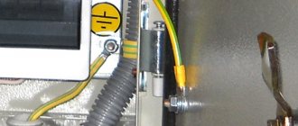
In order to realize the advantages of ready-made ZANDZ grounding kits, namely, extreme ease of assembly and installation, it makes sense to use screw clamps. If an error is made during assembly, you can disassemble and then reassemble correctly. But even if your qualifications and experience allow you to do everything correctly right away, it is still easier to work with screw clamps than to use welding.
But screw clamps have two drawbacks, which, however, can be overcome. Firstly, when they connect a copper-plated grounding pin and a wire made of ordinary steel or galvanized steel, an electrochemical reaction occurs, leading to corrosion. Secondly, over time, loosening of the tightening of the screws may occur, to which special attention is paid in the PUE.
Source
How to properly make a ground loop in a private house - circuit calculation and installation
Issues of grounding in a private house, circuit calculations and system installation require a mandatory solution to ensure the safety of living. Grounding will perform its full functions only if the circuit is selected correctly and all standards and requirements are observed. Self-installation requires knowledge of design principles and manufacturing rules.
Grounding of individual devices
The installation of some devices in a private home inevitably involves the need to comply with safety rules. For example, a gas boiler must be grounded.
Often the cause of electric shock is static discharges on the surface of the metal casing of the heating device. In addition, electricity can cause a fire in the gas under pressure in the boiler.
Unlike many appliances, a gas boiler is grounded only by creating an artificial circuit.
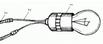
Useful tips Connection diagrams Principles of operation of devices Main concepts Meters from Energomer Precautions Incandescent lamps Video instructions for the master Testing with a multimeter
Is grounding necessary in a private house?
When using any electrical appliances in the house, there is always a risk of damaging the insulation of the wires or shorting them to the housing. In this case, any person touching the dangerous zone leads to electric shock, which can end tragically. The current always tends to the ground, and the human body becomes a conductor connecting the damaged device to the ground.
What does grounding do? Essentially, it is a system that provides the shortest path for electrical current. According to the law of physics, he selects the conductor with the lowest electrical resistance, and the circuit has this property. Almost all the current is directed to the ground electrode, and therefore only a small part of it will pass through the human body, which cannot cause harm. Thus, the ground loop ensures electrical safety. Regulatory documents (GOSTs, SNiP, PUE) indicate that any private, residential building must be equipped with it for alternating current networks with voltages above 40 V and alternating current networks with voltages above 100 V.
In addition to ensuring safety, the grounding system increases the reliability and durability of household appliances. It ensures stable operation of installations, protection against overvoltage and various network interferences, and reduces the impact of external sources of electromagnetic radiation.
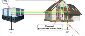
Grounding should not be confused with lightning rods (lightning rods). Although the principle of their operation is similar, they perform different tasks. The job of a lightning rod is to divert lightning into the ground when it hits a house. In this case, a powerful electric charge arises, which should not enter the internal network, because can simply melt a wire or cable. That is why the lightning rod line runs from the receivers on the roof along the outer contour and should not be combined with the grounding, internal line. The lightning rod and grounding may have a common underground circuit (if it has a margin in cross-section), but the wiring must be separated.
Grounding schemes: which one is better to make?
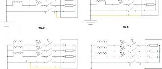
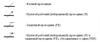
The grounding system of a private house depends on the type of network connection to it. Most often, it is performed according to the TN-C principle. Such a network is provided by a two-core cable or two-wire overhead line at a voltage of 220 V and a four-core cable or four-wire line at 380 V. In other words, a phase (L) and a combined protective neutral wire (PEN) are supplied to the house. In full-fledged, modern networks, the PEN conductor is divided into separate wires - working or neutral (N) and protective (PE), and the supply is carried out by a three-wire or five-wire line, respectively. Taking into account the above options, the grounding scheme can be of 2 types.
TN-CS system
Provides for dividing the PEN input into parallel conductors. To do this, in the input cabinet the PEN conductor is divided into 3 buses: N (“neutral”), PE (“ground”) and a splitter bus for 4 connections. Further, conductors N and PE cannot contact each other. The PE bus is connected to the cabinet body, and the N-conductor is installed on insulators. The grounding circuit is connected to the bus splitter. A jumper with a cross-section of at least 10 sq. mm (for copper) is installed between the N-conductor and the ground electrode. In further wiring, “neutral” and “ground” do not intersect.
Reference! It is important to consider that this system is effective only when installing an RCD and a differential-type circuit breaker.
TT system
In such a circuit, it is not necessary to split the conductors, because the neutral and earth conductors are already separated in a suitable network. The cabinet simply makes the correct connection. The grounding circuit is connected to the (residential) PE wire.
How to do grounding correctly in an apartment
To answer this question, you need to understand what kind of protection system is installed in your home.
As a rule, in old Soviet-built houses the TN-C System , in which the neutral protective and neutral working conductors are combined into one PEN conductor, and they are combined throughout the entire system. You can recognize such a system by the two-core cable that is laid around the apartment and by the four-core cable in the common panel.
To be honest, how to properly do grounding in an apartment in an old building, then such a system only protects against short circuits and increases the likelihood of receiving an electric shock. Therefore, talking about protective grounding in this case is necessary with a certain degree of risk. There are several working options that reduce risks, but are not complete protection, and are done at your own peril and risk.
Option 1 We change the wiring in the apartment to three-wire L, N, PE, but do not connect PE anywhere. In the future, when the common house grounding is done, it will be possible to connect. We must install an RCD on groups of sockets in case of phase contact with the housing within the apartment. They do not guarantee absolute protection. But if household appliances are damaged, the RCD will de-energize the line and prevent the current from reaching dangerous levels.
Option 2 We agree with the neighbors and the management company and make a separate grounding loop near the entrance according to the same principle as in a private house. This option is the safest and most correct.
Option 3 We leave zero as is, take the PE wire from the main PEN wire. You can do it from the place where it fits the body of the floor panel. It is important that our N and PE are connected at different points. PE – on the body, N – on a bus isolated from the body, to which zero comes after the input switch or machine and the meter. However, there remains a big disadvantage in this decision. The zero may burn out at the entrance to the house. You may think that there are fewer houses than apartments and the likelihood of such a problem occurring is less, but this danger is still there. Therefore, such grounding does not work 100%.
What is a ground loop: definition and device
A grounding loop is a special design made of electrically conductive materials with low electrical resistance, providing instant drainage of electric current to the ground. It consists of 2 interconnected parts - an internal and external system. Their reliable connection is carried out in the input electrical panel.
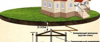
The design of the external subsystem must ensure the transition of the electrical signal to the ground with its distribution over the area. It is based on several electrodes buried in the ground and connected to each other in a circuit using plates. A bus of sufficient cross-section extends from the plates, which is inserted into the electrical panel, where it is connected to the internal subsystem. Each electrode is a metal pin buried (driven in) to a certain depth.
The internal subsystem is the distribution of the grounding circuit throughout the house. Conductors from the switchboard are routed to sockets, to the housings of powerful electrical devices, and to metal mains (pipes). The individual conductors are combined into a common bus, which is connected to the external circuit bus.
The principle of operation of the ground loop is quite simple. The electric charge accumulated in metal elements (installation housings, pipelines, fittings, etc.) when the insulation of the electrical network conductors is damaged or induced from external sources, rushes through the wires of the internal subsystem, which have low electrical resistance, to the circuit of the external subsystem. It “flows” into the ground through electrodes buried in the ground. In turn, the earth has a huge capacity, which allows it to freely “absorb” such electricity leaks.
How to make a ground loop
A grounding device, or grounding loop, consists of several metal pins (electrodes) that are connected to each other at one end and buried in the ground at the other end. Typically, “at-home” electrodes are made from reinforcement or angle steel. Less often - from pipes. How to make, drive into the ground and connect such pins together can be seen in the video.
https://youtube.com/watch?v=JV243D9zZWk
The ground loop most often has the shape of a square or triangle (diagram). Electrodes must be no shorter than 2.5 meters. The edges of the grounding loop must either be equal to or be a multiple of them. For example, if the length of the electrode is 2.5 meters, then the edges of the circuit should be either 2.5 or 5 meters. The optimal length of the electrode pins is 2.5-3 meters.
Accordingly, the grounding loop may have the following parameters: its sides must be in relation to either 2.5 x 2.5 or 3 x 3. The square is sometimes made slightly larger (4 x 4 m). It is advisable to sharpen the electrodes at one end. This will make it easier to drive them into the ground. The pins are welded together into a circuit only after they are buried in the ground.
The process of installing a ground loop looks like this:
1. First, next to the house, you need to dig a trench in the shape of the future contour (square or triangular). Its depth should be 70-80 cm.
2. We cut the reinforcement into pins of equal length 2.5-3 m. We drive them into the corners of the trench, as in the video. Be sure to leave small parts of the electrodes above the ground.
3. The tops of the electrodes are connected to each other by steel strips. This can be done by welding.
4. A steel strip is welded to one of the corners, which must be brought to the wall of the building.
5. A bolt must be welded to the end of the steel strip using the same electric welding.
6. The 220 V grounding cable coming out of the house is attached to the bolt welded in this way. The fastening can be done as follows: roll the cable into a loop and simply put it on the bolt. A nut and washer are placed on top of it and tightened tightly.
7. After this, the trench with the grounding loop just needs to be covered with earth.
8. The cable is connected, as mentioned earlier, to the grounding bus in the distribution board.
Please note: The conductor cross-section must be more than 75 square meters. mm
Only in this case will grounding be effective and last a long time.
Types of ground loops
To quickly “drain” the current into the ground, the external subsystem redistributes it to several electrodes located in a certain order to increase the dissipation area. There are 2 main types of circuit connections.
Triangle - closed loop
This case involves the use of 3 pins connected by stripes into an isosceles triangle. The distance between the electrodes is selected according to the following principle: the minimum distance is the length of the underground part of the electrode (depth), the maximum is 2 depths. For example, for a standard depth of 2.5 m, the side of the triangle is selected within 2.5-5 m.
Linear
This option is made up of several electrodes arranged in a line or in a semicircle. An open contour is used in cases where the area of the site does not allow the formation of a closed geometric figure. The distance between the pins is selected within 1-1.5 depth. The disadvantage of this method is the increase in the number of electrodes.
These types are most often used when arranging the grounding of a private house. In principle, a closed loop can be formed in the shape of a rectangle, polygon or circle, but a larger number of pins will be required. The main advantage of closed systems is that they continue to function fully when the connection between the electrodes is broken.
Important! The linear circuit operates on the principle of a garland and damage to the jumper puts a certain section of it out of service.
What should be the grounding resistance?
One of the main performance criteria for any protective grounding facility is the grounding resistance. This value shows the resistance to the unhindered spread of electric current in the layers of the earth entering the soil through a protective device - a ground electrode.
At best, this resistance indicator is zero. At this value, the electric current is completely absorbed. In practical terms, such an indicator is impossible to achieve. For proper operation of electrical equipment and reliable protection of citizens, a final value of 0.5 Ohm is allowed for the entire protective device.
Rules and requirements for the ground loop
In order for the ground loop to work effectively, it must comply with certain rules:
- The external contour should be located at a distance of at least 1 m and no more than 10 m from the house. The optimal distance is 2-4 m from the foundation.
- The depth of the electrodes is selected within 2-3 m. A part of the pin 20-25 cm long is left on the surface for connection with a strip.
- A bus with a cross-section of at least 16 square meters is laid from the input panel to the circuit. mm.
- The connection of the electrodes to each other is ensured only by welding. The connection in the panel can be made with bolts.
- The total system resistance should not exceed 4 ohms for 380 V and 8 ohms for 220 V.
The external ground loop is located in the ground, which implies increased requirements for its design. It should be located below the soil freezing level, because heaving of the soil will push the electrodes out. During operation, corrosion should not destroy the metal and excessively increase its electrical resistance. The strength of the rods should allow them to be driven into hard ground.
Bolted grounding connection PUE
Explain the requirements of PUE 7, Chapter 1.7 and GOST R 58882-2020 regarding the selection of the cross-section of the equalization conductor when connecting GZSh buses in the presence of several built-in transformer substations.
GOST R 58882-2020 clause 7.6.4.4.
If the building has several separate inputs, the main grounding bus must be made for each input device. If there are built-in transformer substations, the main grounding bus must be installed near each of them. These buses must be connected by a potential equalization conductor, the cross-section of which must be at least half the cross-section of the PE (PEN) conductor of the line among the substations extending from the low-voltage switchboards that has the largest cross-section.
GOST R 58882-2020 p 7.6.6.13
The cross-section of the conductors of the main potential equalization system must be at least half the largest cross-section of the protective conductor of the electrical installation, if the cross-section of the potential equalization conductor does not exceed 25 mm 2 for copper or equivalent to it from other materials. The use of conductors of larger cross-sections is, as a rule, not required.
PUE 7.chl.7 p.1.7.120.
If the building has several separate inputs, the main grounding bus must be made for each input device. If there are built-in transformer substations, the main grounding bus must be installed near each of them. These buses must be connected by a potential equalization conductor, the cross-section of which must be at least half the cross-section of the PE (PEN) conductor of the line among the substations extending from the low-voltage switchboards that has the largest cross-section. The cross-section of this conductor should be no more than 25 mm 2 for copper or equivalent from another material. Third-party conductive parts may be used to connect multiple main ground bars if they meet the electrical continuity and conductivity requirements of 1.7.122.
PUE clause 1.7.120 indicates the use of a conductor with a cross section of 25 mm 2.
GOST R 58882-2020 clause 7.6.6.13 prescribes the use of a conductor with a cross-section of no more than 25 sq. mm (it is indicated that the use of conductors with a larger cross-section, as a rule, is not required).
At the same time, GOST R 58882-2020 clause 7.6.4.4 prescribes the connection of the GZSh with a conductor, the cross-section of which must be at least half the cross-section of the PE (PEN) conductor of the line among the substations extending from the low-voltage switchboards that has the largest cross-section. Accordingly, when applying clause 7.6.4.4. The cross-section of the conductor for connecting the GZSh will in some cases be significantly larger than 25 mm 2.
The requirements for the basic potential equalization system are set out in Chapter 1.7. Rules for the Construction of Electrical Installations (PUE, 7th edition, Chapter 1.7, approved by Order of the Ministry of Energy of Russia dated July 8, 2002 No. 204).
In accordance with clause 1.7.120 of the PUE “If a building has several separate inputs, the main grounding bus must be made for each input device. If there are built-in transformer substations, the main grounding bus must be installed near each of them. These buses must be connected by a potential equalization conductor, the cross-section of which must be at least half the cross-section of the PE (PEN) conductor of the line among the substations extending from the low-voltage switchboards that has the largest cross-section. Third-party conductive parts may be used to connect multiple main ground bars if they meet the requirements of 1.7.122 for electrical circuit continuity and conductivity."
Similar provisions are contained in clause 7.6.4.4 of the National Standard GOST R 58882-2020 “Grounding devices. Potential equalization systems. Grounding electrodes. Grounding conductors. Technical requirements”, approved by Order of the Federal Agency for Technical Regulation and Metrology dated June 16, 2020 No. 254-st: “... If the building has several separate inputs, the main grounding bus must be made for each input device. If there are built-in transformer substations, the main grounding bus must be installed near each of them. These buses must be connected by a potential equalization conductor, the cross-section of which must be at least half the cross-section of the PE (PEN) conductor of the line that has the largest cross-section among those extending from the low-voltage substations switchboards. Third-party conductive parts may be used to connect several main ground bars if they meet the requirements for continuity and conductivity of the electrical circuit.”
Thus, the GZSh must be connected by a potential equalization conductor, the cross-section of which must be at least half the cross-section of the PE (PEN) conductor of that line, among the built-in substations extending from the 0.4 kV switchgear, which has the largest cross-section. The cross-section of such a conductor for connecting the GZSh will in some cases be significantly larger than 25 mm 2.
Clauses 1.7.120 and 1.7.122 of the PUE do not indicate the use of potential equalization conductors only with a cross-section of up to 25 mm 2.
The requirements of clause 1.7.137 of the PUE and the provisions of clause 7.6.6.13 of GOST R 58882-2020 indicate that the use of conductors with a cross-section exceeding 25 mm 2 “as a rule, is not required,” that is, it is not required in the absence of appropriate (in in specially specified cases) instructions.
The requirements of clause 1.7.120 of the PUE and the provisions of clause 7.6.4.4 of the National Standard GOST R 58882-2020 are the corresponding instructions (specially selected case).
When making technical decisions on the installation of a potential equalization system, one should be guided by the mandatory requirements of the PUE, interstate standards, technical documentation of manufacturers, taking into account the recommendations of national standards and codes of practice.
Grounding calculation for a private house: formulas and examples
Grounding calculations for a private home are based on formulas for calculating the resistance to current spreading for electrodes. Examples will be shown below.
Soil resistance
For a single rod, the formula is applied:
where ρ eq is the equivalent resistivity of a single-layer soil (selected according to Table 1 for a specific soil);
- L—electrode length (m);
- d—electrode diameter (m);
- T is the distance from the middle of the electrode to the ground surface (m).
| Priming | ρ eq, Ohm m |
| Peat | 20 |
| Soil (chernozem, etc.) | 50 |
| Clay | 60 |
| Sandy loam | 150 |
| Sand with groundwater up to 5 m | 500 |
| Sand with groundwater deeper than 5 m | 1000 |
Dimensions and distances for ground electrodes
The number of electrodes in the circuit can be calculated using the formula, where:
Rн is the maximum permissible total circuit resistance (for a network of 127-220 V - 60 Ohms, for 380 V - 15 Ohms), Ψ - climatic coefficient (determined according to Table 2).
| Electrode type | Climate zone | |||
| I | II | III | IV | |
| Vertical rod | 1.8 ÷ 2 | 1.5 ÷ 1.8 | 1.4 ÷ 1.6 | 1.2 ÷ 1.4 |
| Horizontal stripe | 4.5 ÷ 7 | 3.5 ÷ 4.5 | 2 ÷ 2.5 | 1.5 |
Electrode sizes are selected taking into account actual conditions and recommendations:
- pipe - minimum wall thickness 3 mm, diameter - depending on the availability of material;
- steel bar - diameter not less than 14 mm;
- corner - wall thickness 4 mm, size - according to the availability of material;
- strip for linking electrodes - width - at least 10 mm, thickness - more than 3 mm.
The depth of penetration (length of the electrodes) is selected from the condition - at least 15-20 cm below the freezing level. The minimum length is 1.5 m. The pin installation step is 1-2 times the length of the electrode, and the minimum distance is 2 m.
Ground strip weld length
3.1.12.
When installing the external circuit, the following operations are performed: - mark the circuit route and the places where the electrodes are buried in the ground;
— bury vertical electrodes into the ground;
— lay horizontal electrodes in the trench and use them to connect the vertical electrodes to each other. For in-depth grounding conductors, horizontal grounding conductors are laid at the bottom of the pits along the perimeter of the building foundation and connected to each other;
— inspect the external circuit and check the quality of the connection and draw up a report for hidden work;
— fill up the trench (pit);
— measure the resistance to current flow in the outer circuit.
3.1.13. Marking is carried out based on working drawings. In this case, the distance between the vertical electrodes must be at least 1.5-2 times the length of the electrode, which eliminates mutual shielding and, therefore, helps reduce the resistance to current spreading. The distance from the foundation of the building to parts of the ground electrode must be at least 2.5 m. This requirement does not apply to in-depth ground electrodes.
3.1.14. It is not allowed to place grounding electrodes in places where the ground is dried out by the heat of pipelines, etc., in places where there is a high risk of corrosion of the grounding electrode.
3.1.15. Trenches for vertical grounding conductors are torn to a depth of 0.5-0.7 m. After the vertical electrodes are buried in the ground, the upper end should protrude 0.1-0.2 m above the bottom of the trench. Horizontal electrodes are laid at the bottom of the trench at a depth of 0.5 -0.7 m.
3.1.16. For artificial grounding conductors, steel should be used. The dimensions of steel artificial grounding conductors must be no less than:
— diameter of round non-galvanized ones — 10 mm; galvanized - 6 mm;
- rectangular cross-section - 48 mm 2;
— rectangular thickness — 4 mm;
— the thickness of the corner steel shelves is 4 mm.
Artificial grounding conductors should not be painted.
3.1.17. The ground electrode ensures contact of the grounding device with the ground. The deeper the ground electrode is buried in the ground, the less, as a rule, its resistance to current spreading will be. The length of the vertical grounding rod electrodes should be 4.5-5 m, and the angle steel electrodes should be 2.5-3 m.
3.1.18. The connection of all elements of the ground electrode to each other, as well as connection to natural ground electrodes, is performed by welding. The length of the weld should be equal to twice the width of the conductor for a rectangular cross-section and six diameters for a round cross-section. In a T-shaped connection with an overlap of two strips, the length of the overlap is determined by the width of the strip. Examples of connections of rod electrodes with grounding conductors and connections to pipelines are presented in Figures 3.1.1 and 3.1.2.
Rice. 3.1.1. Connection of rod electrodes with grounding conductors (weld length 6d):
A
,
b
- made of round steel;
c
,
d
- from strip steel
1
— rod electrode;
2
- grounding conductor made of round steel;
3
- grounding conductor made of strip steel;
4
- strips made of strip steel (used for B ≤ 3 mm).
Rice. 3.1.2. Examples of connecting grounding conductors to pipelines:
A
,
b
,
c
- welding;
g
- using a clamp:
1
— grounding conductor made of strip steel;
2
- pipeline;
3
- grounding conductor made of round steel;
4
- clamp.
3.1.19. The connection of grounding conductors to the pipeline used as a natural grounding conductor must be carried out before the pipe is inserted into the building (to the water meter, valves, flanges), otherwise bypass jumpers made of strip steel with a cross-section of at least 100 mm 2 must be installed above the water meters, valves, flanges. . The jumper is connected to the pipes by welding or clamps (Fig. 3.1.3).
Rice. 3.1.3. Connecting the bypass jumper on the valve to the pipeline using a clamp.
3.1.20. The quality of the work performed on the installation of the external contour is checked before backfilling the trench. At the same time, the circuit is inspected, the quality of the electrodes and compliance of their sizes with the requirements of the PUE are checked, and the dimensions of the welds are determined. The strength of welded joints is checked by giving them several strong blows with a hammer weighing 1 kg; The connection points must not be destroyed. The results of the inspection and checks are documented in a covert work report. The form of the act is given in Appendix 3.1.1.
3.1.21. After inspection and drawing up a report for hidden work, the welds are covered on all sides with bitumen to protect against corrosion and the trench is backfilled. It is necessary to fill the trenches with earth that does not contain stones and construction debris, with layer-by-layer compaction, which ensures better contact of the grounding conductor with the ground and, therefore, reducing the resistance to current spreading.
3.1.22. The resistance to current flow is measured using instruments called grounding meters. If the measured resistance value turns out to be greater than the permissible value, it is necessary to hammer in additional electrodes and connect them to the circuit until the required resistance is obtained.
3.1.23. The maximum permissible resistance of grounding devices in electrical installations is given in Table 3.1.1.
Ground loop materials
The grounding loop must have high mechanical strength, low electrical resistance and the ability to be connected reliably. In addition, an important role when choosing a material is played by its cost.
Pin parameters and materials
Electrodes or pins are usually made of steel profile. This material is attractive due to the possibility of deepening the rods by simply driving it in. At the same time, its electrical resistance fully satisfies the requirements with a sufficient cross section. Pins can be made from the following materials:
- Bar. The most common option is a rod with a diameter of 16-18 mm. It is not recommended to use fittings, because it is heated, which leads to an increase in resistivity. In addition, the corrugated surface leads to irrational use of the rod cross-section.
- Corner. The most commonly used corner is 50x50 mm in size with a wall thickness of 4-5 mm. The bottom is pointed to make driving easier.
- Pipe with a diameter of more than 50 mm with a wall thickness of 4-5 mm. Thick-walled pipes are recommended for hard soils and regions with frequent droughts. Holes are drilled at the bottom of such a pin. When the soil dries out, salt water is poured into the pipe, which increases the dispersive ability of the soil.
What to make metal connection from
Electrodes driven into the ground are connected to each other by metal bonding. It can be made from the following materials:
- Copper busbar or wire with a cross-section of at least 10 mm 2.
- Aluminum strip or wire with a cross-section of at least 16 mm 2.
- Steel strip with a cross-section of at least 48 sq. mm.
The most commonly used steel strip measuring (25-30)x5 mm. Its main advantage is the possibility of reliable welding with electrodes. When a conductor made of non-ferrous metals is used as a connection, bolts are welded to the pins on which the tires are secured.
Main functional units of the grounding system
A complete grounding system consists of:
- Ground loop.
- Strip metal.
- Copper grounding conductors.
Let's take a closer look at each of the elements and their functional purpose.
Ground loop
A ground loop is a group of interconnected conductors or electrodes (in most cases, stainless or ordinary steel) that are located vertically in the ground and located near the protected object.
Depending on the characteristics of the protected object, 50x50x5 mm corners (grounding for a gas boiler in a private house) or round steel (ᴓ16–18) are used to construct a grounding loop, which are driven into the ground to a depth of 3 m. After which these electrodes are welded together with using a strip (4x40 mm) and bring the above strip to the connection point of the general grounding system of the house.
Ground loop diagram for a private house or cottage
Today there are 2 main types of ground loop:
- Closed in the form of an equilateral triangle.
- Linear.
Since the linear grounding loop has a significant drawback - if the connector between the electrodes is severely corroded, part of the loop will simply not be able to remove potential from the electrical equipment and thus the main functional purpose of the loop will not be fulfilled. For this reason, the installation of this circuit will not be discussed in this article.
Structurally, the ground loop is made with your own hands in the form of an equilateral triangle with a long side of 3 m. The optimal distance from the ground loop to the foundation is 1 m.
As mentioned earlier, the vertices of this triangle are either a 50x50x5 corner or round reinforcement with a cross-section of 16–18 mm (hereinafter referred to as “electrodes”). Before driving the electrodes into the ground using a sledgehammer or any other tool, you must first sharpen them, since otherwise you will not be able to drive it to a depth of 3 m.
After driving the electrodes to the required depth, along the contour of the resulting triangle, it is necessary to remove a layer of soil of 30–50 cm. This is necessary in order to simplify the welding of the electrodes to each other in the future. Welding of grounding conductors to each other is carried out using a regular 40x4 mm strip.
After welding the electrodes, a 40x4 strip with a welded M12 or M14 bolt with nuts and washers is placed on the foundation of the building in one or several places, to which a grounding conductor (in most cases yellow-green) is then connected, which is one core of the VVGng (PVSng) input cable ) 3x6, VVGng (PVSng) 3x10.
If the house has a 3-phase power supply system, then the input cable can be (PVSng) 5x6, VVGng (PVSng) 5x10, in which 3 lived - these are phases “A”, “B”, “C”, the zero wire is blue colored “N” and the grounding conductor “G” yellow-green.
Tricks when installing a ground loop
When putting an object into operation, very often cases arise when, when checking the resulting ground loop by a specialized electrical laboratory, the resistance value is higher than 4 Ohms. This may be caused by high soil resistance or failure to comply with the designed grounding requirements.
In this case, you can dilute 2-3 packs of salt in a bucket of water and pour the resulting solution into the places where the electrodes are located. Thanks to this simple manipulation, you can reduce the value of the ground loop resistance to 1–3 ohms.
After familiarizing yourself with the theory, let's consider a practical answer to the question: “how to make grounding in a private house with your own hands”?
How to install a ground loop yourself
You can do the grounding installation yourself. All steps will be described below.
Choosing a place
It should be located in that part of the site near the house where people and pets do not enter unless absolutely necessary. The contour is located no closer than 1 m from the foundation of the building. It is better if this area is surrounded by a low fence. All electrode locations are marked on the ground. Usually a regular, isosceles triangle is constructed.
Excavation
A trench 0.5-0.6 m deep is dug along the entire marking. A similar trench is dug along the course of laying the busbar connecting the circuit to the input electrical cabinet.
Assembling the structure
First, according to the diagram, the pins are driven in to a given depth (usually 2-2.5 m). A metal bond is welded to the tops of the rods. One strip is welded to the outermost electrode (the top of the triangle) and laid in a trench leading to the house.
Entering the house
The bus from the circuit is inserted into the input electrical panel. A hole is drilled at the end for a bolted connection. The corresponding cable core is connected here. With a TN-CS system, the busbar is connected to a splitter busbar.
Check and control
Control is carried out by measuring the electrical resistance of the entire circuit. It should not exceed the normalized indicators.
A simple verification method is often used. An incandescent lamp with a power of 100-150 W is connected - one end to the phase, the other to ground. Its clear shine indicates high-quality installation. If the combustion is dim, it is necessary to check the quality of the joints. If the lamp does not light, then the assembly was carried out incorrectly.
Ready-made grounding kits for a private home
Self-installation can significantly reduce the cost of the grounding system. However, ready-made kits allow you to speed up work and increase the reliability of the circuit. The following models can be distinguished:
- ZandZ is a circuit with one or more stainless steel electrodes. Allowed depth is up to 10 m. The price depends on the length of the pins. The average price of a set with five-meter electrodes is 23,500 rubles.
- Galmar - has electrodes up to 30 m long. The average price is 41,000 rubles.
- Elmast . This system is manufactured in Russia and adapted to Russian operating conditions. Price – from 8000 rubles.
Important! There are many models on the Russian market, which allows you to make the best choice. The driving depth of their electrodes ranges from 5 to 40 m. The price range is 6,000-28,000 rubles.
Features of 220 V and 380 V grounding schemes
The grounding scheme for the input of 220 and 380 V networks has certain differences. The external contour of such systems is absolutely the same. The difference lies in the cable routing and entry into the house. In the case of a 220 V network, a two-wire line is introduced. One core is split into “neutral” and “ground”, and the other is installed on insulators.
In the case of a 380 V network, a four-wire line is most often suitable. One wire is split similarly to the previous case, and the other 3 conductors are installed on insulators and isolated from each other. The phase conductors and the “neutral” are passed through an RCD and a circuit breaker.
What is grounding resistance. And how to measure it
The main characteristic of a grounding protective device is resistance. Grounding resistance includes the resistance of the soil, the current passing through it, the resistance of the ground electrode and the resistance of the conductors. The last two quantities often have small values compared to the current spreading resistance.
The grounding that takes place in the house requires testing to ensure that it is in good working order. After completing the grounding installation work, the entire protective line is subjected to a thorough inspection and diagnostics to ensure that the connection is intact and correct.