What is a protective conductor (PE)?
A protective conductor (PE), according to GOST 30331.1-2013 [1], is a conductor intended for electrical safety purposes, for example, for protection against electric shock. It is not a conductive conductor and should never be energized under normal conditions. People use jargon - “grounding wire”, “zero protective conductor”, which is incorrect. In national regulatory and legal documentation covering low-voltage electrical installations, the term “PE conductor” is sometimes used instead of the term “protective conductor”.
Kharechko Yu.V. in his book [2] explains why the term “protective conductor” should be used and not the term “neutral protective conductor”:
“In the vast majority of cases, when implementing measures to protect against electric shock in electrical installations of buildings, special conductors are used, which in regulatory documentation are called protective conductors. The protective conductor connected to the grounded current-carrying part of the power source, for example to the grounded neutral of a transformer, is called the neutral protective conductor in national regulations. However, this name should be excluded from use, since neither the IEA nor the IEC standards and other documents contain such a term. »
[2]
The need to separate the PEN conductor
Why do many users share the PEN explorer? The answer is simple, and it is spelled out in the rules for electrical installations (PUE).
According to the PUE, when a voltage of 380/220 V is supplied, a TN-S grounding system must be installed, in some cases TN-C-S is allowed. Unfortunately, the state of electrical wiring in multi-storey buildings leaves much to be desired and TN-C is installed almost everywhere as grounding. Such outdated standards are unsafe under the loads of modern household appliances, and the protection of the electrical network is the main criterion for the safety of living in an apartment or private house.
A prerequisite for the transition to more modern TN-S or TN-C-S is the division of the PEN conductor into PE and N. With this procedure, the PEN conductor is divided into a working and protective zero. Many users try to do this themselves so as not to involve people with the appropriate education, which will cause unnecessary waste of money. The consequence is incorrect installation, which leads to serious problems with the operation of the electrical network.
Errors when dividing a PEN conductor into PE and N
The most common mistake when laying PE and N conductors separately is to combine them beyond the separation point. In the normal state of the equipment, no current should flow through the PE conductor, but as a result of combining it begins to work as a working zero (neutral conductor). The result is incorrect operation of residual current devices (RCDs). A common error is installing jumpers between the zero and the ground contact (PE) of the socket. The most severe consequences of such a combination occur in the event of a break in the neutral conductor to the connection point in the socket.
The second mistake is making separate grounding loops for different devices in the same building. In this case, a potential difference arises at different ends of the PE conductor, which will lead to the flow of current in the PE conductor. If the PE between the devices breaks, an electric shock may occur. Such a connection can also cause malfunctions of digital equipment.
The third mistake is using the PE conductor of building fittings or water pipes as a grounding conductor. The house's fittings do not guarantee reliable contact with the ground, and the water supply may have areas damaged by corrosion or non-conductive plastic inserts. If PE grounding is carried out to the water supply in several apartments, then a situation similar to the second error may arise.
PE-X pipes are classified according to production method
Regardless of the brand or manufacturer, cross-linked polyethylene pipelines are divided into the following types, which differ in the methods of crosslinking, which makes a significant difference in product quality:
PE-Xa pipe
Peroxide method. A chemical method when the cross-linking of chains of material molecules is carried out at high temperature and pressure using peroxides. In this case, crosslinking occurs throughout the entire thickness of the material. The most expensive stitching method to produce, but it gives the best result - 90% stitching.
PE-Xb pipe
Silane method. Chemical cross-linking method using Silicon and water vapor. A cheaper method that gives a lower quality cross-linking percentage - up to 70%.
PE-Xc pipe
Radiation method. A physical method of cross-linking when the material is irradiated with electrons. In this case, only the surface layers of the material are stitched together with this method, since electrons cannot penetrate into deeper layers. An inexpensive production method that gives a more modest output result - up to 60% cross-linking.
PE-Xd pipe
Nitrided method. This is a technological chemical treatment process in which the surface of the material is cross-linked in a special nitriding environment. This stitching method is cheap and is not standardized for obvious reasons.
Separation of PEN conductor into PE and N?
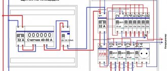
We decided to simplify the information about the division of the pen conductor and therefore all information will be provided with pictures. As an example, we will consider the power supply of a residential building.
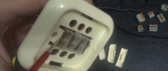
From the point where the PEN conductor is divided into zero working N and zero protective PE, their further combination is prohibited. At the point where they are separated, two clamps must be installed, which must be marked:
- The PE bus may also have the second name GZSh.
- Tire N.
For the jumper, you can use any wire that has the same cross-section. Sometimes you can install two jumpers. The busbar or clamp must have separate connection points. It is prohibited to connect them in one place.
The N bus must be installed on special insulators, and the PE bus can be fixed directly to the housing.
This paragraph states that natural ground electrodes can be used as re-grounding. If the resistance of the grounding devices meets the requirements of the PUE, then the PE bus can be connected using a conductor. From this point of the electrical installation, the input PEN conductor is divided into zero working N and zero protective PE conductors.
Safety requirements
For this reason, modern buildings use five wires (3 phases, PEN and PE), which start from busbars located in the basement. They are laid further up to the last floor. In contrast to this scheme, in old buildings the PE branched only in the floor electrical panel in houses with electric stoves.
- It is prohibited to use any pipes laid indoors as a PE conductor.
- If there are several grounding devices in the room, their potentials must be combined by an additional wire.
An example of modern installation of protective conductors PE conductor is used where it is impossible to obtain properly grounded grounding. This is typical for all multi-storey buildings. Therefore, the safety of people in these buildings directly depends on the correct connection of the PE wire. All information on how to properly manufacture a PE conductor is presented in section 1.7* of the PUE.
Grounding systems
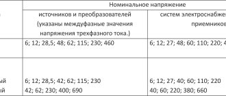
The basis for the design of safety systems against electric shock is the connection diagram of the windings of an electrical machine at a power plant or substation. Despite the fact that the source of electricity is an electric generator, it is separated from consumers by an entire power transmission system. It consists of a transformer, conductors and additional equipment. But since the electric generator is three-phase, the entire subsequent electrical power transmission network is also three-phase. But its configuration is determined by the windings of the transformers.
For optimal use of the power of each phase, including the possibility of building single-phase power networks, the transformer windings are connected in a star. From the point where all three windings connect, a conductor called the neutral emanates. There are electrical networks in which it is connected to a grounding device. In this case, a solidly grounded neutral is obtained. There are also networks that do not have a special connection to a grounding device. In this case, an isolated neutral is obtained.
But its isolation is conditional. There is a capacitance of conductors relative to the ground, as well as an equivalent resistance relative to the ground of other elements of the electrical network. Therefore, an isolated neutral is characterized by resistance relative to ground of one or another value. When electrical equipment is connected to an electrical network with a voltage of up to 1000 V with one of two types of neutral, additional protective conductors are used:
- PE (from the English words Protective Earth),
- grounding,
- potential equalization.
Working conductors are also used, designed to pass load currents between consumers and the neutral:
- zero neutral (N),
- combined zero protective working (PEN).
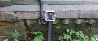
This is what a grounding device looks like. The combination of yellow and green insulation colors is required only for PE wire and other protective wires
Requirements for wiring colors during installation
A copper wire with one or two cores is pulled from the distribution box to the switch. The number of cores depends on the number of keys on the device. The phase should be broken, not the zero. During operation, it is allowed to use a white conductor for power supply, making a mark on the diagram.
The socket is connected taking into account the polarity. The working zero will be on the left, the phase will be on the right side. Grounding is located in the middle of the device and is clamped with a terminal.
If you have two cables of the same color, you can find the phase and neutral using a tester, an indicator screwdriver, or a multimeter.
On the electrical diagram it is worth indicating what L and N mean, but there are several of them used in electrical engineering. The single-line display shows the power part - type of power supply, number of phases per consumer. Here it is advisable to draw one notch on a single-phase network, three on a three-phase network and indicate the wires in color. Switching and protective equipment is marked with special symbols.
Reliable grounding of the PE conductor to the ASU
To install a grounding loop, you need three rolled steel pins with a diameter of at least 16 mm and a length of 3 m. They are driven into the corners of an equilateral triangle into a pre-dug trench 30-50 cm deep. The sides of the triangle should be 2.5 - 3 m. The upper ends of the pins are welded between a steel strip measuring 4x30 mm.
Ground loop
Instead of rolled steel, it is allowed to use a pipe with a diameter of at least an inch and a quarter with a wall thickness of 3.5 mm or a steel angle of 50x50 mm. To make driving easier, the ends of the pins need to be sharpened with a handy tool.
The welding points and the connecting bus must be well painted to protect against corrosion. Important! Grounding pins must not be painted!
A steel or copper conductor is laid from the circuit to the PE bus. The cross-section of the steel conductor must be at least 100 mm2, and the copper conductor must correspond to the cross-section of the PE conductor or more. After installing the grounding loop by the energy supply organization, it is necessary to measure the spreading resistance of the grounding loop. It should be no more than 10 Ohms when powered by three-phase current with a linear voltage of 380 V (phase voltage - (220 V).
Why divide PEN into two parts?
Proper division
It makes sense to divide the PEN wire into PE and N cores only if each of them is intended to be used for its intended purpose. This can be done in the following cases:
- in a private (country) house, when a tap from the PE bus is made in the distribution board, used to organize local re-grounding;
- in a city apartment building, where the residents of the entrance agreed to install a common grounding loop on the street next to the entrance;
- a copper descent is carried out from the PE wire to a homemade ground loop.
When in city houses a jumper is placed between the buses in the driveway panel, there is no need to talk about full grounding. The regulatory documentation on this matter provides a recommendation without a detailed explanation of the effect of such “grounding”.
Implementation of separation
Taking into account the presence of a separation point at the output of two different conductors, the procedure itself is performed using two separate buses. One of them is intended for connecting working conductors, the second serves protective ones. The tires must be connected to each other with a jumper. The functions of the jumper can be assigned to any wire or rigid bus, the material and cross-section of which coincide with the main ones.
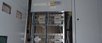
It is practiced to install the N bus on insulators, while the PE bus is mounted directly on the ASU body. An example of tire installation is shown in Figure 2.
Figure 2. Example of installation of N and PN buses in the ASU housing. Photo taken as an illustration from the site rx-it.ru
Tires must be provided with appropriate markings.
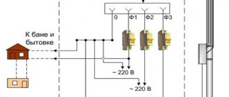
Wires or jumpers to the busbars serving the working and protective conductors are supplied from a special splitting busbar, which is designed to connect a PEN conductor., Figure 3. If this part of the wiring does not contain a circuit breaker, the splitter busbar is not used, which can significantly increase operational reliability wiring by reducing the number of bolted connections in its composition.
Figure 3. Transition implementation using three buses
For reasons of ease of use, it is permissible to install several N-type protective jumpers.
In the area of the transition, it is advisable to ground the PE and PEN wires again. For this purpose, specially organized grounding circuits or natural grounding conductors are used. This feature is specified in the PUE in paragraph 1.7.61
. The grounding parameters of this type are not specified by current regulations, but, based on common sense and taking into account the functions performed, it makes direct sense to ensure minimal resistance. You can use 4 ohms as a guide.
Why you can’t separate the PEN conductor in the floor panel
This option cannot be used for a number of reasons:
If we take into account exclusively the provisions of the PUE, they state that the separation of wires should occur at the input circuit breaker of an apartment building or a private detached house. Even if the apartment panel is considered a water machine (which is quite problematic to do), such a connection will be incorrect according to another requirement, namely, the PE conductor must be re-grounded, which is impossible to achieve in the floor panel. Even if you get clever and connect the grounding to the floor panel, there is another obstacle that threatens with large fines. The fact is that the electrical circuit during the construction of a house is approved by several authorities and its unauthorized change is a flagrant violation of all existing rules - in fact, it is a change in the design according to which the house was connected to the network
Such matters should be handled exclusively by the organization serving this house or area.
Of course, if such an organization plans any work to separate the Pen conductor, then there is no point in messing around with each floor panel separately. The best option would be to separate it at the input machine, which is what will be done.
An additional argument in favor of separating the Pen conductor on one circuit breaker in a residential building is the requirement of the PUE (clause 7.1.87) to install a potential equalization system in this place.
It is prohibited to do it in any other place, which means that the separation of the PEN conductor in the floor panel will in any case be done without observing all the necessary rules and precautions. As a result, the only correct method for grounding a house is a collective appeal to the organization serving the house or area
As a result, the only correct method for grounding a house is a collective appeal to the organization serving the house or area.
Conversion of the old TN-C power system to match the TN-CS system
The PE conductor is additionally connected to the grounding device of the house (re-grounding is performed).
In order to transfer the power system to a more advanced TN-CS, the PEN conductor is divided into PE - protective and N - neutral. By its principle, the TN-CS system is that the PEN conductor approaching the house at the input distribution device (IDU) is divided into two separate ones and in this form approaches the end consumer.
Socket with grounding contacts
The design of the sockets is such that when turned on, the grounding terminals are closed first, and only then the terminals with phase and neutral conductors. Neutral (neutral conductor is used to transmit electrical energy to the consumer, and protective to ensure safety.
Designation of phase and zero in electrical engineering
During the process of self-installation and connection of electrical equipment (this could be various lamps, ventilation, electric stoves, etc.), you will notice that the switching terminals are marked with the letters L, N, PE. The markings L and N are of particular importance here. In addition to marking the wires in electrics by letter, they are placed in insulation of different colors.
This greatly simplifies the procedure for determining where the phase, ground or neutral wire is located. In order for the installed device to operate in normal mode, each of these wires must be connected to the appropriate terminal.
Conductor splitting options
Input distribution device
In the distribution board, where the PEN conductor is separated, grounding is organized using the splitting method, but a jumper must be installed between N and PE
It is important that the earth bus is connected first, and only after that the connection of the working core is completed. In this situation, there are four possible options for connecting the PE wire:
- There is no jumper between it and conductor N - the working zero contact and the grounding bus are not electrically connected. An RCD is also not installed in the protective circuit.
- There is a jumper between these terminals, but the RCD is not installed.
- PE for grounding and N are short-circuited and an RCD is installed.
- There is no jumper, but there is an RCD.
- The emergency phase hits the device body.
- Then it goes to the ground bus.
- Further along it goes to the circuit of the transformer substation.
When considering the problem, it is important to take into account the resistance of the grounding circuit, which usually does not exceed 20 Ohms, taking into account the cross-section of the PE conductor in mm. square
In the event of an accident, the short-circuit current will not be enough to turn off the input circuit breaker. The protective circuit will function until the damaged area on the receiving side burns out completely. This situation will not cause any significant harm to a person, but the equipment will suffer serious damage (the worst case scenario is that it catches fire and ignites).
There is a jumper, but there is no RCD
PEN conductor separation diagram for single-phase network
In this case, the length of the supply line plays an important role (removal of the place of its damage from the input and distribution electrical panel), which determines the resistance of the wire for charge drainage. In the event of an emergency phase short circuit to the frame of damaged equipment, the leakage current first flows to the grounding bus. Then it has only two ways: part of the emergency electricity goes into the ground, and the other along the zero bus will trigger the machine at the input. In the situation considered, the jumper is used in case the AV does not work for some reason. But since the latter is practically impossible, it makes no difference whether it is present or absent.
There is a jumper and an RCD is installed
Since all protective and working conductors have a certain resistance, in this case the RCD should operate normally. When a short circuit occurs on the housing, the leakage current first flows to the RCD itself and only then goes to the input of the residential building. Here, as in the previous case, it is divided into two parts: some part of the whole goes into the ground, and part returns through the jumper to the panel, turning off the input machine. However, as a rule, things don’t come to this, since the RCD is triggered much faster.
In this situation, the jumper does not have much significance and is only a safety net, just in case: if suddenly, by a strange coincidence, the RCD does not work.
There is no jumper and an RCD is installed
This circuit will work in the same way as if there was a jumper. The only difference from the previous case is the lack of insurance if the RCD fails, which is unlikely. If this does happen, the circuit will begin to work according to the first of the considered options. In this case, the input device does not operate until the short circuit to the housing is transformed into a phase short circuit.
Letter marking of wires
For household and industrial power lines, insulated wires with internal conductors are used. Products differ depending on the color of the insulating coating and markings. The designation of phase and zero in electrics speeds up repair and installation work.
Marking of cables in electrical installations under voltage up to 1000 V is regulated by GOST R 50462-2009:
- in clause 6. 2.1 it is indicated that the neutral conductor is marked as N;
- clause 6.2.2. states that the protection wire with grounding is designated PE;
- in paragraph 6.2.12 it is said that in electrics L is a phase.
Understanding the markings simplifies installation work in commercial, residential and administrative buildings.
L – phase designation
In an AC network, there is a live phase wire. Translated from English, the word Line means an active conductor, line, and is therefore marked with the letter L. Phase conductors must be covered with colored insulation, since, being exposed, they can cause burns, human injuries, fire or failure of various equipment.
N – alphabetic symbol of zero
The sign of a neutral or neutral working cable is N, from the abbreviation of the terms neutral or NULL. When drawing up a diagram, the zero switching terminals in a single-phase or three-phase network are marked this way.
The word “zero” is used only in the CIS countries; throughout the world the core is called neutral.
PE – grounding index
If the wiring is grounded, the letter marker PE is used. In English, the meaning of Protective Earthing is translated as grounding wire. Clamps and contacts for switching with ground zero will be designated similarly.
Classification of zero buses
According to the functions performed, the zero buses included in the power supply system are divided into the following types:
- N – functional or working “zero”, which is a conductor for load currents.
- PE is a specially laid protective “zero” that provides the ability to organize grounding at the receiving end in a convenient place.
- PEN is a conductor that combines the functions of both of these buses.
Each of the conductors in the diagrams is highlighted in a certain color (N - blue, PE - yellow-green, and PEN - a combination of these). They must be selected according to their cross-section, which should not be less than the same indicator for phase buses.
This decoding also makes it possible to understand why it is necessary to separate the PEN conductor, what it serves, and how grounding can be arranged on the consumer side.
Features of performing separation
The separation of the combined protective conductor PEN into zero N and protective PE is carried out at the input of the electrical installation. In this case, the PE protective conductor is sometimes called the main ground bus.
In relation to individual residential buildings, the input panel is naturally chosen as the separation point; for households in apartment buildings, it is advisable to carry out this procedure at the ASU.
The separation can be performed in both single-phase and three-phase networks. There is no fundamental difference between them except for the number of phase wires.
To avoid unnecessary losses of electricity, it is advisable to perform the separation before the meter.
Phase designation (L)
The AC network includes live wires. Their correct name is “phase”. This word has English roots, and is translated as “line” or “active wire”. Phase conductors pose a particular danger to human health and property. For safe operation they are covered with reliable insulation.
The use of exposed live wires is fraught with the following consequences:
- 1. Electric shock to people. This can result in burns, injuries and even death.
- 2. The occurrence of fires.
- 3. Damage to equipment.
When designating wires in electrics, phase conductors are marked with the letter “L”. This is an abbreviation of the English term “Line”, or “line” (another name for phase wires).
There are other versions of the origin of this marking. Some experts believe that the prototype was the words “Lead” (lead wire) and Live (indication of voltage). Similar markings are also used to indicate the clamps and terminals to which the linear wires must be connected. For example, in three-phase networks, each line is also marked with a corresponding number (L1, L2 and L3).
Current domestic standards governing the designation of phase and zero in electrical engineering (GOST R 50462-2009) require linear conductors to be placed in brown or black insulation. Although in practice, phase wires can be white, pink, gray, etc. In this case, it all depends on the manufacturer and the insulating material.