Question 1
Why are 4-pole and 2-pole circuit breakers needed?
Answer A
In electrical panels where the protective zero and the working zero are separated, as a rule, four-pole circuit breakers are used to protect a three-phase load, and two-pole circuit breakers are used to protect a single-phase load. The protective zero is designed in the form of a continuous bus, which is not interrupted anywhere, and the machines open one or three phases and the working zero.
Answer B
In all cases when some kind of work or maintenance is required in the line after these machines. All repair and maintenance work on electrical circuit elements must be carried out with the mains completely disconnected. Those. theoretically, it will be enough at the input of the installation (building, house), but if there is a strong branching to independent consumers (in a house these are apartments, in a factory - workshops), then it is advisable to install it on each line. But indoors, you can already install single-pole ones to control specific lines.
Answer B
Since damage and aging of insulation is possible in both phase and neutral working conductors, and the RCD responds to leakage to ground from any of them, two- and four-pole switches should be installed on outgoing lines. Only in this case is it possible to find a faulty circuit by alternately switching on the lines, including a circuit with a leak of the neutral conductor without dismantling the input distribution device, and it is also possible to disconnect the faulty circuit to ensure the operation of the rest of the electrical installation. Note: in this answer, obviously, the emphasis is on the possible installation of a machine + RCD in these circuits.
Answer B1
If at the head of a group of several circuit breakers there is an RCD, in the event of its (RCD) tripping, it is much easier to look for damage with a two-pole circuit breaker or circuit breaker (P + N). And it’s easier to wait for an electrician to be called, because... you can turn off the AV of the damaged line. In the case of single-pole circuit breakers, the entire group under the protection of the RCD is de-energized. At the same time, I note that clause 3.1.17 has nothing to do with the topic of conversation, because it refers to a fuse. It is clear that the fuse installed in N, when tripped first, will leave a phase on the damaged consumer.
The use of a two-pole AB or AB (P + N) fits well into the third paragraph of clause 3.1.18 of the “PUE”: “Releasers in the neutral conductors are allowed to be installed only on the condition that when they are triggered, all energized conductors are simultaneously disconnected from the network "
Well, if you bring it under an explosive zone: 7.3.99 “PUE”: “In explosive zones of class B-I in two-wire lines with a neutral working conductor, the phase and neutral working conductors must be protected from short-circuit currents. To simultaneously disconnect the phase and neutral working conductors, double-pole switches must be used.”
Answer D
In explosive zones of class B-I in two-wire lines with a neutral working conductor, the phase and neutral working conductors must be protected from short-circuit currents. To simultaneously disconnect the phase and neutral working conductors, two-pole switches must be used (“PUE”, 7th edition, chapter 7, clause 7.3.99).
Reference. In explosive zones of class B-I in two-wire lines with a neutral working conductor, the phase and neutral working conductors must be protected from short-circuit currents. To simultaneously disconnect the phase and neutral working conductors, two-pole switches must be used (“PUE”, 6th ed., Chapter 7.3, clause 7.3.99).
Electric machines. Types and work. Characteristics
From the very beginning of the emergence of electricity, engineers began to think about the safety of electrical networks and devices from current overloads.
As a result, many different devices have been designed that are distinguished by reliable and high-quality protection. One of the latest developments is electric automatic machines. This device is called automatic because it is equipped with a function to turn off the power in automatic mode in the event of short circuits or overloads. Conventional fuses must be replaced with new ones after tripping, and the circuit breakers can be turned on again after eliminating the causes of the accident.
Such a protective device is necessary in any electrical network circuit. A circuit breaker will protect a building or premises from various emergency situations:
- Fires.
- Electric shocks to a person.
- Electrical wiring faults.
Types and design features
It is necessary to know information about the existing types of circuit breakers in order to correctly select the appropriate device during purchase. There is a classification of electric machines according to several parameters.
Breaking capacity
This property determines the short circuit current at which the machine will open the circuit, thereby turning off the network and devices that were connected to the network. Based on this property, machines are divided into:
- 4500 ampere circuit breakers are used to prevent faults in the power lines of older residential buildings.
- At 6000 amperes, they are used to prevent accidents during short circuits in the network of houses in new buildings.
- At 10,000 amperes, used in industry to protect electrical installations. A current of this magnitude can occur in the immediate vicinity of a substation.
The circuit breaker trips when a short circuit occurs, accompanied by the occurrence of a certain amount of current.
The machine protects electrical wiring from damage to insulation by high current.
Number of poles
This property tells us about the largest number of wires that can be connected to the machine to provide protection. In the event of an accident, the voltage at these poles is switched off.
Features of machines with one pole
Such electrical circuit breakers are the simplest in design and serve to protect individual sections of the network. Two wires can be connected to such a circuit breaker: input and output.
The purpose of such devices is to protect electrical wiring from overloads and short circuits of wires. The neutral wire is connected to the neutral bus, bypassing the machine. Grounding is connected separately.
Electrical machines with one pole are not input, since when it is disconnected, the phase is broken, and the neutral wire still remains connected to the power supply. This does not provide 100% protection.
Properties of machines with two poles
In cases where an emergency requires complete disconnection from the electrical network, circuit breakers with two poles are used. They are used as introductory ones. In emergency situations or in the event of a short circuit, all electrical wiring is switched off at the same time. This makes it possible to carry out repair and maintenance work, as well as work on connecting equipment, since complete safety is guaranteed.
Two-pole electrical circuit breakers are used when it is necessary to have a separate switch for a device operating on a 220-volt network.
A machine with two poles is connected to the device using four wires. Of these, two come from the power supply, and the other two come from it.
Three-pole electrical circuit breakers
In an electrical network with three phases, 3-pole circuit breakers are used. The grounding is left unprotected, and the phase conductors are connected to the poles.
The three-pole circuit breaker serves as an input device for any three-phase load consumers. Most often, this version of the machine is used in industrial conditions to power electric motors.
You can connect 6 conductors to the machine, three of which are phases of the electrical network, and the other three coming from the machine and provided with protection.
Using a four-pole circuit breaker
To provide protection for a three-phase network with a four-wire system of conductors (for example, an electric motor connected in a star circuit), a 4-pole circuit breaker is used. It plays the role of an input device for a four-wire network.
It is possible to connect eight conductors to the device. On the one hand - three phases and zero, on the other hand - the output of three phases with zero.
Time-current characteristic
When devices consuming electricity and the electrical network are operating normally, current flows normally. This phenomenon also applies to electric machines. But, if the current increases for various reasons above the rated value, the circuit breaker is triggered and the circuit is broken.
Question 2
Why in Russia, unlike European countries, in TN-CS and TN-S systems it is not prescribed to use circuit breakers with the number of poles 4P (for three-phase networks) and 2P or 1P+N (for single-phase networks). Perhaps there is some political or economic background to this moment? After all, it is quite obvious that by breaking the active neutral, we increase safety and simplify the diagnostics of the electrical installation!
Answer
Viktor Shatrov, assistant at Rostechnadzor (Electrotechnics News website, https://www.news.elteh.ru/aq/?&p=3 5)
The Electrical Installation Rules do not prohibit the use of 4-pole switches in three-phase circuits and 2-pole switches in single-phase circuits to disconnect the neutral working conductor simultaneously with the phase ones. The need to install protection against short circuits in the zero working (neutral) conductor with mandatory disconnection of the neutral conductor and the effect on the simultaneous disconnection of phase conductors is provided for in clause 473.3.2.1 of GOST R 50571.9 for cases where the cross-section of the neutral conductor is less than the cross-section of the phase conductors. At the same time, conditions are specified under which detection of a short circuit current in the neutral conductor is not required. Chapter 3.1 “PUE” stipulates that releases can be installed in neutral conductors only on the condition that when they are triggered, all live conductors of the circuit are switched off. The installation of protective switching devices in the PEN conductor circuit is not allowed, except for the cases provided for in clause 1.7.145 and clause 1.7.168 of the PUE, 7th edition.
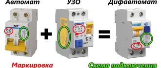
The difavtomat “DS 941” (1P+N) at overcurrent (not to be confused with leakage current) is triggered only in phase. It does not control overcurrent in the neutral.
The difavtomat “DS 652” (2P) at overcurrent is triggered in both phase and neutral. Therefore, it will tear both phase and neutral, regardless of where the overcurrent was.
Terms of Use
The power safety circuit breaker is produced in 5 climatic categories and is designed for operation under the following conditions:
- installation at altitudes up to 1000 m above sea level;
- outside air temperature from -40 to +40 degrees excluding frost and dew;
- relative air humidity 90% (+20 degrees) and 50% (+40 degrees);
- rooms without dust, aggressive concentrations of vapors and gases, there is no explosive atmosphere or dust outside;
- installation on a surface where drops of water, oil, and radiation particles cannot reach.
The dependence of the operational parameters of switches on environmental conditions is specified in GOST 17516.1-90.
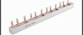
Any amperage from 10A to 100A. Four-pole repackaged (converted) circuit breaker based on switch..
Four pole circuit breaker
On the territory of the Russian Federation, three-phase power supply systems are mainly used, and accordingly, the protection devices used in them are also three-phase. However, electrical equipment manufacturers also produce four-pole circuit breakers. Let's try to figure out in what cases the use of four-pole machines is justified, and when it is possible to get by with installing a three-pole device. Laying a cable to connect a high-power consumer is always associated with high financial costs. If the cable length is significant, sometimes it is economically justified to use a cable with a cross-section of the neutral conductor smaller than the cross-section of the phase conductors. An example would be cables VVGng 4*35+1*16 and VVGng 5*35, the difference in cost can reach 60%. By using a cable with a truncated cross-section of the neutral conductor, you can obtain noticeable economic benefits over a long laying length. In this case, according to GOST R 50571.9 “Electrical installations of buildings”, the use of a four-pole circuit breaker is prescribed for protection against short circuits.
Question 3
What is the difference between “1P+N” and “2P” differential circuit breakers?
Answer
The differential circuit breaker has 3 functions:
- a) overload protection;
- b) short circuit current protection;
- c) leakage protection.
- a) thermal release;
- b) electromagnetic release;
- c) RCD.
Further: “1P+N” means that the thermal and electromagnetic releases are only in the phase circuit. The zero only opens, i.e. the neutral conductor circuit does not contain the specified protections.
“2P” - accordingly, contains a bimetallic plate and an electromagnetic release coil both in the phase conductor circuit and in the neutral conductor circuit.
Question 4
Please provide a link to the document regulating the installation or absence of a switching device in the neutral working conductor for a system with a solidly grounded neutral. There is no clear indication in the PUE. Such requirements are established in foreign documentation.
Answer
Lyudmila Kazantseva, chief specialist of the Research Center “NIIProektelectromontazh” (ANO)
Clause 461.2 GOST R 50571.7-94 “Electrical installations of buildings. Part 4. Security requirements. Separation, disconnection, control" contains the instruction: "In the TN-S system, it is not necessary to separate or disconnect the working neutral conductor." “Not required” means not necessary, but possible.
In accordance with clause 1.7.8 “PUE”, the neutral working conductor is a current-carrying part. Since when the phase conductors are disconnected, as a rule, the neutral working conductor is also de-energized, the regulatory and technical documents do not require its mandatory disconnection. Typically, the need to install a switching device in the neutral working conductor is determined by operating conditions. For example, the same GOST R 50571.7-94 (clause 464.2) in places where there is a danger of electric shock requires that all current-carrying conductors, including the neutral working conductor, be disconnected with emergency shutdown devices; Clause 7.1.21 “PUE” requires that the neutral working conductor also be disconnected simultaneously with the phase conductor when supplying single-phase consumers from a multiphase supply network with branches from the overhead line. An example of a switching device that also disconnects the neutral working conductor is plug sockets. For all mobile and mobile installations, as a rule, it is necessary to disconnect the neutral working conductor simultaneously with the phase conductors of the supply cable with one common switching device.
Question 5
GOST R 50571.7-94 clause 465.1.5 states that control devices that switch power from one power source to another must act on all live conductors. At the same time, the possibility of switching on sources for parallel operation should be excluded if the installation is not specifically designed for such an operating mode. In this case, you should not disconnect the neutral working conductor combined with the protective conductor, or the protective conductor in a four-wire system. Does this mean that in the TN-S power system in the ATS box the starter must disconnect the phase and neutral working conductors?
Answer
Alexander Shalygin, Valery Shein, JSC "Roselektromontazh"
In a TN system, it is not allowed to disconnect the PEN conductor or PE conductor. As for the N-conductor, disconnecting it, as a rule, is not required. Disabling the N conductor in the TN-S system is required:
- firstly, if its cross-section is smaller than the cross-section of the phase conductors, and the protection of phase conductors from overcurrents does not simultaneously protect the N-conductor;
- secondly, if differential protection is installed at the input from the ATS. The continuity of the N-conductor in this case leads to the redistribution of zero-sequence currents from different sources and, as a consequence, uncertainty in the operation of differential protection.
Disconnection of the N conductor is also required for a number of special installations in order to increase the level of safety. For example, in accordance with the requirements of Chapter 7.1 of the PUE, in single-phase networks it is necessary to install two-pole switches. In single-phase unphased group networks (socket networks) when using phased electrical appliances of protection class I, a number of standards also require two-pole switching. When switching to a backup source (DES) when using a four-wire network, this measure is meaningless, since a jumper is installed between the PE and N buses of the input device. If it is necessary to completely separate the diesel power plant, the line from the source should be made five-wire.
When assembling a distribution panel for a three-phase network, 3-pole circuit breakers are used. If a network overload occurs or a short circuit occurs, such a machine will disconnect three phases at once.
Main characteristics
One of the main characteristics of the input circuit breaker is the so-called “ultimate switching resistance” (UCR), which is usually defined as the maximum breaking and closing capabilities. Each of them is represented as the largest value of current in the switched circuit, which the given device is capable of opening (closing) while simultaneously extinguishing the resulting electric arc.
Note! On the other hand, this ability refers to the maximum value of the short-circuit current at which the machine switches off several times, while remaining fully operational.
This performance indicator is usually indicated on the front panel of the device body in a place convenient for its fixation.
In addition to current parameters, input devices are characterized by the supply voltage with which they are designed for long-term operation. A typical apartment VA is intended for switching standard 220 Volts and has no more than 2 switching groups. And in power supply circuits laid directly from a local substation or overhead line, three-phase devices designed for a voltage of 380 Volts can be installed.
When considering various designs of water machines, differing in the number of simultaneously switchable groups of contactors, the following varieties can be distinguished:
- Single-pole switching devices;
- Double-pole circuit breakers;
- Multi-pole (three- and 4-pole) switches.
Four-pole input circuit breaker
The first two positions are used to input single-phase voltages, and multi-pole - for switching 380 Volt power circuits (it most often provides 3 or 4 switching groups).
Additional Information. According to the requirements of the PUE, in a single-phase network for the input of three-wire lines with a separate grounding wire, it is not allowed to use several single-pole switches (this also applies to three-phase networks of 4 wires).
When choosing an input circuit breaker, you usually install at least a two-terminal network, through which, if it is necessary to repair the electrical network, you can de-energize the apartment not only in phase, but also through the neutral wire (the neutral wire can be bypassed to the meter).
In situations where only 2 wires (without a neutral) are inserted into the house, it is allowed to install a single-pole circuit breaker. In cases where a grounding conductor is artificially added to them (by arranging repeated grounding, for example), it is necessary to use a two-pole device.
Let us consider in more detail how single- and multi-pole circuit breakers approved for use are connected.
How many poles are there?
Single-pole, two-pole, three-pole and four-pole circuit breakers
In the distribution panel of an apartment or house, single-pole circuit breakers are most often used. Their task is to disconnect the phase conductor, thereby interrupting the supply of electricity to the circuit. Differential circuit breakers and RCDs disconnect both the phase and the working zero at the same time, because their operation may be due to a violation of the integrity of the wiring. The input circuit breaker in such a panel should always be two-pole.
Three-phase current is used by enterprises to power powerful units that require a voltage of 380 volts. Sometimes a four-core cable (three phases and a working zero) is supplied to a residential building or office. Due to the fact that equipment designed for such voltage is not used in these rooms, the three phases are separated in the distribution panel and a voltage of 220 is obtained between each phase and the working zero.
For such panels, 3-pole and four-pole circuit breakers are used. They are triggered when the rated load on any of the three wires is exceeded and turn them off all at the same time, and in the case of a four-pole wire, the working zero is additionally turned off.
Why use two and four poles
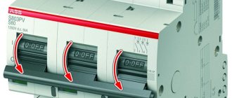
The input circuit breaker must completely disconnect all phases and the working zero, because One of the wires of the input cable may leak to zero and if it is not disconnected using a single-pole or 3-pole circuit breaker, there is a possibility of electric shock.
Leakage at 3-pole circuit breaker
The figure shows that in this case the entire working zero in the network is energized. If you use an input circuit breaker that disconnects phase and zero, this can be avoided; therefore, the use of four-pole and two-pole circuit breakers for three-phase and single-phase electrical networks is safer.
Price
3-pole circuit breakers, depending on the manufacturer, also differ in price. In the table below you can compare the cost of such electrical installation products from the most popular brands in the Russian Federation: IEK, Legrand, Schnider Electric and ABB:
Cost table for 3-pole circuit breakers leading on the Russian market
Video about switch polarity and connection methods
The video will be useful for beginners who want to understand the differences and functionality of single-pole, double-pole, 3-pole and 4-pole circuit breakers. How to connect them correctly and in what cases one or another machine should be used.
Three-pole and four-pole VA
Differential automatic machine reliable protection of electrical circuits and people
Devices of this type are installed in 380 Volt power supply networks and allow you to simultaneously switch all phases at once. Their design may include special arc-extinguishing chambers that provide switching of large loads (significant currents). The figure below shows the appearance and schematic diagram of this device.
Three-pole input machine
When depicting it graphically, the rules for designation and marking of supply wires, regulated by current standards, are used, consisting of the following:
- According to these regulations, the phase conductors are designated as A, B and C, and also differ in color by the sheath (insulation) protection;
- The set of colors can be arbitrary, but the most commonly used colors are red (brown), green and yellow;
- When such a machine is turned on at the entrance to a facility (in a private house or garage workshop, for example), the neutral wire in blue insulation is passed past it and connected directly to the corresponding terminal of the electric meter.
If it is necessary to switch all four wires of the 380 Volt supply cable, you will need to install a 4-pole circuit breaker used at the entrance to this facility. This VA connection option provides additional protection for the serviced network via the neutral wire.
A typical circuit breaker is usually designed for rated switched currents of the order of 63-100 Amperes (their exact value depends on the size of the load connected to a given network).
To correctly calculate this value, it is necessary to inspect all three-phase units available at the site (electric motors, pumps, etc.), taking into account the active and reactive power they consume. After this, it remains to determine the currents flowing through their circuits in extreme operating conditions, and then summarize the results.
In the final part of the review, we note that if the power consumed by this facility increases above the established norm (15 kW), special permission and additional payment will be required. After receiving it from the relevant authorities, it will be possible to install an introductory machine with the required denomination.
Comments:
And I thought that the three-pole one is connected as phase-zero-ground, but it turns out to be like this... Live and learn! Can it be used in a panel for a single-phase network, if three circuits need to be disconnected at once?
Evgen, why is it needed then? Power all three phases through a single-pole switch and they will turn off at the same time without any problems! And you'll save space on the rack.
Why can't you use a three-pole switch in a single-phase network? Disconnect phase, neutral and ground at the same time? If you place it, for example, at the input to the panel. It seems to me that this is more correct.
Denis, why do you need to disconnect the ground at the input? A three-pole switch is only
in a three-phase network, but using it in a single-phase network is possible, but impractical. Just as impractical as disconnecting the ground in the example you gave
Sometimes it’s useful to turn off the zero - when there is a phase imbalance, in villages all the time. But you need to tear up the ground ONLY if there is a split trans, and AFTER it.
Virtual Private Servers
One of the most prominent, in the literal sense of the word, characteristics of a circuit breaker is the characteristic that determines the number of poles of the circuit breaker.
and if you need to disconnect two phases and three-pole zero will work
Leave a comment Cancel reply
Fuel-free generator - a way to make money on illiteracy
Pros and cons of vertical wind generators, their types and features
Windmill for a private home - a toy or a real alternative
Power bank with solar battery - calculation for illiteracy
How to choose a solar panel - overview of important parameters
The purpose of circuit breakers introduced into electrical network circuits concerns protective functions. If you use a hand-held device during network overload, the likelihood of significant equipment damage increases significantly.
Automatic two-pole and three-pole switches reduce such risks to a minimum, as they provide instant circuit breakage in case of an accident.
We will understand the features of electric machines, and provide tips on choosing, installing and operating such devices.
Design of circuit breakers
In the practice of using such equipment, there is a frequent use of three types of devices: single-pole, two-pole, three-pole.
What is the difference between these three types of slot machines? Let's try to figure it out.
A single-pole device, in general, does not raise any special questions. If you implement a single-phase circuit breaker, the device will work like a regular switch, only in automatic response mode - that is, without user intervention, it will break the circuit in case of violation of the specified operating conditions.
Brief characteristics of a two-terminal network
A similar device, but designed in the form of a two-pole circuit breaker, is slightly different in functionality.
The circuitry of the two-pole device is made taking into account the control and comparison of the operating conditions of two independent current lines.
Two-pole circuit breakers are used, as a rule, for implementation in electrical network construction projects, when it is necessary to control and compare the operating conditions of two sections of a single electrical network. Essentially, the two-pole device configuration is a tandem of a pair of single-pole devices.
However, the two-terminal circuit protection and blocking circuit works on the principle of comparing the parameters of each device separately, in real time. If in any of the two control sections the parameters go beyond the settings, both lines are immediately broken.
This important point shows: replacing a two-pole machine with a pair of conventional single-pole devices is impossible in principle. In case of overload of one of the circuits (or short circuit), only one circuit breaker will operate.
But given that the electrical network is unified, electricity will continue to flow through the second device powering another section. Such a situation leads to dire consequences.
Meanwhile, there are two subtypes of two-pole devices:
- with single pole protection and normal neutral switching;
- with protection of both poles and their simultaneous switching.
The former are usually used as input machines, thanks to which phase and neutral conductors are switched. Moreover, this connection scheme involves the use of an additional PE line - a grounding wire.
The latter are used in circuits of one network, where two sections operating under conditions of different current loads are powered.
Features of the three-terminal device
The main purpose of a three-pole circuit breaker is to use three-phase networks in circuits. The design features of this type of device include the presence of protective functions on each individual pole.
Triggering of the protection on any of the poles leads to the opening of all poles.
Despite the specific purpose of machines of this type, it is quite acceptable to use them on single-phase or two-phase lines.
Structurally, a three-pole circuit breaker contains the following elements:
- control mechanism;
- contact system;
- arc extinguishing module;
- release device.
Free contacts are usually mounted inside the device cover. The contact system is connected to the traverse of the main contacts kinematically.
The functional components of the device are mounted inside the housing. The cover and body of the machine are made of materials that do not allow electric current to pass through (plastic, textolite, etc.).
Circuit breaker - purpose and characteristics
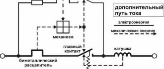
A circuit breaker is one type of automatic protective device . It is installed in electrical networks for manual switching on and off of current in a circuit under normal operating conditions, as well as for automatic shutdown when abnormal conditions occur. For correct and reliable operation, it is necessary to use the machine, taking into account its characteristics in accordance with its intended purpose.
What functions does a circuit breaker perform? Device types
The main task of a circuit breaker is to de-energize the protected electrical line when large currents occur in it. And they arise as a result of a short circuit or the connection of a load whose power is very high and does not correspond to the parameters of the network. Due to the high current, the conductors can heat up and the insulation can ignite. In this case, the electrical cable in a wooden house can cause a fire. Therefore, the circuit breaker must recognize in time a high current that can cause damage to the electrical network and turn off this network in time.
Legrand single-pole circuit breaker
Depending on the method of operation, devices can be divided into thermal and electromagnetic. In the first, the circuit opens from a change in the shape of the bimetallic plate, which heats up as the load increases. This type works quite slowly. Switches with an electromagnetic trip operate much faster. They respond well to short circuits in the circuit and can turn it off in hundredths of a second.
Based on their design, devices are divided into three types:
- air circuit breaker;
- molded case switch;
- modular switch.
The air circuit breaker is usually large in size. This type of device is enclosed in a metal housing and can protect circuits with currents up to 6300 A.
The switch in a molded case made of dielectric material is more compact and is designed to protect circuits in which currents up to 3200 A occur.
Three-pole circuit breaker IEK
Modular switches are small, made in a plastic case and are designed not only for automatic protection of circuits, but also for manual switching on and off. Such devices have a width that is a multiple of 17.5 mm and standardized mounting points on a 35 mm wide DIN rail. This type of switch is used to protect household electrical networks in private houses and apartments.
To protect a single-phase electrical network, a single-pole or two-pole circuit breaker is installed, and to protect a three-phase network, a three-pole or four-pole circuit breaker is installed.
For comprehensive protection against high currents and leakage currents in networks, differential circuit breakers are used. They combine a conventional machine and a residual current device .
Characteristics and parameters of the circuit breaker
Characteristics and parameters play an important role when choosing a device of this type for a particular electrical circuit.
Time-current characteristic
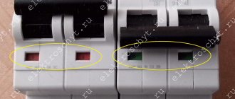
The main feature of the circuit breaker is the time-current characteristic (TCC). It indicates the value of the current that can occur in the circuit, at which the machine will turn it off without a time delay. This value is not absolute, but depends on the rated current, which is why it is indicated on the device next to it. Identified by the letter A, B, C, D, K or Z.
Each letter means how many times the instantaneous shutdown current should exceed the rated one:
- A – 1-3 times;
- B – 3-5 times;
- C – 5-10 times;
- D – 10-20 times;
- K – 8-14 times;
- Z – 2-4 times.
Therefore, two machines with the same rated current will operate differently. For example, the C16 circuit breaker will instantly turn off when a current of 80 A appears in the circuit, and the D 16 switch will instantly turn off only when a current of 160 A occurs.
Rated current
This parameter has already been mentioned above. The rated current is the one that the machine must pass under normal (standard) operating conditions. Exceeding this value in the circuit indicates the occurrence of an emergency situation. In this case the circuit must be disconnected.
But the shutdown will not occur immediately if the current does not exceed the value of the time-current characteristic. The tripping time will depend on the type and model of the release and how much the rating has been exceeded.
Ultimate breaking capacity
This parameter indicates the maximum current value in the network protected by the switch, at which it will turn it off while remaining operational. It is likely that when the current reaches a value greater than the maximum breaking capacity of the machine, the latter will instantly fail. In this case, the electromagnetic coils will most likely burn out, but the mechanical part will remain intact, continuing to pass a huge current. If the conductivity is insufficient, strong heating and fire may occur.
Current limiting category
The time it takes to turn off the circuit until the current stops depends on what category the circuit breaker belongs to.
short circuit will become maximum. There are three categories of current limiting:
- shutdown time 10 ms or more;
- shutdown occurs in the range from 6 to 10 ms;
- The line disconnection time will be no more than 6 ms.
Accordingly, the higher the category of the device, the more secure the network it protects. After all, with a quick disconnection, the conductors do not have time to heat up to the point where the insulation may catch fire.
Voltage
This parameter depends on the network in which the circuit breaker is used. Single-pole and two-pole devices are designed to operate in single-phase current networks and therefore the voltage is 230 V; for three-pole and four-pole machines the usual voltage is 400 V.
How to choose a circuit breaker
When choosing a circuit breaker to protect the electrical network in a private home, a modular circuit breaker will be the best. Their number must correspond to the number of protected circuits. As a rule, lighting circuits, socket circuits are separately protected (they are often divided into two groups, so that when the protection device is triggered, some of the sockets remain in working order), lines of high-power appliances (electric stove, electric oven, air conditioner, electric heating boiler).
To protect the networks of a small home, devices with VTC (time-current characteristic) - type C are perfect. There is no need to be afraid of a current of 80 A in a circuit designed for a load of 3.5 kW. The machine will have time to turn it off before the insulation has time to heat up even a little.
The rated current is selected by calculation. Firstly, it is necessary to determine the total load of all electrical consumers in Watts for the entire protected circuit. Secondly, divide the resulting value by the voltage in the network in Volts.
Of course, it is better to choose a device with higher current limits and categories.
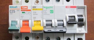
For reliable network protection, it is recommended to choose products from well-known brands - ABB, Le g rand, Siemens. Recently, IEK automatic machines have begun to please with their quality. However, products of these brands are much more expensive than, for example, DEKraft, Schneider Electric. It is advisable to install expensive devices at the inputs to an electrical installation, as well as to protect circuits in which devices that require reliable power operate - computers, office equipment, refrigeration equipment. For home lighting networks, as well as for outbuildings, you can install automatic machines from the budget line.
Installation details of switches
For all electrical devices of this design, the order of implementation into the electrical circuit is determined.
The established procedure, in particular, requires the following actions by installers before two-pole and three-pole switches are installed:
- the device must correspond to the design for the current circuit;
- the machine body is free from deformation and damage;
- The on/off lever works clearly in manual activation mode.
The base on which the device is supposed to be installed must be checked for evenness of the surface. Installation on bases where, due to the uneven surface after mounting, the machine body is subject to bending stresses is not allowed.
Connection to network conductors
The connection of copper conductors with a cross-section of 16 - 25 mm 2 is carried out through cable lugs ( GOST 9688-82) . If it is necessary to make a connection with copper conductors with a cross-section of 4 - 16 mm 2, cable lugs of a different type are used ( GOST 7386-80 ).
In relation to connections of aluminum wires, end elements similar to TAM-7 are used, corresponding to the parameters of GOST 9581-80 .
The network conductors supplying voltage from the power source are connected to the upper group of fixed contacts of the circuit breakers. It is necessary to supply and connect conductors so that they do not create forces on the terminals of the machine.
The tips should be tightened tightly with contact clamps, but without extreme force that could lead to thread failure. The termination of conductors in cable lugs should be given great care. Be sure to use insulating tubes and tape as a protective sheath.
Nuances of placement and fastening
When installing several pieces of equipment, it is necessary to follow the rules for arranging the devices relative to each other. Thus, the distance between closely located devices should be maintained at least 5 mm.
Minimum distances from metal parts of switchgears: from above 30 - 50 mm, from the side 5 - 10 mm, depending on the magnitude of the supplied voltage.
If the installation uses devices that are structurally made in an additional shell, all installation manipulations with them are carried out with the shell cover removed. The installation of the cover is carried out taking into account the correct insertion of the drive mechanism. The cover is fastened with screws evenly.
Upon completion of installation, the machines must be checked for clarity of the moment of switching on/off.
Wiring diagrams and rules for connecting the switch are described in detail in this article.
How to choose a circuit breaker
The machine protects the electrical network from high currents. In the event of an emergency, this device must turn off the power supply. But sometimes such an excess happens when the switch may not work. One of the reasons for this circumstance is the installation of an incorrectly selected machine. How to choose a circuit breaker?
To select a circuit breaker, you should pay attention to the technical characteristics of the protective device. Such characteristics include: rated current value, trip category, load power and many other parameters. In addition, the choice of device is influenced by the manufacturer of the electrical device, as well as the cost of the product.
Characteristics of the circuit breaker
The time-current characteristic has the following types:
- Type A. In this type, thermal protection is triggered when the ratio of the electric current in the circuit to the rated current exceeds 1.3. In this case, the protective device will operate after 60 minutes. If the current is exceeded, the response time will decrease. In addition, electromagnetic protection is activated, which provides for a twofold increase. In this case, the device will turn off after 0.05 seconds. This type of machine is installed in electrical networks prone to short-term overloads. This type of protective devices is not used in domestic conditions.
- Type B. In a type B protective device, the excess is allowed from 3 to 5 times. In this case, thermal protection will operate in 4–5 seconds, and electromagnetic protection – within 0.015 seconds. This type is used in lighting lines that are not subject to high inrush currents.
- Type C. A more popular type with a large permissible overload. In this case, the thermal protection will turn off the system when the load is five times higher and will operate after 1.5 seconds. The solenoid of such a machine can withstand overload ten times. This device is used in everyday life, as well as in electrical networks where there is moderate starting current and mixed load.
- Type D. These devices withstand ten times the thermal protection standard and twenty times the electromagnetic protection standard. The machines are installed in electrical networks with high starting current.
- Type K. The machine is installed in circuits with inductive loads and can withstand an overload of eight times. At the same time, for networks with constant voltage, an excess of eighteen times is possible. The time period varies from 0.02 – 1.05 seconds, depending on which protection is triggered.
There is a type Z circuit breaker that is used to connect electronic devices. The protective device can withstand an overload of 2–4 times. The shutdown time for thermal protection is 1.05 seconds, and for electromagnetic protection it is 0.02 seconds.
Criterias of choice
How to choose a circuit breaker? When considering various models of automatic devices, it is necessary to pay attention to more important indicators, such as: rated voltage, breaking capacity, number of poles, maximum operating current.
Electric automatic
The rated voltage depends on the voltage characteristic of this type of device. In addition, it must have a value the same or higher than the rated mains voltage.
The maximum operating current of the device is related to the load that will be connected to this network. To find out the load on the electrical network, you need to calculate the power of the existing electrical appliances that you plan to connect. So, with a total load of 1 kW in a 220 volt power supply, the maximum operating current will be 5A.
Wire insulation is of great importance. Read here about which insulation is better.
In an electrical network with a load of 1 kW, a voltage of 380 volts, the maximum operating current is 3A. In this case, the choice of machine must be chosen on machines whose rated current is equal to or higher than the maximum operating current.
Rated current
When choosing a device, it is necessary to take into account the rated shutdown current, which must exceed the value of the short circuit current. That is, the shutdown current is the maximum short circuit current. Manufacturers produce protective devices with rated currents of 4, 6, 10, 16, 25, 32, 40, 63, 100A, 160A.
Selectivity
This technology is based on the use of current-limiting protective devices. Such a system helps turn off one of the devices if an accident occurs. At the same time, the rest of the electrical network remains operational. Selectivity is achieved by implementing a time-current parameter.
Time selectivity provides a difference in response time. Thus, the machine closest to the consumer should have an operating time of 0.02 seconds, the next protective device should have a shutdown time of 0.5 seconds, and the last protective device should turn off after one second. At the same time, the third device insures the second, and the second – the first.
Current selectivity means that these circuit breakers must have a corresponding shutdown indicator based on the current value. The first should have a parameter of 200A, the second – 300A, and the third – 400A.
Maintenance during operation
Normal operating conditions of two-pole and three-pole circuit breakers make it possible to allocate time for technical inspection of devices no more than once during three years of operation. This fact once again confirms the high quality of execution of almost any machines.
Meanwhile, according to the instructions, a technical inspection must be performed if the circuit breaker has tripped due to a short circuit current.
For any reason, be it a device triggered in an emergency or scheduled maintenance, technical inspection of devices includes:
- diagnosing the on/off mechanism in manual mode without load;
- checking the tightening of the screws of the main and free contacts;
- reliability of fastening the device to the base;
- cleaning from dirt and foreign objects;
- simulating shutdown by mechanical impact on the sensitive element;
- performance check in operating mode.
The practice of using electrical networks marks the handling of devices from different manufacturers, including domestic and foreign.
The majority of all automatic protection devices in use are characterized by impeccable performance in terms of quality.