What is transformation ratio
The transformer does not change one parameter to another, but works with their values. However, it is called a converter. Depending on the connection of the primary winding to the power source, the purpose of the device changes.
These devices are widely used in everyday life. Their goal is to supply a home device with power that corresponds to the nominal value specified in the passport of this device. For example, the network voltage is 220 volts, the phone battery is charged from a 6 volt power source. Therefore, it is necessary to reduce the mains voltage by 220:6 = 36.7 times, this indicator is called the transformation ratio.
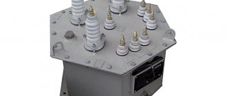
To accurately calculate this indicator, you need to remember the design of the transformer itself. Any such device has a core made of a special alloy and at least 2 coils:
- primary;
- secondary.
The primary coil is connected to the power source, the secondary coil is connected to the load, there can be 1 or more of them. A winding is a coil consisting of an electrical insulating wire wound on a frame, or without it. A complete turn of the wire is called a turn. The first and second coils are installed on the core, with its help energy is transferred between the windings.
Analysis of idle speed measurement results
During acceptance tests and overhauls, the data obtained is compared with the report of the corresponding tests carried out at the plant after the manufacture of the transformer. A discrepancy of more than 5% is not allowed.
For single-phase transformers in the same cases, the power loss should not differ from the original value by more than 10%.
In operation, only the no-load current is measured based on experience with the rated voltage or the power loss at a reduced one. PTEEP does not normalize deviations from the norm.
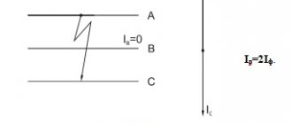
However, if damage is suspected in a transformer, the method of measuring losses using three consecutive tests gives a very valuable result. Since the windings of the transformer phases are in unequal conditions, it is possible not only to calculate whether there is a defect there, but also to determine the defective phase.
The path of the magnetic flux when exciting terminals AB and BC is the same. Therefore, the power losses for experiments at these phases will not differ. When the AC phases are excited, the path traveled by the magnetic flux is longer, so the power losses will be 25-50% higher than the previous ones. By comparing these indicators, it is possible to identify at which phase there is a defect.
Definition and formula of transformer transformation ratio
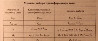
It turns out that the coefficient is a constant value showing the scaling of electrical parameters; it completely depends on the design features of the device. For different parameters, k is calculated differently. There are the following categories of transformers:
- by voltage;
- by current;
- by resistance.
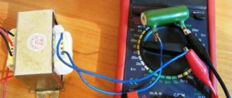
Before determining the coefficient, it is necessary to measure the voltage on the coils. GOST states that such a measurement must be made at idle. This is when there is no load connected to the converter, the readings can be displayed on the nameplate of that device.
Then the readings of the primary winding are divided by the readings of the secondary, this will be the coefficient. If there is information about the number of turns in each coil, the number of turns of the primary winding is divided by the number of turns of the secondary. In this calculation, the active resistance of the coils is neglected. If there are several secondary windings, find their own k for each.
Measuring the dielectric loss tangent in a transformer
These measurements are carried out for transformers:
- voltage 110 kV and above;
- with a capacity of 31,500 kVA or more.
The requirements for temperature and measurement circuits are the same as for insulation resistance measurements. Standards for values measured after overhaul are given in the table below.
There are no strict standards for tangent in operation, but an analysis of the dynamics of their change over time is required.
Particular attention should be paid to the measurement results if other indicators deteriorate.
Testing the resistance of transformer windings to direct current.
The R60 insulation resistance measurement method is the simplest and most accessible; it is widely used to monitor the insulation condition of transformers and is used: 1) to determine gross defects in transformers before turning them on, for example, local contamination, moisture or damage; 2) to assess the degree of insulation moisture in combination with other indicators in order to determine the possibility of putting the transformer into operation without additional drying. The method is based on the peculiarities of changes in the electric current passing through the insulation after applying a constant voltage to it. The insulation of the transformer windings is a non-uniform dielectric. When a constant voltage is applied to the terminals of the circuit, the flowing current will consist of the arithmetic sum of three components: 1) capacitive current Ig, due to the so-called geometric capacitance Cr. The current Ig almost instantly drops to 0, since the capacitance Cr is connected to the source without resistance and does not affect the measurement results of R15 and R60; 2) absorption current Iabs flowing through the Rabs-Sabs branch. This current reflects the process of charging the dielectric layers through the resistance of the previous layer. As the insulation is moistened, the resistance Rabs decreases, and the capacitance Sabs increases, therefore, for more moistened insulation, the current Iabs has a greater value and drops to 0 faster. For dry insulation, the resistance Rabs is high, the charge of the capacitor Sabs flows slowly, so the initial value of the current Iabs is small, and the current subsides for a long time; 3) through conduction current Iskv flowing through resistance Rskv, caused by both external contamination of the insulation and the presence of through leakage paths in it. This current is established almost instantly and does not change over time. The insulation resistance is inversely proportional to the sum of the indicated current components; at the beginning of the measurement it has the smallest value, and then as the current Iabs decreases, it increases, reaching a steady value determined by the current Irms. In order to have comparable results, the insulation resistance is measured 60 s after the voltage is applied, although in some cases the current Iabs has not yet completely decreased by this time. The insulation resistance value gives an indication of the average condition of the insulation and decreases as this condition deteriorates mainly due to moisture and contamination. 9. Transformer testing - Operation of power transformers. Testing of transformers after a major overhaul During operation, the most complete measurements and tests of a transformer are carried out after its overhaul in order to check the quality of the repair, as well as to check the characteristics of the transformer for compliance with the requirements of regulatory documents. The transformer testing program has the following content: 1. Determination of winding insulation characteristics. 2. Testing the insulation of windings with increased voltage. pp. 1 and 2 are discussed in more detail below. 3. Tests with increased voltage of insulation of magnetic circuit elements and secondary circuits of protective and measuring equipment. This insulation is tested against grounded parts of a transformer with a voltage of 1 kV for 1 minute. 4. Measurements of DC winding resistance. These measurements are carried out to identify defects in the solder joints of the windings and the contacts of the switching devices. Measurements are made on all branches of the on-load tap-changer. The resistances of different phases on the corresponding branches should differ from each other by no more than 2%. 5. After repairs associated with partial or complete replacement of windings, the transformation ratios are checked. The transformation coefficients of different phases on the corresponding branches should differ from each other or from the manufacturer’s data by no more than 2%. For transformers with on-load tap-changer, this difference should not exceed the value of the regulation stage. Measurements are carried out using the method of two voltmeters with an accuracy class of at least 0.5 when a voltage of 380/220 V is applied to the higher voltage winding and the low voltage winding is open. 6. After repairs associated with partial or complete replacement of windings, a group of winding connections is checked. Measurements are carried out using a direct current source (battery), connected alternately to terminals A-B, B-C and C-A of the primary winding. The plus of the source is supplied to the pin designated first. In each case, the reading of a magnetoelectric voltmeter (a voltmeter with zero in the middle of the scale) is monitored at terminals a-b, b-c and c-a of the secondary winding. The plus of the voltmeter is connected to the terminal designated first. Based on the totality of voltmeter readings, a group of windings is judged. In table Figure 5 shows the deflection signs of the voltmeter needle for various groups of transformer windings. Sign 0 corresponds to the absence of arrow deviation. Table 5| a-b b-c c-a | a-b | b-c | s-a | ||
| Winding group 12 (0) | Winding group | L1 | |||
| A-B | + | — | — | + | — |
| B-C | — | + | — | — | + |
| S-A | — | — | + | — | + |
7. Measurement of current and no-load losses is carried out for transformers with a power of more than 1000 kVA*A (no-load test). These measurements are carried out to identify turn short circuits in the windings, short circuits in the elements of the magnetic circuit and short circuits of the magnetic circuit to the transformer tank. The no-load test is carried out, as a rule, with a voltage of 380/220 V supplied to the low voltage winding. The remaining windings of the transformer are open. Three instruments are used in the experiment: a voltmeter to measure voltage, an ammeter to measure no-load current, and a wattmeter to measure active power losses. The obtained values of current and no-load losses do not need to be converted to the rated voltage. These parameters are compared with data from the manufacturer or acceptance tests carried out at the same voltage.
8. The transformer tank is tested for leaks by applying hydraulic pressure from an oil column with a height of h = 0.6 m above the level of the filled conservator or by creating an excess pressure of 10 kPa in the space above the oil in the conservator. The duration of the tests is at least 3 hours. The oil temperature must not be lower than +10°C. There should be no oil leakage during testing.
9. Testing of transformer oil.
10. Testing the transformer by switching on the push to the rated voltage. During the process of 3...5-fold switching on, phenomena indicating an unsatisfactory condition of the transformer should not occur. One of the indicators of the condition of a transformer is the nature of the noise it produces. There should be no cracking inside the tank; The hum should be uniform with no periodic changes in level or tone.
11. Testing the transformer under load for 24 hours.
When voltage is applied to the insulation, polarization and conduction processes occur in it, and dielectric losses occur. These processes determine the characteristics of the insulation and its condition. To reliably assess the state of insulation (humidity, pollution, aging), the totality of its characteristics is measured, since the disadvantages of some measurements are compensated by the advantages of others.
Polarization is a limited displacement of coupled opposite charges located in insulation, which occurs under the influence of an electric field. Real insulating materials have several types of polarization, but one type is predominant. In polar dielectrics, which include the insulation of transformer windings, the dipole-relaxation type of polarization predominates. This slow (inertial) type of polarization, lasting tens of seconds, is called absorption, and the current accompanying this phenomenon is called absorption current. The change in absorption current over time when a constant voltage is applied to the insulation is shown in Fig. 7a curve 1. As the displacement of associated opposite charges is completed, this current decreases. The steady-state value of the leakage current Iut through the insulation is determined by its volumetric and surface conductivity (resistance).
Rice. 7. Change in absorption current (a) and insulation resistance (b) when a constant voltage is applied to it
The transient process of absorption current decline can be represented by an increase in insulation resistance R over time (curve 1 in Fig. 7b). The insulation resistance is measured with a megohmmeter; the resistance is read after approximately 60 seconds. This time is usually sufficient to complete the absorption process. So, one of the characteristics of insulation is the steady-state value of its resistance, designated R60.
Obviously, the higher the resistance of R60, the higher the quality of the insulation. The lowest permissible insulation resistance of the windings of oil transformers at a temperature of 10 ... 30 ° C is: R60 = 300 MOhm - for transformers with voltages up to 35 kV; R60 =600 MOhm - for transformers with a voltage of 110 kV; R60 - not standardized for transformers with a voltage of 220 kV.
Let us assume that curves 1 in Fig. 7, a and b correspond to normal dry insulation. When the insulation is moistened (contaminated, aged), its characteristics deteriorate: the leakage current increases, the insulation resistance R60 decreases (curves 2 of Fig. 7, a and b).
By measuring the insulation resistance using a megohmmeter for two moments of time t and ti and comparing the resistances Rt1 and Rt2 with each other, one can judge, in particular, the moisture content of the insulation. Typically t1=15 s and t2=60 s are taken, and the ratio R6o/R15 is called the absorption coefficient. From curves 1 and 2 in Fig. 9.7,6 it is clear that for wet insulation the absorption coefficient will be less than for dry insulation.
For normal insulation, the absorption coefficient, measured at a temperature of 10...30°C, must be at least 1.3.
In accordance with the nature of the dependencies shown in Fig. 7.6, real insulation can be represented by the equivalent circuit shown in Fig. 8, a.
a) b)
Rice. 8. Insulation equivalent circuit (a) and vector diagram of voltage and current (6)
The RaCa branch characterizes the inertia of the absorption phenomenon, the R60 branch characterizes the insulation resistance after the displacement of all associated opposite charges is completed.
When an alternating voltage U is applied to the insulation, a total current I flows through it, consisting of the absorption current Ia and the leakage current Iut. This total current in accordance with the vector diagram in Fig. 9.8.6 can be decomposed into active Ir and capacitive Ic components. The product UIr determines the active power losses in the insulation. These losses, which go towards heating the insulation, are called dielectric losses.
The ratio Ir/Ic = tanS is called the dielectric loss tangent and characterizes the resistance of the insulation to thermal breakdown, as well as the moisture content of the insulation and its general aging. The lower tgS, the higher the quality of insulation.
The highest permissible values of tgS, %, at a winding temperature of 10 ... 30 ° C for oil transformers are: tgS = 2.5% - for transformers with a voltage of 35 kV, a power of more than 10,000 kVA; tgS =2.5% - for transformers with a voltage of 110 kV; tgS =1.3% - for transformers with a voltage of 220 kV. Active power losses in insulation in accordance with the designations of the vector diagram (Fig. 9.8.6) are defined as AP = UIR=UIcoscp= Ulctgb. (9.24) Since the real values of tanS are relatively small, we can assume that /c = I- Then expression (5.24) can be written as AP = UItg8. (9.25) From the last expression it follows that tanS = |f. (9.26)
Thus, tgS can be measured using a circuit with three measuring instruments: a wattmeter for measuring active power losses AP, a voltmeter for measuring the voltage U applied to the insulation, and an ammeter for measuring the current flowing through the insulation /. This measurement method is quite simple, but the measurement accuracy is low. More accurate measurement of tgS is performed using special high-voltage bridges.
Measurement of insulation characteristics ( R6o, R6o/R5, tgS) is carried out for all windings of the transformer. In particular, for a two-winding transformer, measurements of insulation characteristics are carried out according to the following scheme: measurements on the LV winding - the HV winding and tank are grounded; measurements on the HV winding - the LV winding and tank are grounded; measurements on the LV+HV windings - the tank is grounded.
⇐ Previous12
Operating modes of transformer devices
At the moment, there are about ten types of different transformer devices. All of them are united by a single principle of changing alternating voltage and structural similarity. Accordingly, each of the transformers is capable of operating in three main modes: no-load, short circuit and load. The idle mode allows you to make a number of measurements, the data of which is necessary for a comprehensive analysis of the efficiency of the devices. The first tests are carried out to determine and verify compliance with the passport values of the technical data of the transformer as a whole and each of its components in particular before putting the device into operation. Commissioning works reveal hidden faults and allow them to be corrected before intensive use of the device. Some of them are carried out at the assembly stage, and some are carried out after the oil has been poured.
Stages of commissioning tests ↑
Primary performance testing is carried out in several directions at once. Mandatory ones include:
- Measurements of data on idle losses.
- Measurements of ohmic resistance of all existing windings.
- Determination of transformation ratio.
- Testing a group of winding connections.
- Insulation check.
In this case, the sequence of performing all types of the above tests plays an important role.
Engineering has all the necessary tools for high-quality diagnostics of transformers, a well-coordinated team of professionals and licenses that give the right to carry out all the necessary tests and measurements. By choosing the ProfEnergia electrical laboratory, you are choosing reliable and high-quality operation of your equipment!
If you want to order diagnostics of transformers or ask a question, please call.