Application area
According to Chapter 2.1 of the PUE, this method is applicable for networks up to 1000 volts. Most often, cable wiring is used in places where organizing an overhead line does not make sense, and it is enough to throw a cable attached to the cable, and this will be enough to electrify the facility.
In this way, lighting networks and electrical wiring for sockets in warehouses, power cables in production workshops, and also between two separate buildings are installed.
For a home craftsman, this wiring method is of particular interest. This is because with the help of simple technology it is possible to electrify outbuildings in the country. Thanks to cable wiring, it is possible to conduct light from the house to a bathhouse, garage, shed, gazebo and other buildings and lighting devices located at some distance around the plot.
Laying cables on a cable to the house, garage, installation and installation
For various reasons, it is not always possible to lay an electrical cable underground to an object that needs to be provided with electricity. In such cases, the technology of laying cables or individual wires through the air on a cable is successfully used. In the article we will look at how to install and lay a cable on a cable to a house or garage, and what types of fastening are used.
Scope of technology
Such technologies are used only in electrical networks with a voltage not exceeding 1000 volts, the requirement of the PUE is Chapter 2.1. In most cases, the laying of cables on cables is used from buildings or power lines to individual structures over short distances. Where installation of power transmission line supports or digging trenches for cables is impossible due to technical production conditions during the operation of facilities, or unreasonably due to the volume of work performed, it is expensive from a financial point of view.
In production workshops, warehouses, buildings with large areas, high ceilings, the best option for lighting is to use these technologies. Cable cables are used for electrical networks of street lighting in certain areas.
For private home owners, this wiring method eliminates the time-consuming work of digging a trench. It’s easier to stretch a cable through the air from the distribution board in the house to outbuildings:
- workshop;
- summer kitchen;
- gazebo with barbecue;
- chicken coop;
- bathhouse and other possible structures in the courtyard of a private household.
Cable wiring allows you to conduct light three-wire wires for electrical consumers of low power and cables with large cross-section wires for power supply of powerful household appliances. Before proceeding with the installation of cable wiring, preliminary calculations are required.
Preliminary measures before installation
At the first stage, it is necessary to determine how much power will be consumed by electrical appliances in the structures that are planned to be provided with electricity. Based on the power consumption, the cross-section of the cable wires is calculated, its length and weight are taken into account. These parameters determine which fasteners to use, the diameter and material of the cable. To calculate power consumption and cable cross-section, a more detailed study of a separate topic is required. In simplified form it looks like this:
- The power of all electrical appliances that are supposed to be used in the calculated network is summed up. The power of each device is indicated in product passports or nameplates on the housing. The simplest example of a lighting lamp is always written 40 on them; 60; 75 or 100 or more watts.
∑Р = P1 + P2 +…Pn = 3.7 kW. (3700 W) – Total power.
- Determine the maximum possible current in the circuit
I = ∑Р/ U=3700 W/220 V = 16.8 A. – Maximum current.
U – network voltage.
- To determine the cross-section of wires in a cable, use the table
In our case, we choose a maximum current value slightly greater than 19A, taking into account that additional household appliances may be used in the future. According to the table, we obtain a power of 4.1 kW, which corresponds to a copper wire cross-section of 1.5 mm. You need to understand that the cross section is not the diameter, it is calculated using the formula:
Formula for calculating wire cross-section
Experienced electricians are well aware of the standards of cables and wires and determine the cross-section by eye. For ordinary consumers, there are tables for determining the cross-section by diameter ; it is enough to measure the diameter of the wire with a micrometer or caliper and determine its cross-section using the table.
Determining wire cross-section by diameter
- The next stage of preliminary work is measuring the length of the cable from the distribution board in the house to the switchgear (switchgear) on the building to which the cable structure is stretched. This can be done with a regular tape measure,
Tip #1. Be sure to take into account the cable reserve for cutting and connecting to the control panel; add approximately 30 cm at both ends.
Selecting the diameter and material of the cable
Determine the weight of the cable and other elements that will be attached to it. If the distance between the supporting fasteners is 5-6 m and the weight of the wire is not significant, you can stretch galvanized steel wire with a diameter of 2-3 mm.
When the distance is more than 10 m, the cable is heavy, especially if the cable structure is used with lighting elements, galvanized steel cable with Ø 4-6.5 mm is used.
Such a cable will withstand any cable with a wire cross-section of up to 10 mm/sq.m; larger cables are not used in private households due to limited power consumption. You can also hang up to 5 pieces on such a cable. lighting lanterns in a lightweight housing.
The cable can be wound and weighed on ordinary scales, or calculated by knowing its brand according to the characteristics table, which is included with the sale. The weight of the cable per 1 meter is indicated; you need to multiply the specified weight by the number of meters to get the total weight of the segment that is used for fastening to the steel cable.
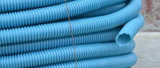
For domestic conditions, in order not to waste money, you can hang the cable that was used for hidden wiring. In order for the insulation to last longer, lay it in a corrugated pipe; its weight is not significant. There are reference tables indicating the brand and weight of the cable. You can look it up on the Internet; some sites have calculators for calculating the length and weight of wires and cables.
Tip No. 2 Use the calculator on this site https://kabelves.ru/
Table indicating the cable brand and weight in kg. by 1 meter
For high current loads, it is better to use special cables for overhead cable structures:
- AVT, AVTS, APT already have a built-in supporting steel cable;
- AVRG, ANRG, APVG, AVVG are suspended from a supporting steel cable.
Supporting and tensioning elements of cable wiring
These products are installed on the walls of buildings, structures between which tension is stretched. Depending on the material and diameter of the cable, the fastening design is selected:
- Tension bolt, hook and tension anchor are used for flexible multi-core industrial cables carrying heavy loads; rolled wire with a diameter of up to 6 mm can be used.
- Anchors for tensioning strings with a small diameter are designed for light wires with a cross-section of up to 6 mm at a distance of up to 10 meters, without lighting elements.
- Anchors for industrial cables and wire rods are capable of supporting heavy cables and lighting elements at a distance of up to 12 m without additional supports.
- Fasteners for stringing parallel lines are often used for dual purposes, for power supply to structures and placement of lighting lanterns. A power cable with a wire cross-section of 10 -35 mm/sq. is laid along one cable; on the second, lighting outlets and distribution boxes with copper wire 2.5 - 4 mm are laid.
Preparatory work
First you need to decide on the wire and its cross-section. We talked about how to calculate cable cross-sections in the corresponding article. After this, you need to measure the length, taking into account the entire route of wiring from the machine to the distribution panel. When choosing a cable and suspension elements, you need to take into account the weight of the wire in a given area, with a threefold safety margin. Since in difficult weather conditions the load on the suspended structure increases, it can cause breakage and loss of power. Mostly galvanized steel cable with a diameter of 4.6 to 6.8 mm is used. In cases where the length of the suspension is short and the weight is such that it can be neglected, instead of cable wiring, string wiring can be used (galvanized steel wire or varnished hot-rolled wire from 5 to 10 mm is pulled).
Installation technology
First you need to secure the anchor and the fastening elements of the cable wiring to the selected area. For the most part, these are steel plates pulled together on both sides of the wall with studs and rings welded to them for hanging the cable. The tension of the fastenings is done to strengthen and avoid their falling out, distributing the weight of the load evenly along the wall, and not at the fastening points.
Next, you need to secure the cable on one side with special loop cable clamps, on the other side, tighten it as much as possible, and use screw couplings to get it to the state of the string.
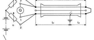
The height of the suspension should not be lower than 2.75 meters above the pedestrian area, and not less than 6 meters above the vehicle passage. All standards for overhead electrical wiring, including the distance between supports, are indicated in the diagram:
After installing the strings, they begin tying the cable with a bandage. To hang cable wiring on the street, you can use plastic clamps, galvanized iron strips, and galvanized binding wire. The distance between the bandage is 50-80 cm.
Where cable laying with a cable is allowed
In the PUE standards there is a concept of a type of open electrical wiring, which includes laying a cable using a cable or wire. Open electrical wiring is a method of wiring cables along the surface of the ceiling, walls, trusses, supports and building elements of buildings and structures. The concept of “construction element of buildings and structures” is quite vague and cannot fully answer the question of whether it is possible to lay a cable along a fence , but it gives a completely affirmative answer if the cable is laid along the wall of a building or structural elements.
Recommendations may be the following: laying the cable along the fence must be done if its height is not lower than 2 meters, and secondly, it is necessary to provide additional mechanical protection for the cable from damage. Clause 2.3.39 of the PUE clearly requires laying a cable line (provided the cable is unarmored) at an inaccessible height - at least 2 meters, and at a lower height - only with protection of the cable from mechanical damage (duct, pipe, angle steel, etc.) .
Recommendation from practice
When using a binding wire, it is necessary to prevent the core from cutting into the insulation; for this purpose, a gasket is made between the bandage and the wire made of insulating material. The winding area of the bandage should be distributed as much as possible by laying 7-10 turns of the bandage. When using plastic clamps, check their operational data. Otherwise, in frosty winters or very hot summers, you will find scattered clamps.
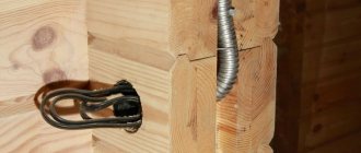
When laying the cable externally along the cable, it is also necessary to protect the line from the influence of the environment on the insulation, so it is recommended to stretch it in a corrugation, as shown in the photo below. This will then reduce the cost of operation and restoration of cable wiring.
If the span is short or there is no possibility of attaching the cable to the cable at the installation site, it is possible to assemble the suspension on the ground. The already prepared structure can be stretched and attached.
By following our instructions, you can independently conduct electrical wiring to separate buildings in the country. We also recommend watching a useful video that shows how to make a loop on a cable with your own hands:
That's all I wanted to tell you about how to install cable wiring with your own hands. As you can see, laying a cable along a cable is a rather labor-intensive task, but it is still within the power of a home handyman!
It will be interesting to read:
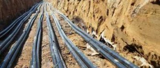
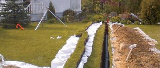
Conducting an electrical part in the ground is a costly and troublesome undertaking. Trenches are first dug at the site and special cables are purchased. The high cost and labor intensity forces us to look for simpler solutions. Air fastening is simpler and cheaper, especially string fastening, when fastening the cable to the cable. It allows you to reduce costs on materials, equipment, and labor. A significant limitation in the use of technology can only be the length and large plants between objects. When buildings are located nearby, the best solution is to install cable wiring. It is simply irreplaceable in warehouses, workshops and other production facilities. The main thing is to secure the elements correctly and securely. Otherwise, this is fraught with cable breakage and corresponding negative consequences.
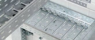
Rules for laying cables in channels
Cable laying in cable ducts is widely used. Cable ducts are made as standard from prefabricated reinforced concrete elements or from monolithic reinforced concrete (Fig. 5.7). In industrial premises, channels are covered with slabs at floor level.
When passing outside buildings in unprotected areas, the channels are laid underground at a depth of at least 300 mm, depending on the loads that may occur on the route.
If the territory is protected, then semi-underground channels with natural or artificial ventilation are used. But such channels should not interfere with transport communications and should not be combined with the general layout of the enterprise territory, since the level of overlap of such channels rises above the planning mark by 50...250 mm.
Cables in channels are laid on structures of various designs; laying along the bottom of the channel is also possible. The number of cables in a channel can be different and depends on the diameters of the cables and the brand of the typical channel; in channels of maximum size you can put up to 50... 60 power cables. If it is necessary to lay a large number of cables, it is possible to use double or triple-walled channels, but this makes it more difficult to make branches to individual consumers.
The method of laying cables in channels allows for inspection and repair of cable lines during operation, as well as laying a new cable or replacing an existing cable without excavation work.
When laying cables in channels, they are provided with reliable protection from mechanical damage.
In table Figure 5.7 shows the main dimensions of unified cable channels (designations B, B, N in Fig. 5.7).
The main straight tray channels, their ceilings, as well as the main elements of the prefabricated channels have a length of 3 m. The prefabricated elements for the tray and prefabricated channels in places of turns and branches have a length and width based on the possibility of laying cables in them with a voltage of up to 10 kV, cross-section 3×240 mm2, with cable bending radius R = 25d.
In areas where molten metal, high-temperature liquids, or substances that can damage cable sheaths may be spilled, the construction of cable ducts is not permitted.
Cable ducts outside buildings must be covered on top of removable slabs with earth with a layer thickness of 300 mm or more. In fenced areas accessible only to maintenance personnel, for example at substations, backfilling of cable channels on top of removable slabs is prohibited.
Backfilling of power cables laid in channels is prohibited. The arrangement of cables on structures, depending on the standard sizes of the channels, can be:
- on one wall of the channel on suspensions;
- on one channel wall on shelves;
- on both walls on suspensions;
- on one wall of the channel there are hangers, on the other wall there are shelves;
- on both walls of the channel on shelves;
- at the bottom of the channel with a depth of no more than 0.9 m.
Cable channels must be calculated taking into account the possibility of additional cable laying of at least 10% of the laid ones. The horizontal clear distance between structures when they are located on both sides (passage width) must be at least 300 mm for channels with a depth of up to 600 mm and at least 400 mm for channels with a depth of 900 and 1,200 mm.
Electrical wiring is an integral part of electrical power and lighting networks of alternating and direct current with voltage up to 1 kV. Depending on the designs of the conductors, the characteristics of the premises and the environment, conductors are laid in various ways: openly on insulating supports or directly on building foundations and structures, in pipelines, on steel trays, in steel boxes, along stretched steel cables and strings, and also hidden in structural elements of buildings.
According to the accepted method of laying conductors, electrical wiring is divided into open and hidden. In industrial buildings, to generally reduce the cost of work and save metal, it is recommended to use open pipeless wiring or replace steel pipes with non-metallic ones.
For open pipeless wiring, unprotected insulated wires and unarmored cables are used, therefore the routes of such wiring in their location must ensure the safety of the wiring from possible damage. Under normal production conditions, sufficient protection is considered to be the placement of wiring indoors at a height of at least 2.0...2.5 m from the finished floor or service area and at a height of at least 3.5...6.0 m from the ground level outside the premises. If necessary, open wiring is protected from touch and mechanical damage with special boxes or pipes.
Open wiring takes up a lot of space and increases the fire hazard, worsening the appearance of buildings and premises, but in general they are much more economical than hidden wiring. Hidden electrical wiring is carried out in the structural elements of buildings, in walls, floors, ceilings, and special channels. Office, office, and residential premises are now carried out only with hidden wiring.
Preparatory work for cable installation
To carry out the work efficiently, it is necessary to correctly calculate the cable cross-section. This parameter is directly dependent on the total power of the connected electrical appliances. The next step is to measure the distance between the machine and the switchboard. Be sure to take into account all climbs and turns. When all the necessary calculations have been carried out, a cable is selected. It must withstand the load exerted by the cable being laid along the entire length of the route. To eliminate the possibility of breakage during external installation, the strength of the cable and hanging elements is calculated based on three times the weight of the cable. Most often, galvanized cable with a diameter of 4.5 to 6.7 millimeters is used. The string method involves the use of galvanized steel wire or hot-rolled varnished wire with a thickness of 0.5 cm.
How to properly secure the cable?
The base must be strong and reliable, well secured. The cable and cable are installed using anchor fasteners. They are fixed on both sides of the wall or other base using bolts or studs. This allows you to evenly distribute the load and eliminate the possibility of fasteners falling out of the wall. The distance between anchors that are located in close proximity to each other should be less than 100 meters. To ensure greater reliability of fastening, additional anchors are installed every 30-40 centimeters. Between the cable suspensions the step is from 70 to 90 centimeters. The design provides a special loop clamp and a screw coupling, a manual winch or a pulley. They are located on opposite sides. The presence of these elements allows you to lift and tension the cable, as well as change its strength and stability. He is grounded. Under no circumstances should it be used as grounding. The degree of tension should not be maximum. The cable should not sag. You also shouldn’t be too zealous when pulling the cable. Overvoltage that occurs when exposed to low temperatures can cause it to burst.
Cable installation on supports and poles
When building networks, telecom operators are often faced with the inability to use cable ducts or buildings. For passage using the air suspension method, in such cases, installing the cable along lighting poles or power poles can greatly facilitate the task.
There are several standard installation methods: 1. Supporting. 2. Tension. 3. Combined.
Let's take a closer look at each of the methods.
1. Installation of the optical cable using support clamps.
Support clamps are used for areas where the cable runs in a straight line, the maximum angle of rotation when using such clamps is from 10 to 20°. Domestic and foreign manufacturers offer many options for clamps for supporting installation of self-supporting (ADSS) and figure-8 cables.
Clamps PPO-6.5/8.0-06 or ZP-8-1(2) Clamps PPO or ZP can be used on routes with the risk of falling trees or damage to poles. If a tree falls on the cable or the pole is damaged, the cable breaks out of the clamp and usually remains undamaged.
Examples of using PPO clamps in combination with various fastening units.
Spiral supporting clamps.
Spiral clamps are used for mounting self-supporting cable (ADSS) on power transmission towers, lighting and communication poles. Many modifications are available for different span lengths and cable termination strengths. The fastener consists of a protector to protect the cable sheath from damage, a power spiral and a thimble.
Support clamp SC30/34 or CS
A universal clamp for hanging “8-shaped cables”, can be fastened with a steel tape or with a bolt on wooden supports. Allows installation of cables with a cable diameter of 4 to 9 mm. It is characterized by simple and quick installation, but has a number of limitations. When using such clamps, it is important to accurately select the diameter of the cable; in practice, there have been cases of the cable slipping through the clamp; it is also important to strictly observe the recommended span length. The practice of using such clamps has shown that it is best to use them in a combined installation option (Alternating anchor and support clamps).
Supporting clamp NS 10/15.
NS 10/15 clamps are used for mounting ADSS cables with a diameter of up to 20 mm; it is recommended to use them on straight sections of the route. Based on experience in use, we can say that such clamps are good for short spans - up to 60-70 m; installation during rain is practically impossible, since the cable slips through the bushing.
2. Installation of the optical cable using tension clamps.
Tension (anchor) clamps are used for rigid cable fastening; they are used both at rotary, branch, end sections of installation, and along the entire length of the route. Tension anchor clamps AN-250(500,700,800), AC 6(7), PA 06(07) , Anchor clamps can be used with both “8-shaped” and self-supporting cables. Clamps for hanging cables with a supporting element made of steel cable allow you to quickly install the cable, without stripping and separating the power element. The plastic loop on the clamp cable provides insulation of the load-bearing element in the event of a short-circuit to ground of the support. It is NOT recommended to use such clamps when installing a cable with a strength element made of steel wire; under long-term load, the teeth of the wedges begin to slip along the smooth wire, which leads to damage to the cable.
Tension spiral clamps.
Tension spiral clamps are used for installation of self-supporting cables (ADSS) on power line supports, power poles, lighting, and railway contact networks. The fastener consists of a protector, a loop-shaped power spiral coated with a special abrasive and a thimble.
3. Installation of optical cable using the combined suspension method.
The combined suspension method is widely used when using PPO clamps, SC30\34. The essence of the method is alternating support and tension (anchor) clamps. In this way, the reliability of the line can be increased and construction and operating costs can be reduced. The optimal ratio is 4 support clamps to one tension clamp.
Features of fastening methods
The use of a design in the form of a tray, box or pipe allows for additional protection of the wires from the harmful effects of the environment. This fastening method is advisable to use where the cable is directly affected by both low and high temperatures. Metal fasteners are less versatile and require additional precautions. They should not violate the insulation of the cable being laid. In other words, it is necessary to use additional elements placed under steel and iron buckles, for example, insulating material.
The cable is fastened directly to the cable using various fasteners - galvanized iron sheets, steel strips, plastic clamps. The first two fastening options are considered preferable. Plastic elements are selected taking into account operating conditions so that they do not require replacement every season.
Is it possible to replace a cable with a rope?
Often, some people decide to use a rope rather than a cable. Such a replacement cannot be made, since it does not have the required properties. Fabric fibers are easily destroyed under the influence of external negative factors. The rope easily stretches, frays and even breaks. Loss of strength can lead to sagging. If the wire breaks, it will create a dangerous situation where the electrical current could kill someone nearby.
FEDERAL UNIT PRICE FOR FARMS 08-02-149-01
| Name | Unit |
| Cable up to 35 kV, suspended on a cable, weight of 1 m of cable: up to 1 kg | 100 m cable |
| Scope of work | |
| 01. Installation and removal of the winch. 02. Installing and removing the drum. 03. Installation and removal of rollers. 04. Installation and dismantling of intercom. 05. Laying cable and cable. 06. Checking the condition of cable insulation before and after installation. 07. Marking. |
The price does not contain overhead costs and estimated profits; accordingly, the direct costs of work for the period 2000
(prices of the Moscow region), which are calculated based on
2009
. For further calculations, this cost must be multiplied by the conversion index to current prices.
You can go to the pricing page, which is calculated based on the 2014 edition standards with additions 1
| Total (RUB) | Workers' compensation | Machine operation | Pay for drivers | Cost of materials | Labor costs (person-hours) |
| 3975,25 | 164,5 | 2360,25 | 216,68 | 1450,5 | 17,1 |
TOTAL PRICE: RUB 3,975.25.
Look at the cost of this standard at current prices open page
Look at the resource part of the price in the GESNm standard 08-02-149-01
When used in an estimate, the price requires indexation to translate into current prices. The price is based on the GESN-2001 standards, as amended in 2009.
in
2000
.