To build any cable network (power and low-current cables, signal lines, security and fire alarms, SCS and LAN, etc.), it is necessary to lay a large number of cables that come out of the work premises.
The use of metal cable trays to create a system of cable channels on site is one of the standard solutions. Trays are installed in technical rooms, cable tunnels and shafts, mounted in corridors, workshops and even in offices and shops.
The mounting methods below are suitable for all types of our trays:
| Cable tray "Quick installation" | Cable tray "Standard" | Ladder tray (cable ladder) | Wire tray |
Since the load on the trays is large due to the large number of cables being laid, it is necessary to use reliable methods for installing and fastening the trays.
Let's look at the main methods of attaching trays. For convenience, the circuits are divided into three groups: installation to the wall, ceiling and floor.
Attaching the tray to the wall
A popular method of attaching a tray is organized through the use of cable shelves (consoles, wall brackets, console brackets).
In turn, shelves (brackets, consoles) can be attached directly to the wall or to special racks or profiles that ensure reliability and durability. The main advantage of using cable racks when installing a route on a wall is the ability to install several parallel tiers of cable trays for separate cable routing. Thus, cable standards, for example, recommend that optical cables be laid separately from copper cables, which determines the need to install several groups of trays in parallel.
When laying the route in a vertical plane, it is possible to use a bracket-bracket.
Click on the picture to go to the corresponding diagram
| Mounting to the wall using a bracket (shelf, console) | Mounting the tray on the wall on a C-shaped bracket | Mounting the tray on the wall using a bracket |
Advantages of using shelves and brackets:
- Simplicity and speed of installation
- Strength, reliability and high load-bearing capacity of the structure
- Versatility:
- on the basis of one profile of different lengths, it is possible to assemble wall, ceiling and floor structures with different suspension heights and different lengths of shelves;
- the design of many consoles (brackets, shelves) allows mounting mounting elements both above and below the console itself;
- Possibility of mounting trays not only horizontally, but also in a vertical position
- A wide range of shelves and consoles/brackets for a wide range of loads - from low to extremely high.
A similar method can be considered for attaching cable shelves to racks (mounting profile) attached vertically to the floor, ceiling or other structural elements of the building (structure).
Load-bearing structures: cable racks and shelves - here you will find additional information about the “classic” GEM Shelf-Rack design.
Types of cable trays
Known types of cable management trays differ based on a number of factors, which are listed below:
- The material from which the boxes are made (stainless steel, plastic, galvanized or concrete).
- Place of installation (plinths, floors, cornices, underground, etc.).
- The presence of dividing partitions.
note:
Laying cables in concrete trays is most often used when constructing underground trench routes.
For easy comparison of the characteristics of trays, their main types are presented in table form.
| Material | Advantages | Flaws | Functionality |
| Low carbon steel | Strength, resistance to mechanical deformation | Susceptibility to corrosion, difficulty of installation, significant weight. | Partitions |
| Stainless steel | Same plus corrosion resistance | Expensive | Partitions and perforations |
| Galvanization | Strength, lightness, corrosion resistance | None | Presence of perforations and partitions |
| Plastic | Cheap, light and easy to install | Low resistance to deformation, fragility | Large selection of designs, availability of partitions |
| Concrete | Strength, reliability, resistance to deformation | Significant weight, difficulty of installation, hygroscopicity | Concrete partitions, side brackets |
Additional Information:
The presence of partitions allows, according to the PUE, the laying of power cables in trays separately from low-current (control) lines.
Plastic boxes attract the attention of users with the following properties:
- in residential and work areas they can be installed at any level (near the desktop, for example, or near the baseboard);
- the insides of the tray are divided by partitions into sections in which wires for various functional purposes are laid (photo on the left);
- The rules for laying cables in trays allow for their installation directly on the floor or ceiling.
Unlike plastic, the choice of placement of steel boxes is significantly limited by safety requirements in terms of electrical safety.
Attaching the tray to the ceiling and ceiling structures
Click on the picture to go to the corresponding diagram
| Ceiling mounting with bracket and stand | Installing a tray using a mounting profile and stand | Mounting to the ceiling on a C-shaped suspension | Mounting the tray to the ceiling using a stud |
| Using punched paper tape to mount the tray | Installation to corrugated sheets | Attaching the cable route to the ceiling beam | Mounting the tray to the ceiling using a stud and bracket |
Recommendations for the method of attaching the tray to ceiling racks:
The method is similar to attaching shelves and brackets to the wall, with the only exception that the brackets are not attached to the wall, but to special ceiling racks or to prefabricated structures made of ceiling supports and a mounting profile.
- The trays are fastened to the ceiling using brackets using a prefabricated unit - a ceiling bracket.
- The ceiling bracket assembly is attached to the ceiling using bolt anchors or a drive-in anchor. The anchor is driven using a special tool for driving the anchor, and then the bolts are screwed into it. Anchor installation makes it easy to sort out or dismantle mounting structures.
- The ceiling bracket should be installed every 1-1.5 meters (i.e., just like with any other installation method: at the joints and in the middle of the cable tray).
In a similar way, installation of trays is carried out using free-standing (without support to the wall) floor racks.
Recommendations for using perforated steel tape:
- Mounting on punched tape is the cheapest solution, but due to insufficient rigidity it has limited use: low load, low suspension height, small width of cable trays, difficulties with expanding mounting structures.
- The punched paper tape is attached to the ceiling using bolts screwed into anchors.
- The channels are attached to the punched paper tape using screws, nuts and washers.
- The distance is selected in the same way as when fastening with brackets - at the joints of the trays and in the middle of the tray (1-1.5 m).
As a more convenient, practical and reliable alternative to this method, it is proposed to attach the trays to the ceiling using C-shaped hangers.
About using studs and mounting profile:
To attach the tray to the ceiling, which is used for laying a large number of cables at sites, two studs and profiles are mainly used, which are mounted between the studs.
For cable support systems with low loads, you can use one stud with fastening the profiles in the middle. This makes it possible to simplify and speed up installation, while reducing the cost of installation structures, but sets strict restrictions on the load-bearing capacity.
By installing several profiles, you can create several parallel cable channels.
How to properly install cables in trays and boxes: instructions and step-by-step description
We would like to devote today’s article to wires that are placed in boxes or trays.
This installation method has tangible advantages: it is quite cheap; facilitates further monitoring and repair of wires; and it looks quite aesthetically pleasing.
But in order to do everything correctly and beautifully, you must comply with some conditions and rules, which we want to talk about.
The first thing you should pay attention to is that for this type of installation a work project must be drawn up that will comply with the standards of the Electrical Installation Rules, namely parts 2.1; 2.3, as well as paragraphs of Building Codes and Regulations 3.05.06-85, and other norms and standards developed by the state.
During installation, you must follow the developed project and not deviate from its points.
The designer, when developing your electrical network laying plan, must, in accordance with all the rules, select the type of tray, taking into account the degree of protection, design properties, and the raw materials from which the box is made.
Also, when developing a project, a laying plan is drawn up, which indicates exactly how the cables will be placed in the trays - in bundles, single strands and other aspects of the work.
After completing the project, you must contact special authorities to obtain permission to carry out the work.
We would like to draw your attention to the fact that such work with the development of projects in our country can be carried out by special institutions that have received the appropriate permits to carry out the above actions.
Having dealt with the documentary side of the work, let’s move on to the practical side. Let's look at how you can lay cables in trays and boxes, and what you need for this.
Cables can be installed in different ways, it can be bundled or packaged, it can be laid with single cores, it can also be laid in layers.
Depending on the type of wire installation, the distance between the electrical conductors should be taken into account.
So, if you install wires in rows, then this distance should be 5mm; in other types of installation, this figure should be multiplied by 4, that is, it should be at least 20mm.
You can ignore the above distance only if multi-row installation is used.
When assembling in a bundle, no more than 12 cables can be folded into a bundle, while the maximum radius of the bundle can reach 10 cm.
When you need to lay them on trays in a horizontal position, it is better to fold the wires in bundles with a distance between nodes of at least 4 and a half meters.
If the installation area is horizontal and straight, then the beams can be ignored and another, simpler installation method can be chosen.
When the tray is in a vertical position, the distance between the nodes must be at least 1 meter.
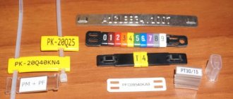
After the entire cable system is folded and attached to jumpers, the pitch length of the current-carrying path is measured.
This is done using a special cord in order to correctly cut the electrical zones in the future. Then all the threads are formed into bundles and marked with the necessary tags.
Next, after installing the entire circuit, they check with a measuring device for damage and breaks. A megohmmeter is also used to measure the resistance of cable insulation.
When working with wires, you must also take into account external factors that may affect the condition of the cable.
So, if the air temperature is higher than or equal to -15 C, then there is no need to use heating of the wires, but if the temperature is from -15 to -40 C, then heating during installation is required. At temperatures above -40С, installation is prohibited.
When laying wires in boxes and trays, it is imperative to leave a reserve of cable length in case the wire changes its parameters due to temperature changes.
At the same time, the cable is laid in such a way that there are no rings or turns, but only straight lines of wires.
You should also additionally install sun protection devices if cable trays are installed outdoors.
Particular attention should be paid to the installation of the wire in heavy areas and parts of its connection. It is necessary to minimize cuts on bridges and other damage.
Cables must be secured at the extreme point of support, at bends, couplings and other connecting places. That is, you need to put every effort into ensuring that the trays with wires are solid and intact.
We should not forget about the possibility of cable deformation due to its mass, the influence of temperature fluctuations, and magnetic influences due to a short circuit.
When, during cable installation, power lines cross with other communications, such as gas pipelines, pipelines and others, then it is necessary to adhere to the distances specified in the PUE, namely sections 2.1, 2.3 and so on.
So, for example, when installing next to a pipeline, the distance between the box and the pipe should be more than 5 cm, when laying parallel - more than 10 cm; When laying near gas pipes, a distance of at least 25 cm must be maintained.
When performing work, there is no need to completely fill the boxes with wires, as this will interfere with further network service and self-cooling of the wires. You need to fill no more than half of the entire tray space.
Do not forget about further grounding of the network. To perform it efficiently, it is necessary to ensure a metallic connection of the wires in the tray, because when grounding only the extreme points of the structure will be involved.
If the wires are laid for a living space, then they should be mounted higher than 2 m from the floor. But this indicator does not matter when the room is intended to be used by people who are trained in the correct use of electrical networks.
When the network is installed in an accessible place, opening boxes are used to allow easy access to the wires if necessary. At the same time, in closed areas the wires are laid in solid structures.
When choosing an installation method, pay attention to such an indicator as humidity, which can cause condensation to accumulate in the box or tray.
In general, this is all I wanted to tell you about laying wires in trays or boxes. We hope that our story will be useful to you and will be useful in construction work!
Attaching the tray to the floor
These schemes are variations of the already discussed methods of laying a cable route along a ceiling or wall. Thus, in the first two schemes, the ceiling mount was replaced with a floor mount, and the universal bracket-bracket is just as easily mounted on the floor as on the wall.
Click on the picture to go to the corresponding diagram
| Fastening to the floor using a bracket and stand | Installing a tray using a mounting profile and stand | Using the Floor Mounting Bracket |
Normative documents
The laying of cables and wires must be carried out in accordance with the project, special instructions, as well as taking into account the requirements of current regulatory documents: - SNiP 3.05.06-85 “Electrical devices”; — GOST R “Electrical installations of buildings. Part 5. Selection and installation of electrical equipment”, Chapter 52 “electrical wiring”; — “Rules for electrical installations.”
These norms and rules must be followed both at the design stage and directly during installation work of the cable support system.
The main task of the installers is to assemble a system of cable trays and boxes and lay electrical cables and wires in them in strict accordance with the electrical design. The design, material and degree of protection of cable-supporting elements, as well as the method of laying cables and wires in the cross-section of cable trays (single, bundled or multi-layered) are determined by the designer and reflected in the design documentation.
Laying cables and wires without a project coordinated with the relevant services and approved in the prescribed manner is not permitted.
Specialized installation organizations that have the appropriate permits for carrying out these works and equipment are allowed to carry out work on wiring power lines, connecting equipment and wiring current-carrying lines.
Grounding trays to each other PUE
Before putting cable routes into operation, specialists take a number of additional measures to increase the safety of the equipment. One such measure is grounding cable trays. Since there are different types of trays, differences can be found in the grounding process. In particular, this applies to wire types.
In any case, the installation must comply with the regulatory requirements of GOST standards and electrical installation rules.
Grounding trays using PUE - All about electricity
In order to commission cable routes, it is necessary to take various measures to improve the safety of the equipment. One of these measures is the grounding of cable trays. This process must be given special attention in order to do everything correctly and in accordance with GOST standards. It should also be noted that cable trays come in many different types, so the connection method is different.
They can be wire, sheet, perforated and all-metal. We will talk about how to ground each of the design options below.
Installation instructions
Technical requirements
Before installing and starting to operate cable ladders and trays, trays for lamps, busbars, you should familiarize yourself with the requirements of national and industry standards, technical specifications, and safety measures for the installation and operation of the above products.
General instructions for installing cable trays and cable ladders "Meka"
Installation must be carried out in such a way that the deflection in cable ladders, cable trays and trays for lamps that are in the field of view does not exceed L/200 (L is the distance between supports).
In cable ladders, cable trays and lighting trays used in industry and out of sight, the deflection should not exceed L/100.
In practice, the value L/200 means that, for example, with a distance between supports of 3 meters, the deflection can reach a maximum of 15 mm. When calculating the deflection, it is also necessary to additionally take into account the safety factor, which is approximately 50% of the existing load.
Load diagrams and maximum loads, as well as explanations of the diagrams, are given in the Meka catalogues.
At the ends of cable ladders, cable trays and trays for lamps, as well as between them, sufficient space should be left for their possible thermal expansion.
The coefficient of thermal expansion of steel is 0.000012 m/ºC. Thermal expansion can be calculated using the following formula: change in temperature x 0.000012 x length. If the length of the cable run is 100 m and the temperature change is 40 ºC, then the change in length will be: 40 x 0.000012 x 100 = 0.048 m, or 48 mm.
When installing cable ladders, cable trays and trays for lamps, the load capacity of the supporting elements, as well as the strength of fastening and facing materials should be taken into account.
In places where vertical cable ladders or trays may be subject to mechanical damage, they must be protected to a height of up to 1.5 meters with protective covers.
Passage places
In places where there are passages through fire-resistant walls, the cable ladder and tray should be cut off next to the wall. At the border of fire hazardous areas, installation openings must correspond to the fire resistance of the structure in which the passage is made.
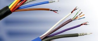
Installation of electrical wiring and cables
Electrical wires and braided cables are used as electrical wiring.
When installing electrical wiring and cables, the influence of external factors, such as temperature, should be taken into account. The effect of the maximum DC current on the temperature of the wires and cables must also be taken into account.
When installing a cable ladder or tray horizontally, the wires and cables are usually laid out neatly and without fastening. When a cable ladder or tray is installed vertically or at an angle, the wires and cables are secured to the ladder or tray with suitable fasteners at suitably selected intervals.
Equipment
Equipment installed on cable ladders and trays, as well as lighting trays, such as distribution boxes, must be secured firmly and in such a way that it does not fall directly into the conductor space. If necessary, mounting bases are used to secure equipment.
Use of high voltage cable systems
Cable ladders KS80 and KSF80 can be used to lay high-voltage cables using the clamps provided for them during installation.
Grounding (potential equalization)
In each building it is necessary to carry out basic potential equalization. The purpose of basic potential equalization is to prevent the occurrence of dangerous voltage differences between simultaneously contacting conductive parts. When equalizing potentials, live and current-carrying parts are brought to the same potential so that there is no potential difference between them.
Objects related to the field of potential equalization are metal pipes (utility networks), metal parts of building structures, as well as iron reinforcement of reinforced concrete structures. Metal cable support systems can also be considered as structures related to the field of potential equalization.
Grounding (potential equalization) of cable channels
The duct system usually does not need to be grounded or connected to an equipotential bonding wire if braided cables (NYM type) are installed in the duct. The exceptions are hospitals, explosive premises (in relation to which
Atex rules apply). Grounding and potential equalization may also be necessary in specific design solutions.
Grounding (potential equalization) of cable ladders and trays
Cable ladders and trays can be considered as current conductors, so they must be connected to the building's main potential equalization rail at least in one place.
Especially during industrial installation, it is necessary to pay maximum attention to the reliability of grounding of the entire cable support system. In industrial environments, it is recommended that cable trays and ladders be grounded at, for example, 40 m intervals unless they are securely attached to a conductive structure (eg a grounded steel column).
With the SSR, SSU and NL connectors used in the KS20 and KS80 series cable ladders, a sufficient electrical connection is achieved without the need to install a separate ground wire after the ladder junction.
Electrical conductivity of cable ladders and trays
At the initiative of Meka Pro JSC, a study of the electrical conductivity of cable ladders and trays was carried out at SGS Fimko Oy (as part of the IEC 61537:2006 standard, clause 11.1).
Electrical conductivity of Meka cable ladders
| Treatment | Name | Voltage drop [mV] | Resistance [mΩ] |
| Galvanized | KS20 PG + SSC PG | 6,1 | 0,24 |
| KS20 PG + SSR PG | 3,3 | 0,13 | |
| KS20 PG + NL PG | 5,9 | 0,24 | |
| KS20 PG | 7,6 | 0,3 | |
| Hot-dip galvanized | KS80 HDG + SSR HDG | 4,2 | 0,17 |
| KS80 HDG + SSU HDG | 3,6 | 0,14 | |
| KS80 HDG + NL HDG | 9,7 | 0,39 | |
| KS80 HDG+ NL-TK HDG | 6,4 | 0,26 | |
| KS80 HDG | 5,4 | 0,22 | |
| KSF80 HDG + KSF80 HDG (bolt connection) | 3,9 | 0,16 | |
| KSF80 HDG + KSF-NL HDG (direct connection) | 3,8 | 0,15 | |
| KSF80 HDG + KSF-NL HDG (vertical connection) | 7,4 | 0,3 | |
| KSF80 HDG | 5,5 | 0,22 | |
| Stainless steel | HST KS80 + HST SSU | 16,6 | 0,66 |
| HST KS80 | 31 | 1,24 |
Electrical conductivity of Meka cable trays
| Treatment | Name | Voltage drop [mV] | Resistance [mΩ] |
| Painted trays and galvanized connections | KRA-100 M + RSS-100 PG | 15,7 | 0,63 |
| KRA-300 M + RSS-300 PG | 8,9 | 0,36 | |
| KRA-500 M + RSS-500 PG | 5,8 | 0,23 | |
| KRA-100 M + RVS-100 PG | 27,3 | 1,09 | |
| KRA-300 M + RVS-300 PG | 24,1 | 0,96 | |
| KRA-500 M + RVS-500 PG | 14,8 | 0,59 | |
| KRB-300 M + RSS-300 PG | 8,1 | 0,32 | |
| KRB-300 M + RVS-300 PG | 28,5 | 1,14 | |
| Painted trays | KRA-100 M | 10,7 | 0,43 |
| KRA-300 M | 3,8 | 0,15 | |
| KRA-500 M | 1,8 | 0,072 | |
| KRB-300 M | 4,8 | 0,19 | |
| Galvanized trays and galvanized connections | KRC-100 + KRC J-100 PG | 10,2 | 0,41 |
| KRC-150 + KRC J-150 PG | 7,5 | 0,3 | |
| KRC-200 + KRC J-200 PG | 5,9 | 0,24 | |
| Galvanized trays | KRC-100PG | 19,2 | 0,77 |
| KRC-150PG | 13,8 | 0,55 | |
| KRC-200PG | 8,7 | 0,35 |
Electrical conductivity of Meka boxes for hanging luminaires
| Treatment | Name | Voltage drop [mV] | Resistance [mΩ] |
| Painted boxes and galvanized connections | MEK 70 M + MEK J-70 PG | 10,4 | 0,42 |
| MEK 70 M + MEK NL PG | 33,6 | 1,34 | |
| MEK 110 M + MEK J-110 PG | 10,6 | 0,42 | |
| MEK 110 M + MEK NL PG | 7,9 | 0,32 | |
| Painted boxes | MEK 70 M | 35,9 | 1,44 |
| MEK 110 M | 7,3 | 0,29 |
Fire resistance of cable-supporting structures
The manufactured cable support structures were tested for fire resistance in the VTT laboratories in Finland during 2013-2014. and “PozhStandart” in Moscow in 2011.
When conducting the tests, the conditions, requirements and methods of the standards EN 1363-1, DIN 4102-12 and GOST-R 30247.1 were taken into account, as well as the recommendations of the technical report “Technical Report (TR): Cable management systems (CMS) for fire resistant installations”. The TR:CMS report is being prepared by the IEC and is likely to be used as the basis for a European EN standard that will replace current regional standards.
Cable ladders KS20, KS80 and KSF80, cable trays KRA, wire trays WMT, trays MEK for hanging luminaires, as well as parts for hanging and mounting the listed products were tested for fire resistance.
Classification of Meka trays for fire resistance.
| Classification according to GOST 30247.1-94 | Product group |
| R60 | Wire trays WMT |
| R90 | Cable ladders KS20 (except KS20 K) |
| Trays for MEK lamps | |
| Cable trays CT | |
| R120 | Cable ladders KS80 |
| European classification | Product group |
| E60 | Cable ladders KS20 (except KS20 K), KS80 and KSF80 |
| MEK trays for luminaires | |
| Wire trays WMT | |
| E90 | Cable trays KRA |
Operation of cable ladders, cable trays and lighting trays
During operation, it is recommended to comply with the requirements of national standards, technical specifications and safety measures.
Recommendations:
- The compliance of electrical circuits of cable routes with actual operational parameters must be checked at least once every 2 years with a check mark on them.
- If the operating conditions of electrical equipment change, appropriate additions are made to the instructions for operating cable routes. The instructions are revised at least once every 3 years.
- Checking the presence of a circuit between the grounding electrodes and the grounded elements of the cable route must be carried out every time the equipment is rearranged and after each repair of the grounding electrodes.
- In case of damage to the protective layer of cable ladders and trays, the damaged area should be treated with a coating that matches the coating of the product (zinc or powder paint).
Safety Precautions and Manufacturer's Responsibility
- Cable trays and ladders are intended for cable routing only.
- When installing cable trays and ladders and other electrical installation products, it is necessary to take into account the load capacity of the supporting elements, as well as the strength of fastening and facing materials.
- Cable trays and ladders must not be used as stairs or walking platforms.
- When installing and operating, follow the safety precautions specified at the site, territory and other local requirements.
- The manufacturer is not responsible for direct or indirect damage caused by improper use of products or failure to comply with safety precautions.
Basic recommendations for storing Meka trays
- Cable trays and ladders should be stored in their original original packaging. Factory packages can be stacked in height, but the height should not be more than two factory packages vertically. *)
- Cable trays and ladders and their accessories should be stored in dry and low-moisture areas. It is not recommended to store products outdoors.
- Trays and ladders should be stored on a level surface. Storage of trays and ladders in a vertical position is not allowed.
- Accessories, trays and ladders can be stored in dry and low-humidity areas for 5 years without loss of quality.
- Aluminum products, cable ducts, service racks and busbar trunking should be stored in dry rooms, in places that do not pose a risk of damage to the products.