During the construction of buildings and structures, there comes a time when it is necessary to install electrical wiring. Questions arise about what brand of wires or cables to choose, what cross-section and insulation class they should have. The material from which the current-carrying cores are made is selected based on the load for which the designed networks will be designed.
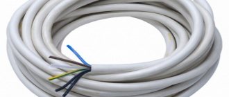
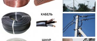
Wires and cables, general view
Features of electrical wires
With all the variety of cable products and a huge selection of wires for laying electrical networks, there are selection rules. It is not necessary to memorize all brands of cables and wires; you need to be able to read and decipher their markings. First, it’s worth figuring out the difference between a wire and a cable.
Wire – A conductor used to connect two sections of a circuit. May have one or more conductive wires. The veins can be:
- naked;
- isolated;
- single-core;
- stranded.
Bare lines are used where touching live wires is impossible. In most cases they are used for overhead power lines.
The insulating coating is used in one or two layers. Wires that have two or three conductors in double insulation are confused with a cable. The confusion occurs due to the fact that insulation covers each core, and on the outside there is a general polymer or other coating. Such conductors are used inside electrical devices, panels or cabinets. In everyday life, they are hidden in the wall or laid in special channels.
Insulated products are used everywhere. Depending on the degree of electrical safety of the room and the installation location, the insulation class is selected.
Stranded conductors are used where small radius bends are required when laying complex routes where single-core analogues cannot pass. This type of current conductors is convenient to install in cable ducts. Single-core wires are more difficult to bend in such conditions, force must be applied, and there is a risk of damage to the wire.
For your information. Marking APPV 3*2.5 means a wire with aluminum conductors, polyvinyl chloride insulation, flat, having a dividing base. The meaning of the marking is clarified in the reference literature.
APPV wire 2.5 * 3 with dividing base
In terms of structure, a cable consists of several individually insulated strands placed in a protective outer layer of dielectric material. The space between the cores and the shell is filled with paper tapes, plastic threads or cable yarn to prevent sticking. Additionally, the product can be reinforced with armor made of tapes or steel braiding to protect against mechanical damage.
Three-phase cable with neutral core and grounding conductor
What is bending moment
In the first part of the cycle, we already found out that any influences on the material and all types of resistance can be decomposed along the x, y, z axes into forces and moments and obtain six equilibrium equations.
However, if we have already talked about forces in sufficient detail, we have not yet spoken about moments.
Moment is the amount of “twist”. For a material point, it is calculated by multiplying the force by the arm:
Moment is the product of force and arm.
Draw a line from the point perpendicular to the force, multiply its length by the force. This will be the moment of torsion of this point.
Among other things, the moment can be determined by a pair of parallel but opposite forces. Then the resultant force will not change, and the body will tend to bend.
The torsional moment Maz is given by a pair of forces.
Conductor cross-sectional area
Neva MT-324
In drawings, a wire section is an image of a figure formed by cutting a part with a plane. What is a cross section in electrical engineering? Applicable to electricity, considers the cross-section of a conductor at right angles to its longitudinal side. The cross-section of the core through which electrons pass is a circle and is measured in mm2.
Important! The diameter of the core is often confused with its cross-section. To find out what cross-section the wire has, you need to determine the area of the resulting circle by calculating it using the formula.
Conductor cross section
Since the cross-section of the wire is a circle, the area is calculated using the formula:
S cr = π*R2, where:
- S cr. – area of the circle, mm2;
- π = 3.14;
- R – radius of the circle, mm.
Knowing the cross-sectional area of the core, its length and the resistivity of the material from which it is made, it is possible to calculate the resistance of the conductor to the electric current flowing through it.
Information. Considering that the radius is equal to 1/2 the diameter, the formula can be transformed for ease of use. It will look like Skr = π*D2/4 = 0.8 * D2. To calculate the cross-sectional area of a conductor, the diameter value is often used.
An incorrectly selected wire diameter causes it to overheat and melt, which, in turn, can cause a fire in the electrical wiring.
Conventions when making sections
If the secant plane passes through the axis of the surface of rotation that bounds the hole or recess, then the contour of the hole or recess in the section is shown in full (Fig. 25, a, b), that is, the section is made according to the type of cut.
In the case of a non-circular hole and if, when making a section, the image breaks up into separate independent parts, then instead of a section it is necessary to use cuts (Fig. 25, c).
Correspondence of wire diameters and cross-sectional area
Electrical safety briefing for 1 group
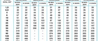
Using the formula to calculate the cross-sectional area each time is a long process. It is more practical to use ready-made tables.
Table for conductors with copper cores
| d, mm | Ssection, mm2 | Power (P), for 220 V network, kW | Current, A | Power (P), for 380 V network, kW |
| 1,12 | 1,0 | 3,0 | 14 | 5,3 |
| 1,38 | 1,5 | 3,3 | 15 | 5,7 |
| 1,59 | 2,0 | 4,1 | 19 | 7,2 |
| 1,78 | 2,5 | 4,6 | 21 | 7,9 |
| 2,26 | 4,0 | 5,9 | 27 | 10.0 |
| 2,76 | 6,0 | 7,7 | 34 | 12,0 |
| Z.57 | 10,0 | 11,0 | 50 | 19,0 |
| 4,51 | 16,0 | 17,0 | 80 | 30,0 |
| 6,68 | Z5.0 | 29,0 | 135 | 51,0 |
The table below shows the following values:
- conductor diameter;
- cross section corresponding to this diameter;
- permissible current value for this section;
- load power that can be connected through this conductor to 220/380 V networks.
When choosing a wire or cable from a directory, you must first decide on the material from which the cores are made.
The concept of view, section and section
Sections, sections, views - these are the three main categories in the construction of engineering graphics drawings. They are different in their content. Therefore they deserve detailed consideration.
A view is a drawing of the surface of a part that is turned towards the observer. To simplify the engineer’s work, in such a drawing it is allowed to indicate invisible surfaces with dotted lines.
The main view is the front view of the part. But there are other varieties of it. The part is also shown on the left, above, right, behind or below.
A section is a drawing of a part that has been mentally cut by a plane (one or more). The section will show what is in the section plane and beyond it.
But a section is also called such an examination of an element in which it is cut in a certain way by a plane. But the figure shows only what was in this cutting plane. What is behind it is not visible in the drawing.
These definitions must be taken into account by a specialist performing technological tasks using engineering graphics.
How to determine the cross-section of a stranded wire
Stranded wire consists of several cores combined. Therefore, the total cross section can be determined in two steps:
- the cross-sectional area of one core is calculated;
- the resulting value is multiplied by the number of cores in the wire.
When connecting, the ends of wires with many cores must be crimped with a special sleeve of a suitable diameter. For this, crimping pliers are used.
Cross section of single-core and stranded wires
Symmetry
Section types can be placed in the gap that forms between parts of one image. This can be done on the continuation of the cut plane trace. But this approach is only permissible with a symmetrical figure, which is obtained during the dissection. The section is placed on any part of the drawing field. It is also acceptable to make a turn.
For symmetrical sections, the trace of the plane is not depicted in the drawing. There is also no inscription on this cut.
Asymmetrical sections are made in a gap or superimposed on a drawing. The trace of the plane for such graphics is depicted, but not written in letters. There is also no inscription.
The section taken out is outlined with a thick, continuous outline. If it is applied, a thin, continuous line is used to indicate it.
If an object has several identical sections, their outline is indicated by one letter. Only one slice is drawn.
Self-calculation
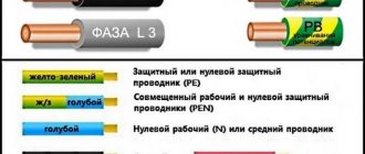
Sometimes you have to deal with a wire without markings. This is not a reason to refuse to use it. First, find out what material the core is made of. They are distinguished by color: white aluminum, red copper, yellow brass. After this, we begin to calculate the cross-sectional area. To do this, find out the diameter of the conductor by first removing the insulation from it; in the case of a multi-core wire, by untangling one core.
The diameter can be determined in several ways, for example:
- using a caliper or micrometer;
- pencil and ruler.
The second method gives an approximate result and is used only as a last resort.
Calipers
You can measure wires of any size using a caliper. To do this, place the wire between the jaws of the caliper and look at the scale divisions. Whole numbers of millimeters are counted on the upper scale, decimal fractions of a millimeter on the lower scale.
Pencil + ruler
If you don’t have a meter at hand, and the length of the bare part of the wire being measured allows you to wind it onto a pencil turn to turn with a length of at least 1 cm, then use this method. The number of turns N that fit on a segment L = 1 cm is counted. The diameter value is obtained by dividing the length of the segment by the number of turns. The measurement accuracy depends on the winding density and its length.
Table
After the diameter is determined by one of the methods, Ssection is determined using a formula or using tables.
The simplest table for wire diameters up to 4.5 mm
| Wire diameter, mm | Section, mm | Wire diameter, mm | Section, mm |
| 0,8 | 0,5 | 2 | 3 |
| 1,0 | 0,75 | 2,3 | 4 |
| 1,1 | 1 | 2,5 | 5 |
| 1,2 | 1,2 | 2,8 | 6 |
| 1,4 | 1,5 | 3,2 | 8 |
| 1,6 | 2 | 3,6 | 10 |
| 1,8 | 2,5 | 4,5 | 16 |
More accurate values can be selected from the tables located in the Rules for Electrical Installation Devices (PUE).
Image performance standard
The execution of schematic images, their sections, various types of sections, cones, beams, and their application to drawings are regulated by various standards. The main one is the Unified System of Design Documentation (USKD) “Images - views, sections, sections.”
This GOST was introduced on January 1, 1968. He stipulates that the image is considered as a projection of an object onto a plane at a certain angle. GOST “Images - views, sections, sections” says that there should be a minimum number of such drawings. But thanks to them, the specialist must obtain complete information about the object.
Therefore, according to their content, GOST divides all images into types, sections and sections. This document also establishes the types of designations, inscriptions and signs.
GOST 2.305-08 regulates that all images must be applied to the drawing using orthogonal (rectangular) projection technology. Ideally, the object is located midway between the observer and the design plane.
But due to the fact that some nodes and elements require consideration from a different angle, this condition is violated. Therefore, the types of sections, drawings of which are used in production conditions, are called images. To implement them, the standards regulate a number of simplifications and abbreviations.
How to find out the cross-section of the input wire
The wire from the power line support to the house is chosen with a cross-section of 10 mm. The new electrical connection is made in accordance with the issued technical specifications. Typically, the power supplied for connection is a maximum of 7.5 kW for a single-phase 220 V network. In accordance with the table, the minimum cross-section for the input cable should be 10 mm2. Taking into account the maximum peak load of consumers and to ensure power reserve, it is advisable to use SIP wire 2*16 outdoors and VVGng-ls 2*10 indoors to metering devices.
Simplifications
Images (types, sections, sections) can be simplified to make them easier to understand. Standards and norms regulate this process.
For symmetrical figures, it is allowed to draw only one half of the cut or most of it, drawing a break line. When an object has several identical elements, only one of them is drawn. The remaining identical parts are drawn schematically.
Projections of intersection lines may be depicted in a simplified manner. But only if their detailed image is not required.
When drawing simple figures, for example, if you need to consider the types of sections of a cone, you use a certain approach to graphics. This makes the drawings easier to understand. When one surface changes in a particular pattern, it can be interrupted.
If one surface smoothly passes into another, their boundary is not indicated or is indicated conditionally.
Non-hollow symmetrical parts and products in the drawing are shown uncut in a longitudinal section. And if the size of a part of the product in the drawing is less than 2 mm, it is depicted with a deviation from the main scale.
To indicate flat surfaces, diagonals can be drawn with solid lines.
It should also be taken into account that permanent connections of electrical or radio devices are simplified by standards corresponding to the type of product. These are the main simplifications that are regulated by the Unified System of Design Documentation. They are most often used to create drawings in large industries, where it is necessary to depict complex parts, assemblies or mechanisms.
Determining the wire cross-section of outlet lines
When determining the wire diameter for room wiring, consider the maximum load of consumers that can be turned on at the same time. Based on this power, the cross-section of the main lines that go from the meter and input circuit breakers to the distribution boxes is selected. These are the areas that will bear the total load of all connected consumers. Choose a wire with copper conductors of at least 6 mm2.
Branch conductors from distribution boxes to sockets are selected individually for each room. This takes into account household electrical appliances that can be connected to an outlet. The cross-section of the cores is selected with a margin of one order of magnitude. This is in case there is a need to power some kind of construction tool from an outlet: a hammer drill, a welding inverter.
If the total power of consumers in the room is 4 kW, then the conductor with a copper core feeding the outlet should have a cross-section of 2.5 mm2.
Attention! The cross-section of the conductor must allow it to withstand the current load and not overheat during operation of household appliances. In practice, the device with the highest power is determined and the appropriate wire diameter is selected relative to the characteristics of the device.
As a result, it turns out that the outlet conductor with copper conductors for each socket will have a cross-section of 2.5 mm2. The main wire for wiring is taken with a cross-section of 6 mm2. It should be taken into account that the entire electrical wiring circuit is carried out with wires having cores of the same material. Copper and aluminum strands cannot be twisted together.
Kinds
View of an object (view): An orthogonal projection of the visible part of the surface of an object facing the observer, located between it and the projection plane [4].
Main view of an object (main view): The main view of an object on the frontal plane of projection, which gives the most complete idea of the shape and size of the object, relative to which the other main views are located.
Additional view of an object (additional view): An image of an object on a plane not parallel to any of the main projection planes, used for an undistorted image of the surface if it cannot be obtained in the main view.
Local view of an object (local view): An image of a separate limited area of the surface of an object.
Main view of an object (main view): The view of an object, which is obtained by combining the object and its image on one of the faces of the hollow cube, inside which the object is mentally placed, with the plane of the drawing. The main type of an object can refer to the object as a whole, its section or section.
The following names of views obtained on the main projection planes have been established (main views, Figure 11.2):
- front view (main view);
- view from above;
- left view;
- right view;
- bottom view;
- back view.
Figure 11.2 — Location of main views on projection planes
If the views from above, left, right, below, from behind are not in direct projection connection with the main image (the view or section shown on the frontal projection plane), then the direction of projection should be indicated by an arrow next to the corresponding image. The same capital letter should be placed above the arrow and above the resulting image (view).
If any part of an object in the drawing cannot be shown without distorting the shape and size, then additional views are used, obtained on planes that are not parallel to the main planes of projections (see Figure 11.3).
The additional view must be marked on the drawing with a capital letter (see Figures 11.3), and the image of an object associated with the additional view must have an arrow indicating the direction of view, with a corresponding letter designation (for example, arrow B, Figures 11.3).
Figure 11.3 - Additional view without rotation and with image rotation
An additional view can be rotated, but maintaining, as a rule, the position adopted for a given object in the main image, while the designation of the view must be supplemented with a conventional graphic designation. If necessary, indicate the angle of rotation (see Figure 11.3).
The local view may be limited to the cliff line, as small as possible, or unrestricted. The detail view should be marked on the drawing like the supplementary view.
Section according to GOST or TU
A large assortment of electrical products helps to quickly solve problems associated with electrical installation work. The quality of these products plays a very important role and all products must comply with GOST requirements.
Often, manufacturers, wanting to save money, find loopholes to deviate from GOST requirements and themselves develop technical production conditions (TU) taking into account the permitted errors.
As a result, the market is oversaturated with low-quality and cheap goods that need to be double-checked before purchasing.
If the cables available in retail outlets of a suitable price do not correspond to the declared characteristics, the only thing that can be done is to purchase a wire with a reserve cross-section. Power reserve will never negatively affect the quality of electrical wiring
It would also be useful to pay attention to products from manufacturers who value their name - although they are more expensive, they are a guarantee of quality, and wiring replacement is not done so often that you can save on it
Segment cable cross-section
When working with conductors, it is necessary to understand their designation. There are wires and cables that differ from each other in their internal structure and technical characteristics. However, many people often confuse these concepts.
A wire is a conductor that has in its design one wire or a group of wires woven together and a thin common insulating layer. A cable is a core or a group of cores that has both its own insulation and a common insulating layer (sheath).
Each type of conductor will have its own methods for determining cross sections, which are almost similar.
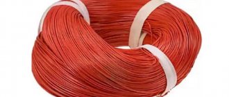
The amount of energy that a conductor transmits depends on a number of factors, the main one of which is the material of the current-carrying conductors. The following non-ferrous metals can be used as the core material of wires and cables:
- Aluminum. Cheap and lightweight conductors, which is their advantage. They are characterized by such negative qualities as low electrical conductivity, a tendency to mechanical damage, high transient electrical resistance of oxidized surfaces;
- Copper. The most popular conductors, which have a high cost compared to other options. However, they are characterized by low electrical and transition resistance at the contacts, fairly high elasticity and strength, and ease of soldering and welding;
- Aluminum copper. Cable products with aluminum cores coated with copper. They are characterized by slightly lower electrical conductivity than their copper counterparts. They are also characterized by lightness, average resistance and relative cheapness.
Various types of cables according to core material
Important! Some methods for determining the cross-section of cables and wires will depend specifically on the material of their conductor component, which directly affects the throughput power and current strength (method for determining the cross-section of conductors by power and current)
Aluminum cable with sector conductors
In such cases, it is necessary to resort to a table where the size (height, width) of the cable takes the corresponding value of the cross-sectional area. Initially, it is necessary to measure the height and width of the required segment with a ruler, after which the required parameter can be calculated by correlating the obtained data.
Table for calculating the area of an electric cable core sector
| Cable type | Sectional area of the segment, mm2 | ||||||||
| S | 35 | 50 | 70 | 95 | 120 | 150 | 185 | 240 | |
| Four-core segment | V | – | 7 | 8,2 | 9,6 | 10,8 | 12 | 13,2 | – |
| w | – | 10 | 12 | 14,1 | 16 | 18 | 18 | – | |
| Three-core segmental stranded, 6(10) | V | 6 | 7 | 9 | 10 | 11 | 12 | 13,2 | 15,2 |
| w | 10 | 12 | 14 | 16 | 18 | 20 | 22 | 25 | |
| Three-core segmental single-wire, 6(10) | V | 5,5 | 6,4 | 7,6 | 9 | 10,1 | 11,3 | 12,5 | 14,4 |
| w | 9,2 | 10,5 | 12,5 | 15 | 16,6 | 18,4 | 20,7 | 23,8 |
Parallel connection of electrical wiring wires
There are hopeless situations when you urgently need to lay wiring, but there is no wire of the required cross-section available. In this case, if there is a wire with a smaller cross-section than necessary, then the wiring can be made from two or more wires, connecting them in parallel. The main thing is that the sum of the sections of each of them is not less than the calculated one.
For example, there are three wires with a cross-section of 2, 3 and 5 mm², but according to calculations, 10 mm² is needed. Connect them all in parallel and the wiring will handle up to 50 amps. Yes, you yourself have repeatedly seen the parallel connection of a large number of thin conductors to transmit large currents. For example, welding uses a current of up to 150 A and in order for the welder to control the electrode, a flexible wire is needed. It is made from hundreds of thin copper wires connected in parallel.
In a car, the battery is also connected to the on-board network using the same flexible stranded wire, since when starting the engine, the starter consumes current from the battery up to 100 A. And when installing and removing the battery, the wires must be taken to the side, that is, the wire must be flexible enough .
The method of increasing the cross-section of an electrical wire by connecting several wires of different diameters in parallel can be used only as a last resort. When laying home electrical wiring, it is permissible to connect in parallel only wires of the same cross-section taken from the same reel.
Sources
- https://electric-220.ru/sechenie-provoda-kabelja-po-diametru-formula-tablica
- https://proprovoda.ru/provodka/provoda-i-kabelya/poperechnoe-sechenie-provodnika.html
- https://www.boncom.by/papers/raschet-secheniya-kabelya
- https://220.guru/electroprovodka/provoda-kabeli/kak-uznat-sechenie.html
[collapse]