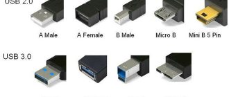
The number of mobile communications devices in active use is constantly growing. Each of them comes with a charger supplied in the kit. However, not all products meet the deadlines set by the manufacturers. The main reasons are the low quality of electrical networks and the devices themselves. They often break down and it is not always possible to quickly purchase a replacement. In such cases, you need a circuit diagram for a phone charger, using which it is quite possible to repair a faulty device or make a new one yourself.
Principle of operation
In the vast majority of cases, mains-powered adapters operate using a pulse circuit. This allows you to obtain lightweight, compact, economical devices. You have to pay for this with complicated circuitry and reduced reliability compared to transformer power supplies.
Most network chargers have the same structure:
- rectifier with filter;
- pulse generator;
- inverter;
- pulse transformer;
- secondary rectifier with filter;
- indication circuits;
- stabilization circuits (may be absent).
The rectifier is often made using a half-wave circuit - the power consumption of the charger is low, so this is sufficient. For the same reason, the capacity of the smoothing capacitor is small. The pulse generator is often circuitously combined with an inverter - the same transistor generates oscillations and switches the winding. But sometimes this unit is also built on a specialized microcircuit. The secondary rectifier is also usually half-wave to avoid unnecessary voltage drop across the diodes. Schottky diodes are used for the same purpose. In most cases, the indication circuits are an LED with a resistor.
Stabilization is carried out using pulse width modulation through feedback. In many schemes, an optocoupler is used to organize it. This ensures galvanic isolation of the output from the high-voltage part.
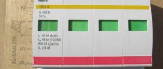
Battery voltage 6 12 24V
Chargers produced today are rarely limited to an exact voltage rating. However, you need to remember that for a car battery, a device with a voltage of 12 V is considered optimal. In addition, stores have chargers for 6 and 24 V. The first is used to recharge motorcycle batteries, the second is suitable for trucks.
On sale you can find devices with switchable modes: 12/24, 6/12/24. The average car owner is unlikely to find the voltage switching option useful, so it is not advisable to pay more for this function.
Charging circuits for mobile phones
Since the process of replenishing the battery with energy is monitored by the phone’s built-in controller, power adapters for mobile phones are made according to a fairly simple scheme. Some of them even have an unstabilized output.
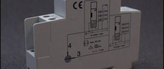
Scheme of an unstabilized network adapter YL-0061.
The mains voltage is rectified by diode VD1 and filtered by capacitor C1. A self-oscillator is assembled on transistor VT1, which “cuts” pulses from a constant voltage that are fed to the primary winding of the pulse transformer TV1. The pulses transformed into the secondary winding are rectified by diode VD5, the voltage is filtered by capacitance C5 and supplied to the consumer. LED VD6 serves to indicate the presence of voltage at the output. Since the output level of this adapter is not stabilized, the voltage will vary depending on the load current.
Circuit diagram of a Chinese network charger with output voltage stabilization.
Another charging circuit for a phone has output voltage stabilization circuits. The input elements, generator, pulse transformer and secondary rectifier are constructed similarly to the previous version. Stabilization is carried out through feedback performed on optocoupler U1. The higher the output voltage, the higher the current through the optocoupler LED, the more the optocoupler receiving transistor opens.
In this way, the bias voltage at the base of transistor VT1 changes and the duration of the generated pulses decreases. When the output level decreases, the reverse process occurs, leading to an increase in the pulse duration.
Car charger circuit diagram.
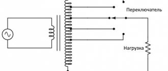
Power supplies designed for charging phones from the car's electrical system are even simpler - they do not have a converter part. They consist of a stabilizer, which is often built according to a linear circuit, and a filter.
How does a battery work?
During operation, a chemical recirculated current source can:
- Power a connected load, such as a light bulb, motor, mobile phone and other devices, using up your supply of electrical energy
- Consume external electricity connected to it, spending it to restore its capacity reserve
In the first case, the battery is discharged, and in the second, it receives a charge. There are many battery designs, but their operating principles are common. Let us examine this issue using the example of nickel-cadmium plates placed in an electrolyte solution.
Low battery
Two electrical circuits operate simultaneously:
- external, attached to the output terminals
- internal
When discharging to a load in an externally applied circuit of wires and, say, a filament, a current flows from a light bulb, formed by the movement of electrons in metals, and in the internal part, anions and cations move through the electrolyte.
Nickel oxides with added graphite form the basis of the positively charged plate, and cadmium sponge is used on the negative electrode.
When the battery is discharged, part of the active oxygen of the nickel oxides moves into the electrolyte and moves to the plate with cadmium, where it oxidizes it, reducing the overall capacity.
Battery charge
The load is most often removed from the output terminals for charging, although in practice the method is used with a connected load, such as on the battery of a moving car or a mobile phone on charge, on which a conversation is taking place. The battery terminals are supplied with voltage from an external source of higher power. It has the appearance of a constant or smoothed, pulsating shape, exceeds the potential difference between the electrodes, and is directed unipolarly with them.
This energy causes current to flow in the internal circuit of the battery in the direction opposite to the discharge, when active oxygen particles are “squeezed out” from the cadmium sponge and return to their original place through the electrolyte. Due to this, the spent capacity is restored.
During charge and discharge, the chemical composition of the plates changes, and the electrolyte serves as a transfer medium for the passage of anions and cations. The intensity of the electric current passing in the internal circuit affects the rate of restoration of the properties of the plates during charging and the speed of discharge. Accelerated processes lead to rapid release of gases and excessive heating, which can deform the structure of the plates and disrupt their mechanical condition.
Too low charging currents significantly lengthen the recovery time of used capacity. With frequent use of a slow charge, sulfation of the plates increases and capacity decreases. Therefore, the load applied to the battery and the power of the charger are always taken into account to create the optimal mode.
How to disassemble a phone charger
Some charger housings are assembled with screws or self-tapping screws. But many inexpensive devices are encased in a shell that is simply glued together.
Cutting the adhesive joint.
If it becomes necessary to disassemble such an adapter, it will have to be cut along the seam. This can be done using a knife or other sharp tool. When cutting the body, it is necessary to take precautions so that the knife does not slip and cause injury. You also need to be careful not to damage the internal contents during the process.
Adapter housing with cover removed.
If you need to reassemble the device after repair, it will have to be glued together. This can be done with dichloroethane or other adhesive. As a last resort, you can wrap the case with insulating tape, sacrificing aesthetics.
Video example of opening the original Samsung ETA-U90E charger.
Types of wireless chargers
Having become familiar with the advantages and disadvantages of chargers that exclude the use of wires, many users have an active desire, despite the high cost, to still become its owner.
Currently, manufacturers are ready to offer several options for such devices, so before making a purchase, it is useful to understand their distinctive features in order to understand which model can rightfully be considered the best.
Popular chargers
The Samsung company, accustomed to surprising consumers with interesting smartphones, has not ignored the issue of creating a wireless charger. The result of the company's work on such a technical problem is the Samsung Wireless Charging Pad.
Many users welcome it because it allows you to charge your smartphone, which can be in any position relative to the top surface of the charger itself.
Samsung Wireless Charging Pad provides charging for smartphones that support not only the WPC standard, but AW4P and PMA.
Another device that is highly popular is the PowerBot. It is welcomed by the consumer because:
- it itself can be connected not only to the mains, but also to a laptop;
- has an acceptable cost;
- accompanied by a high level of reliability;
- The manufacturer guarantees a long operational period.
Another wireless device, Nokia DT-910, provides fast charging for smartphones. In addition, the manufacturer has endowed it with many additional and very useful functions; anyone who owns such a device will be able to understand them.
So, you can easily find and, if desired, purchase a wireless charger of a certain type in the retail network. Since there is no risk to health during further use of such a product, if you have the appropriate amount, you can purchase such a device in order to subsequently allow yourself to expand the possibilities for recharging your smartphone.
Basic faults and repairs
The main malfunctions include problems with the power connector, cord and electronic components. For each type of repair you need to have your own skill level, set of tools and equipment.
How to replace the connector yourself
During operation, the power connectors of the adapters become mechanically loose. The charging process turns into torture or becomes impossible. It is not difficult to replace the connector with your own hands, with a minimum of skills.
| Sequencing | Photo | Important Note |
| 1. First you need to find the same connector. It can be taken from the donor charger. Also, replacing the connector may be necessary if you have a working charger from a similar phone, but with a different connector. | Connector to replace from another adapter. | When installing a connector to another adapter, you need to make sure that the charger and the phone match the supply voltage and the charger can supply the required current. |
| 2. Typically, such connectors on finished chargers have a non-separable design. The unnecessary connector must be cut off with a knife or scissors with a 10-15 cm piece of wire to make it more convenient to work. | A connector cut off from the charger. | |
| 3. The next step is to clean the wires. This is done with a knife or a special insulation stripper. | Stripped wires before connection. | |
| 4. Next, the conductors need to be twisted and the twisted points soldered. Without soldering, the connection strength will be insufficient. | Twisted conductors. | Before connecting conductors, you must ensure correct polarity. Reversing the polarity may damage the phone . |
| 5. Each conductor must be insulated individually. This can be done with insulating tape or heat shrink tubing. | Insulate the joint with electrical tape. | |
| 6. Next, it is advisable to apply general insulation. | Charger ready to use. |
This completes the replacement process and the device is ready for use. You can charge your phone.
If a donor adapter is not available, a suitable connector can be purchased at a specialty store or on the Internet. The old connector must be cut off in the same way, and the new one must be soldered, strictly observing the polarity.
How to repair a charging cable
During operation, the cable conductor may break inside the insulation. The wire breaks due to repeated kinks during use. This usually happens at the outlet of the adapter box or near the connector, but failure is also possible in any other place - it depends on how the device is handled.
You can find the location of the damage using a tester and a needle. One probe of the device is connected to the power connector, and a needle is connected to the second. With its help, the insulation is pierced in different places of the cable and the place where the contact disappears is found.
Finding the fault location in the power cable.
At the break point, the cable must be cut, the wires must be stripped, the conductors soldered and insulated, as in the previous paragraph.
Repairing a broken wire.
Video process of repairing the charging cable.
Simple repair of the charger unit
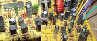
To carry out the simplest repair of a mobile phone charger related to electronic components, you need to have at least a tester, and even better, an oscilloscope. It is convenient if there is a circuit diagram for a specific adapter, but you can do without it. First you need to inspect the board for the presence of charred elements or swollen oxide capacitors.
If everything is visually in order, you can use a tester to check the voltage on the filter capacitor. It is located next to the diode, on the input side from the network.
Elements of the network power supply.
In the example given, the voltage can be measured across two capacitors 1 and 2 - here the input filter is built according to a U-shaped circuit with a choke. The voltage should be approximately the same - at least 220 VDC, depending on the load. If it is significantly less, we can assume a malfunction of the diodes of the high-voltage rectifier 3 , 4 , 5 , 6 (here the full-wave bridge rectifier) or other elements of the input part - resistor 7 or inductor 8 .
If everything is in order, you need to measure the voltage at the output capacitor 9 . It should be approximately equal to the output rating. If the voltage is significantly lower, failure of the secondary rectifier diode 10 . If noticeably higher, feedback optocoupler 11 . If these elements are working properly, you need to check for the presence of pulses at the terminals of the master oscillator transistor 12 . For this you will need an oscilloscope. If there are no pulses, you need to unsolder the transistor and ring it. If it is in order, you need to check the remaining elements of the high side one by one. If everything is OK here, we can assume a break in the windings of the pulse transformer 13 . They need to be tested with a tester - the resistance should be close to zero or no more than a few ohms.
For clarity, we recommend viewing it.
Desulfation function
It happens that due to weather conditions or deep discharge, sulfur sulfates appear on the battery plates, and the electrolyte density decreases along with the capacity. To restore normal parameters, you need to activate the desulfation mode - special charging and discharging cycles. It will ensure the destruction of sulfate elements, cleaning of the plates, and restoration of the capacitance indicator.
In what cases is it better to buy a new adapter?
The main situation when it is better not to try to repair the network adapter, but to purchase a new one, is if it becomes clear that even if functionality is restored, it will not be possible to fully ensure safe operation. If the housing or protective insulation is damaged and accidental contact with live parts is possible.
Of course, it is better to purchase a new device if you are not sure of the final result - you do not have enough qualifications to repair it or there are no spare parts. In general, repairing an adapter for phones is not economically feasible, so it is more rational to buy a new one in any case, unless the fault is clearly expressed (it takes most of the time to find it). And, of course, if it is impossible to buy a new adapter. This applies, for the most part, to old phones - new gadgets are equipped with standard USB type C connectors, and purchasing such a charger (or a separate cord) is not difficult.
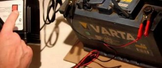
Charging deeply discharged batteries
The worst thing is when the battery is completely discharged. It probably won't be possible to restore it. Most chargers cannot recharge such a battery. They simply don’t see it, they can’t set the operating mode.
There are chargers with an option that allows you to recharge even equipment that is completely discharged. These are pulsed devices that first prepare a deeply discharged battery for a weak current, and then increase the power.
You can also buy a non-automatic charger. By manually adjusting the power of the electric current up or down, you can try to recharge a deeply discharged battery.
Knowing which charger for car batteries to choose, you will purchase equipment that will ensure a quick and efficient supply of electric current to the battery. It is advisable to buy pulse equipment, although it is more expensive than transformer equipment.
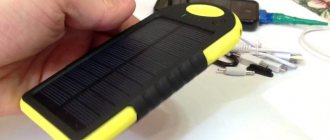
Where can I buy such a portable device?
Most often, a pocket battery can be purchased in online stores ; they always have a high-quality and reliable portable Power Bank device in stock. There are often interesting promotions and offers on store websites; the color and design of products may differ from those shown in the photo. This mobile charger will be an indispensable item for many people who make the most of their smartphones.
Sources
Source - https://radiolub.ru/page/zarjadnoe-ustrojstvo-dlja-mobilnogo-telefona-1 Source - https://radioskot.ru/publ/zu/zarjadnoe_ustrojstvo_dlja_telefona/8-1-0-179 Source - https: //electro-tehnyk.narod.ru/docs/zuSimens.htm Source - https://radiostorage.net/2071-skhema-impulsnogo-stabilizatora-dlya-zaryadki-telefona.html Source - https://www.qrz. ru/schemes/contribute/power/integrations/19.shtml Source - https://zaryad.com.ua/category/24799/ Source - https://hi-news.ru/phone/fakty-kak-rabotaet-ruchnoe -zaryadnoe-ustrojstvo-dlya-telefona.html Source - https://tech.wikireading.ru/4194 Source - https://modelmen.ru/p415/razbiraem-zaryadnoe-ustrojjstvo-ot-mobilnogo-telefona-siemens- Source — https://elektro.guru/elektrooborudovanie/bytovaya-tehnika/drugie-pribory/perenosnye-zaryadki-dlya-mobilnyh-telefonov.html
Materials and tools
List of items that will be needed to create a charger:
- a small base (board) (the remaining components will be attached to it);
- an inductor with high resistance to alternating current should have from 5 to 10 turns (wire diameter is 1 millimeter);
- a film capacitor with a capacity of 0.33 to 1 microfarad;
- two UF type rectifiers;
- soldering iron;
- several field-effect high-voltage transistors that amplify the voltage up to 10 Volts;
- two current converters with rated power dissipation up to 1 Watt;
- solder (material used for soldering and having a melting point lower than the elements being connected).
First, let's see what materials we need to build a homemade wireless charger for a smartphone with our own hands.
Let's start the process
It is recommended for a beginner not to immediately create a device for a modern smartphone model, but to practice on an old device. For example, you can collect a charger for a Nokia push-button phone that was lying around. The algorithm of actions itself is divided into several stages. The first step is to create a transmitter, which will become an independent element, and then you need to move on to developing a receiver installed in a smartphone.
The wireless charger circuit is quite simple. It contains two coils representing a receiver and a transmitter, as well as a resistor and a transistor. If you were able to prepare all the necessary elements described above, then assembling a simple contactless charger will take no more than 60 minutes.
- Let's make a coil.