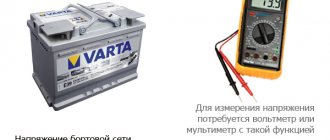
When charging a battery, there are requirements for the voltage and current provided by the power adapter. A situation may arise when its electrical parameters do not correspond to those needed for this procedure. To limit the current, it is necessary to make additions to the circuit used. To do this, you need to understand how the charger works and what physical processes occur during operation.
Battery charging procedure Source avtoshef.com
Why limit
As batteries are used, they gradually discharge. In order to restore functionality, it is necessary to carry out the charging procedure. This ensures the supply of a certain voltage and current. The first of them is usually maintained at a constant level, while the second can be different.
A situation where it is necessary to limit the current may arise in several cases. Most often we are talking about the following options:
- Sometimes the charger is made independently. Moreover, it is designed to use certain parameters. But it is not always possible to make the diagram correctly. Thus, the creator of this block will have to deal with the fact that too much current will pass through the battery.
- When working with smartphones, you regularly have to deal with the need to recharge them. This only takes a few days. Often the charger is connected to a USB cable. In this case, different current strengths are used. We can talk about 1, 0.25, 2 Amperes. Sometimes the required charger is not at hand, and the owner takes one that is designed for a different amperage.
In such situations, the question arises of what will happen if the procedure is carried out without paying attention to the parameters used. Sometimes this can be done painlessly, but in other cases the charger or electrical appliance may be damaged. The result depends on the amount of overcurrent, the device used and the type of battery being charged.
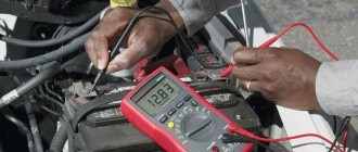
Current limitation when charging the battery Source asterlight.ru
If you find a way by which you can limit the current to the required value, then restoring the battery’s functionality will occur without any difficulties. In order to solve this problem, it is necessary to understand what physical processes occur in the case under consideration and find a way to ensure current limitation.
This video explains how to limit the charger current:
How to increase the current in the generator
The current in the generator directly depends on the load resistance parameter.
The lower this parameter, the higher the current. If I is higher than the nominal parameter, this indicates the presence of an emergency mode - frequency reduction, generator overheating and other problems.
For such cases, protection or disconnection of the device (part of the load) must be provided.
In addition, with increased resistance, the voltage decreases, and U increases at the generator output.
To maintain the parameter at an optimal level, regulation of the excitation current is provided. In this case, an increase in the excitation current leads to an increase in the generator voltage.
The network frequency must be at the same level (constant).
Let's look at an example. In a car generator, it is necessary to increase the current from 80 to 90 Amperes.
To solve this problem, you need to disassemble the generator, separate the winding and solder the lead to it, followed by connecting the diode bridge.
In addition, the diode bridge itself is changed to a part with higher performance.
After this, you need to remove the winding and a piece of insulation in the place where the wire is to be soldered.
If there is a faulty generator, the lead is bitten off from it, after which the legs of the same thickness are built up using copper wire.
After soldering, the joint is insulated with heat shrink.
The next step is to buy an 8-diode bridge. Finding it is a very difficult task, but you have to try.
Before installation, it is advisable to check the product for serviceability (if the part is used, a breakdown of one or more diodes is possible).
After installing the bridge, attach the capacitor, and then a 14.5-volt voltage regulator.
You can purchase a pair of regulators - 14.5 (German) and 14 Volts (domestic).
Now the rivets are drilled out, the legs are unsoldered and the tablets are separated. Next, the tablet is soldered to a domestic regulator, which is fixed with screws.
All that remains is to solder the domestic “pill” to the foreign regulator and assemble the generator.
This is interesting: Operating modes of electric motors
Video description
How to regulate the current in the power supply and other useful information.
If the charging device is homemade, then its author should consider using a current regulator. This will allow you to adjust it to the desired size when using it. Expensive chargers may include this feature by default.
Charging the battery must occur in strict accordance with the rules Source electroadvice.ru
What should be the charging current?
If very strong is used, it may degrade the performance of the charger. In cases where it is too small, charging will occur slowly. It is generally accepted that for car batteries with electrolytes, the optimal current value depends on the capacity, expressed in ampere-hours. It is believed that the maximum permissible current strength is a tenth of this value, and the minimum is a twentieth. An example is a capacity of 60 Ah. In this case, the highest charging current will be 6 A, and the lowest - 3 A.
Charger for car battery Source tj-service.ru
We increase the voltage - all options for solving the problem
Voltage in the on-board network after modification
So, many motorists may decide that the way out of this situation is to install a high-power generator, but at the same time they will have to replace the battery with a more capacitive one. This is done in order not to “kill” the battery that is installed on the car, since a voltage overload will lead to the destruction of the internal cells. This option is not suitable because it is too expensive.
The second option is to install an additional diode from another diode bridge or marked KD202V. This is much cheaper than changing the generator and battery, but you will have to tinker a little. To begin with, it is recommended to study automobile electrical circuits and the operation of the generator, as well as the charging circuit.
Installing the KD202V diode into the generator
When everything is ready, we proceed directly to installing the diode in the generator to increase the voltage in the on-board network. Let's consider the sequence of actions:
- Remove the back cover of the generator.
Remove the back cover from the generator
Wires and diode to increase voltage
Installing heat shrink for male and female wires
Installed heat shrink for the soldered part
We install a voltage regulator with a diode in the generator
We put the back cover on the generator and take out the wires
Electrical diagrams and indicators
To increase the voltage even more, at least to 14 volts, it is necessary to install a diode in circuit D, the voltage regulator. Any diode with a breakdown voltage of 20V and a current of at least 5A is suitable. The voltage drop is preferably no more than 0.6-0.7V. The 2D219B diode is excellent.
| Urev(V) | Ipr(A) | Upr(V) | Irev(mA) | Frame | |
| 2D219A | 15 | 10 | 0.6 (10A) | 20 (15V) | KD-11 |
| 2D219B | 20 | 10 | 0.6 (10A) | 20 (20V) | KD-11 |
| 2D219V | 15 | 10 | 0.45 (10A) | 20 (15V) | KD-11 |
| 2D219G | 20 | 10 | 0.45 (10A) | 20 (20V) | KD-11 |
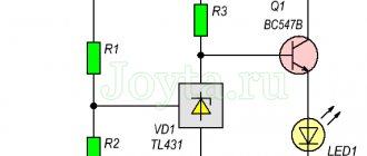
Let's look at the circuit diagrams of diodes:
Manufacturing and installation of a diode in a VAZ-2114 generator
Now that everything is ready, we install an additional diode, more powerful than the previous one. You will need half a meter of wire 2*0.75mm. We solder the ends to the female and male terminals No. 4. We dress them in cambric, or better yet, in heat shrink. By the way, the old one must be removed from the system. Let's take action:
- Now, solder the following circuit to the diode: mother to the cathode, folder to the anode.
Remove the back cover from the generator
Connect the wires going to the diode
Now, everything is ready for the final check and measurements.
Methods for adjusting the output current
When the need arises to reduce the output current, this can be done in various ways. The following describes the most commonly used options for limiting the battery charging current:
- As you know, current and voltage obey Ohm's law. Thus, in order to reduce the current, you need to increase the resistance. One way to do this is to connect a rheostat.
- In some cases, a light bulb is connected to the input of the charger, which reduces the current strength through its electricity consumption.
- If the charger uses a transformer, then its output parameters can be adjusted by reducing the number of turns of the secondary winding. As is known, in rectifiers, alternating current is usually supplied to the primary. It creates a magnetic field, which through the core generates a current of a given value due to the phenomenon of induction. It depends on the number of turns of the winding. The fewer there are, the weaker the current. Next, rectification occurs and a constant voltage is supplied to the output terminals of the charger.
- Fuses or switches open the circuit when the limit value is exceeded. Some of them provide automatic switching on after the electrical parameters meet the standards. Others may have a button installed for this. In this case, the decision to continue working is made by the person.
- Sometimes, at the very beginning of the charging process, a large current may pass through the circuit in the first seconds, which is significantly higher than usual. In this case, thermistors can be used to protect the equipment. The peculiarity of their action is that they change resistance depending on temperature. While the parts are not heated, it is significant. Subsequently, it decreases and moves into the range of normal operating values. This creates reliable protection against inrush current.
- Active loads are circuits using transistors and diodes. They are designed to dynamically limit the current, adjusting to its values at each moment.
- Current-limiting diodes are used for regulation. They can be used for different voltage levels.
When selecting the correct resistance, it is necessary to take into account that which is available in the power supply and internal in the battery. When using the methods described here, you may encounter some difficulties. They can be of different nature.
Using a pulse charger Source stroyvolga.ru
You need to take into account the differences between batteries. Those that are used for mobile gadgets are often used. A small current passes through them. If it is exceeded, it may damage the charger, and in some cases, the gadget. It is important to accurately calculate the amount of additional load.
By watching the video, you can learn how to limit the charger current:
Quenching capacitor instead of resistor
Sometimes the task arises of reducing the alternating voltage of a 220 volt network to a certain specified value, and the use of a step-down transformer (in this case) is not always advisable.
Let's say, a low-frequency step-down transformer, traditionally made on transformer hardware, capable of converting a power of 200 Watts, weighs more than a kilogram, not to mention the high cost.
Therefore, in some cases, it is possible to use a quenching resistor that will limit the current, but in this case, power will be released in the form of heat at the quenching resistor itself, and this is not always acceptable.
For example, if you need to power a 200 Watt lamp to only half its nominal value, you would need to dissipate 100 Watts of power into a quenching resistor, and this is an extremely dubious solution.
A very convenient alternative, for this example, can be the use of a quenching capacitor with a capacity of about 14 microfarads (this can be assembled from three metal film type K73-17, 4.7 microfarads each, designed for 250V, or better yet, 400V) this will allow you to obtain the required current without the need dissipate significant power as heat.
Let's consider the physical side of this solution. As is known, a capacitor connected to an alternating current circuit is a reactive element having capacitance associated with the frequency of the alternating current in the circuit, as well as with its own capacitance.
The greater the capacitance of the capacitor and the higher the frequency of the alternating voltage in the circuit, the greater the current passes through the capacitor, which means the capacitance of the capacitor is inversely proportional to its capacitance, as well as the frequency of the alternating current in the circuit where it is connected.
| This can also be seen from the formula for the capacitance of a capacitor: |
| If a resistor (resistive load) and a capacitor are connected in series to an alternating current circuit, then their total resistance can be found using the formula: |
And because
| So, knowing the voltage at the load, the load current and the voltage at the quenching capacitor, you can determine the capacitance of the quenching capacitor, which must be connected in series with the load to obtain the required power parameters: |
| Consider an example: you need to power a 100-watt incandescent lamp rated at 110 volts from a 220-volt outlet. First of all, let's find the value of the lamp operating current: |
We obtain a lamp current value of 0.91 A. Now we can find the required value of the quenching capacitor capacitance, it will be equal to 15.2 μF.
It should be noted that this calculation is valid for a purely resistive load when the effective value occurs. When using a rectifier, it is necessary to take into account that the effective current value will be slightly less due to the action of ripples. It should also be remembered that polar capacitors should never be used as quenching capacitors.
The best combination of vacuum and solid-state characteristics is a single-ended hybrid audio amplifier.
We do not create illusions, We make the sound alive!
Video description
How to use a light bulb to limit the rectifier current and protect the transformer from short circuit.
When working with car batteries, you can often encounter the use of non-standard chargers. In addition, we must take into account that it can be charged on the go. In all these cases, the current strength can vary within wide limits.
In particular, when recharging while the engine is running, the starting current can be very significant during the first seconds. That is, its strength changes dynamically, so the adjustment must be active, depending on the values of the parameters at this moment.
The principle of battery charging Source ice-people.ru
Charging methods
When charging various computer and home gadgets, direct current is usually directly used. But for car batteries, it is also possible to use alternating current. When charging them, you need to consider the following:
- Using a constant using the selected method ensures the optimal value. As the charge increases, the current will decrease until it drops to zero and the procedure is completed.
- When using alternating current, the battery is charged until the potential difference reaches 14 V. At this point, the current must be halved. After the indicator increases to 15 V, charging is stopped.
In both cases, the initial current must be equal to one tenth of the capacity value, expressed in Ampere * hour.
A block of several batteries Source mysku.ru
Current parameters
Ammeter
A very important quantitative characteristic of current is the current strength (current magnitude), or simply current, a scalar physical quantity equal to the amount of charge that passes through the cross section of the conductor per unit time. But the term “current strength” should not be taken as a manifestation of force in the literal sense
There is no power in the conductors. There is only movement of electric charges
But the term “current strength” should not be taken as a manifestation of force
literally. There is no power in the conductors. There is only the movement of electric charges.
If during time t
Q
flow through a conductor with cross section
S , then the current value is expressed by the formula
I
= Q/ t
The SI unit of current measurement is ampere (A). The current in a conductor is equal to 1 ampere if a charge of 1 coulomb flows through the conductor in 1 second. The current is measured with a device called an ammeter. It is connected in series to the electrical circuit.
For direct current, the same amount of electric charges flows through any cross section per unit time.
A value equal to the ratio of current strength I
to the cross-sectional area of the conductor
S
, is called
the current density
. In the SI system, current density is measured in A/m2. Of course, it is almost impossible to find a conductor with a cross-sectional diameter equal to a square meter. For this reason, current strength is usually measured in A/mm2.
j
= I/S
Any conductor resists the flow of electric charges through it
Therefore, the amount of current in a conductor depends on another important quantity called resistance. This is a physical quantity that characterizes the ability of a conductor to prevent the passage of electric current.
It is denoted by the letter R and is determined by the formula:
R
= U I
,
where U
– voltage, or electrical potential difference, at the ends of the conductor;
I
– the strength of the current flowing between the ends of the conductor.
The SI unit of resistance is the ohm
.
Different materials resist current flow in different ways. Therefore, the resistance of a conductor depends on the material from which it is made, its length and cross-section.
R = ρ ˑ l /S
where ρ
– specific electrical resistance of the conductor, its ability to prevent the passage of electric current;
l – conductor length;
S
- cross-sectional area of the conductor.
Each source of direct electric current creates an external electric field
, which does work to separate positively and negatively charged particles and move them in an electrical circuit.
This work is produced by any forces of non-electrical origin that act inside the source .
These are called
third party forces
. These forces arise for various reasons. For example, in a galvanic cell they appear as a result of chemical reactions, and in direct current generators - when a conductor moves in a magnetic field.
A quantity numerically equal to the work performed by external forces, transferring a unit of positive charge throughout a closed circuit, is called electromotive force
(EMF).
where E
– EMF;
A
is the work done by the source to transfer a charge of magnitude
Q.
The SI unit of EMF is the volt
(
v , V
). The emf of a current source is 1 volt if 1 joule of work is done when moving a charge equal to 1 coulomb.
Transferring an electric charge, the current source does work A on the internal section (within itself) and work A1 on the external section of the electrical circuit. Therefore, total work A = A+ A1
. Dividing both sides of the equation by Q, we get
Quantity A Q
is called
the voltage drop
on the internal section of the circuit (
U
), and
A 1 Q
is called the voltage drop on the external section of the circuit (
U 1
).
A
= U + U 1
, and
U 1 = A –
U. The quantity equal to the product of current and voltage is called power
.
The unit of power is watt
.
P
=IU=I2R=U2R
If there is an EMF source in an electrical circuit, then P
=Iˑε
, Where
ε
– EMF.