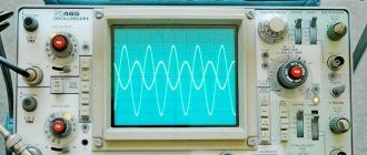
Design and operating principle of an oscilloscope
But regardless of the model and design, the main feature of an oscilloscope that distinguishes it from other measuring instruments is that it allows you to visually observe the shape of an alternating electrical signal in dynamics.
The classic design of an oscilloscope is an indicator on a cathode ray tube. A sawtooth sweep from the built-in generator is supplied to the horizontal deflection system, and the signal being studied is supplied to the vertical deflection system.
If the input signal is periodic, then you can select a horizontal frequency so that it is a multiple of the frequency of the periodic signal. Then it will be possible to observe a stationary picture on the screen, repeating the shape of the input voltage. This operation is called synchronization, and the maximum frequency with which the device can operate is one of its main characteristics.
The DC voltage on the indicator will be displayed as a line at a level depending on the amplitude, and the oscilloscope in this case works like a voltmeter.
For ease of measurement, a calibration grid is applied to the indicator glass with a vertical unit of measurement (Y) of amplitude in volts, and a horizontal unit (X) of duration (period) in ms/μs as the reciprocal of frequency. The relationship between the period of oscillations and their frequency is described by the formulas f = 1/t and t=1/f, where f is the frequency and t is the duration. A period of 1 ms (ms) corresponds to a frequency of 1 kHz, and 1 μs (µs) corresponds to 1 MHz.
Types of scans
In different operating modes of the oscilloscope, linear (created by a sawtooth voltage) sweeps may differ:
- One-time. The generator starts once, then locks out. This sweep is needed to capture non-repeating signals.
- Waiting. The launch occurs immediately after the signal. Needed to monitor rare fluctuations.
- Self-oscillatory. The generator turns on periodically when there is no signal. Convenient for displaying frequent periodic pulses.
An oscilloscope examines various types of signals. They can be constant (mains voltage), periodic (noise, interference, sounds, etc.). Periodic ones can occur randomly or at regular intervals. Depending on how often or rarely the signal occurs, one or another operating mode is selected. Most often, an oscilloscope has two modes: automatic (self-oscillating) and standby. It could also be one-time.
Selecting the oscilloscope operating mode
If we do not know how often the impulses occur, we usually choose the automatic mode. In it, even if there is no potential at the input or if its level is insufficient, the screen lights up. The “zero” signal is displayed - a straight line that should go along the horizontal axis on the screen (set along the line using the arrow controls). When potential appears at the input, it is displayed on the screen. The picture is periodically updated and we see the signal unfolding over time.
Operating mode
Standby mode is good for signals that rarely appear. While there is nothing at the input, the screen does not light up. When any changes occur, it lights up, the sweep generator starts and the signal is displayed on the screen. Triggering can be configured either on the rising edge of the pulse/sine wave or on the descending edge. You can configure the trigger not for the signal being studied, but for the event that precedes it (if there is one).
Single mode configures the oscilloscope to accept a single signal. When the potential of the required level arrives at the input, the signal is displayed on the screen. After this, the device goes into an inactive state. And, even if there is the next potential at the input (or five, or one hundred and five), it will not register it. To receive another pulse, you need to “cock” the device again.
Connecting the device
To connect the oscilloscope to the electrical circuit under study, the device is equipped with a coaxial cable with a probe containing a “ground” terminal. Typically equipped with an alligator clip. And also a signal wire (“phase”), usually with a needle contact that allows you to plug into a small contact pad.
The probes can be replaceable. In addition to standard ones, attenuator probes containing an additional high-resistance resistor are popular. It is needed to attenuate the input signal and expand the ability to measure high voltages without the risk of burning the input amplifier.
Controlling and setting up the oscilloscope
For the vast majority of models, the settings are organized in such a way that one group sets the amplitude modes, and the second controls the sweep.
The largest and most visible amplitude control is the Y-axis signal scale control, labeled “V/div”. Its function is to set the scale so that the image fits the screen size.
For example, to measure signals with an amplitude of 30V, you need to set the scale to 10V per division, then the signal on the screen will reach 3 divisions. Structurally, the adjustment is made in the form of a rotating handle with stepwise switching. There is a line indicating the value selected from those located around the handle.
Usually there is an additional smooth adjustment handle, combined with the main one. The second most important control is the vertical shift knob, which moves the signal image up and down vertically. This is necessary both for calibrating the device and for more accurate amplitude measurement. Offset allows you to use the entire screen for measurement and align the signal with the grid lines.
Any oscilloscope also has a toggle switch for switching from direct input to capacitive (via a capacitor). Using the latter allows you to cut off the constant component and work only with the variable component of the signal. Which is very useful, for example, when assessing the noise level of a power supply.
In the sweep control group, the central element is the sweep speed switch, labeled “Time/div.” Structurally, it is similar to the signal scale switch, with step switching and smooth adjustment knobs. This switch sets the value in ms or µs per division in accordance with the frequency of the signal being studied so that one or more periods are placed on the screen.
There is always a handle for horizontal beam shift, usually marked with right-left arrows. Using this handle, you can bring the area of interest under the grid lines for a more accurate measurement.
All oscilloscope models have the ability to use an external sweep source instead of an internal generator. It is with its help that Lissajous figures are obtained on the screen, from which you can see the relationship between the frequencies and phases of two sisusoids. The input for external sweep is labeled “Input X” and is located in the sweep control group.
A separate group consists of synchronization settings. It includes an internal-external sync switch, an external sync input, and a fine adjustment knob.
In addition, there are technical controls:
- device on/off button;
- adjusting the brightness and focusing of the cathode ray tube beam;
- turning on the screen scale backlight.
What are they?
After we have found out why an analog and any other oscilloscope is needed, we can move on to its classification. There are 6 main types of measuring instruments:
- Analog. They are considered classic models of measuring devices. An analog oscilloscope is an instrument for measuring average signals. The lower frequency limit is 10 Hz. The price of such equipment is much lower than digital equipment, which is why it is still popular among novice electronics engineers. The main advantage of analog models is the least distortion of the observed signal. Otherwise, they are much inferior to digital technology. Main components of the device: a. input signal divider; b. scheme of synchronization and deviation of the horizontal plane; c. ray tube; d. power unit.
- Digital storage. The devices offer more research and measurement capabilities, so their price is much higher than analog models. Analyzing abilities are the main advantage of storage devices. By setting certain settings, you can force the equipment to record data in digital format immediately after normalization. The signal data image is more stable, and the user can edit the final result by marking or scaling. Examples of digital storage oscilloscopes: TBS1052B Tektronix, TBS1152B-EDU Tektronix, R&S RTC1000. Main components of the device: a. input signal divider; b. normalization amplifier; c. ADC converter; d. information output and input devices; e. Memory device.
- Digital phosphors. Devices of this type operate on a digital phosphor and are considered the most expensive among all types of oscilloscopes. They are able to simulate changes in the intensity of the output data. This feature simplifies the diagnosis of abnormalities in pulse blocks. Examples of phosphor oscilloscopes: Tektronix MSO DPO2000B, Tektronix DPO70804C, Tektronix DPO72304SX.
- Digital stroboscopic. These models use a sequential signal gating effect. They are used to analyze high-frequency repetitive signals whose frequency exceeds the sampling frequency of the device. They sample multiple signal points over several successive periods and then recreate the original waveform. The operating frequency of this type of equipment exceeds 50 Hz. One of the popular models of sampling oscilloscopes is the Tektronix DSA8300. A distinctive feature of the device is a wide selection of optical and electrical modules for testing.
- Portable. Measurement technology is developing rapidly, so compact equipment has become available for conducting signal studies. The advantage of such devices is their low power consumption and small size. Electronics engineers often use portable equipment in their work. Examples of small measuring technology: R&S RTH Scope Rider series, R&S (HAMEG) HMO Compact series.
- Combined. These devices have built-in spectrum analyzers, so they are able to not only collect information about the incoming signal, but also determine the number of harmonics along with the level. Examples of combined equipment: MDO3024 Tektronix, MDO3104 Tektronix, MDO4054C Tektronix.
It will be interesting➡ Vector diagram of currents and voltages
Oscilloscopes are indispensable when measuring the time and amplitude parameters of an electrical signal. Modern device models are also capable of performing spectral analysis.
Kinds
Digital models have recording and archiving functions, which expands the possibilities. To compare results online, devices with several channels are used. There are copies connected to a PC and combinations with other measuring devices.
The choice of analog models (except for simple and educational ones) implies knowledge of a variety of settings, the adjustment is complicated. On the other hand, such devices provide in-depth practice.
Digital models are the recommended choice and will allow you to quickly learn the basics. These are computing systems, with them data acquisition and interpretation are easier and much faster. There are also analog-digital models.
Signal measurement
The procedure for measuring the parameters of a periodic signal is as follows:
- The ground clamp is fixed on the common wire of the circuit, and the signal probe is connected to the controlled location of the circuit where readings will be taken.
- Using the slider, we set the vertical scale so that useful information fits entirely on the screen and occupies most of it.
- Using the frequency regulator, we ensure that several periods of the signal fit on the screen.
- By finely adjusting the frequency, we achieve a stable image so that the picture does not float.
- Now that a stable image is installed on the screen, you can determine its shape, amplitude and period using the on-screen scale.
- For more precise measurements, you can use the vertical and horizontal offset knobs to bring the image elements of interest under the crosshairs of the grid lines.
In order to be confident in the accuracy of the readings, you must comply with several simple requirements:
- after turning on the CRT oscilloscope, you need to let it warm up for 10-15 minutes;
- After each switching on, the device must be calibrated. Most models have a built-in calibration generator that produces a square wave signal with a fixed amplitude and frequency;
- the device must be grounded;
- a signal with a very low frequency (up to 10 Hz) when connected via a capacitive input is highly distorted. Working in this mode is not recommended.
The best way to learn is through hands-on work. Having acquired the first skills of working with a simple analog oscilloscope, in the future you can move on to more complex devices. Which will have additional functions and advanced capabilities. The main thing is to have a desire and interest in electronic technology.
Features of digital models
A digital oscilloscope works differently - the analog signal is converted into digital form. In this form, it is recorded in memory and transmitted to the monitor, where it is converted from digital format back into analog form. Display on the screen begins only at the moment when the input level exceeds a certain value (set by settings).
The frequency of changing the picture depends on the selected operating mode: automatic, single and normal. Normal is the equivalent of waiting.
Simplified block diagram of a digital oscilloscope
Why are digital models better? Firstly, this conversion makes the image more stable. Secondly, it's easier to zoom in and out. Thirdly, there is a recording option. Well, and the dimensions. The smallest analog oscilloscope, S1-94, has dimensions of 100*190*300 mm and a weight of 3.5 kg. And digital ones with dimensions of 100*50-60*13-20 mm have a weight of about 150-300 grams. And this includes batteries.