Basics of measurements for beginner radio amateurs and those who have started working in radio electronics, what is measurement accuracy, DC voltage measurement and other useful knowledge. When repairing or setting up electronic equipment, it is impossible to do without measuring current, voltage, resistance, as well as other electrical quantities on which the operation of the circuit depends.
Measurement accuracy
It is impossible to measure an electrical quantity, or any quantity in general, with absolute accuracy.
There is always an error, depending both on the measuring device itself and on the person conducting the measurement. For example, the accuracy of a measurement strongly depends on the correct choice of the measurement limit. Let's say there is a voltage of 2.9875V in some circuit.
If you use a multimeter, in order to get the most accurate measurement result, you need, in this case, to select the “20V” limit. At this limit, the multimeter will show “2.98V”. If you select the limit “200V”, the device will display “2.9V”.
Measuring instruments are divided into seven accuracy classes: 0.1; 0.2; 0.5; 1.0; 1.5; 2.5; 4.0 (except for special cases when ultra-precise measurements are required).
These numbers show what error the device allows, as a percentage of the selected measurement limit. Inexpensive devices, such as the M-838 multimeter, usually do not give an error less than class 1.0.
Thus, if your multimeter corresponds to an accuracy class of 1.0, then at the “20V” limit it can err by no more than 0.2V (20/100 * 1.0=0.2).
In addition to the accuracy class of the device and the correct choice of the measurement limit, the measurement result is also influenced by such an indicator as the internal (or input) resistance. But more on that later.
DC voltage measurement
When measuring voltage, a voltmeter or multimeter, previously switched to measure direct voltage (DCV), is connected in parallel with the source of the voltage to be measured. Suppose you need to measure the voltage across resistor R2 (Fig. 1). To do this, we connect the multimeter M in parallel with resistor R2.
The multimeter shows the polarity of the measured DC voltage relative to its “COM” socket. That is, in the diagram in Fig. 1, the probe coming from the “COM” socket is connected to the minus of the measured voltage, and the second probe (V) is connected to the plus. Thus, the voltage on the V probe relative to the COM probe is positive.
Rice. 1. Experimental design.
If the probes are swapped or the “battery” G1 is turned over, the voltage on the V probe relative to the COM probe will be negative, and a “-” icon will appear on the multimeter display before the measurement result number. As you can see, to measure voltage you need to know two points between which there is the desired voltage.
When they say that you need to measure the voltage on a resistor, capacitor or some other object that has two terminals, everything is clear - we connect one probe to one terminal, and the second to the other. But what if you need to measure the voltage at point “A”, or at the collector VT1 (Fig. 2)?
Here you should know that if it is not stated anywhere regarding what the voltage should be measured at a given point, it is always measured relative to the common wire. Thus, we connect the “COM” probe of the multimeter to the common wire of the circuit, and the second probe to the point at which the voltage needs to be measured, in this case to the VT1 collector (Fig. 2).
Rice. 2. Connect a voltmeter to measure the voltage at the transistor collector relative to the common one.
If it is said that the voltage on the collector of VT1 needs to be measured relative to its emitter, then the device must be connected, respectively, between the emitter and the collector of the transistor (Fig. 3).
Rice. 3. Measuring the voltage at the collector of the transistor relative to the emitter.
Therefore, before you start measuring voltages in the circuit, you need to understand what to do. And connect the “COM” of the multimeter to the very place relative to which you want to measure the voltage.
Any voltmeter has some internal resistance, which in certain cases can have a very significant effect on the measurement result.
It may even be that if you connect a voltmeter with an insufficiently large internal (input) resistance, the circuit will stop working altogether.
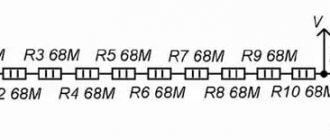
To understand why the input resistance of a voltmeter should be as high as possible, let's look at Figure 4. Suppose there is a voltage divider across two identical resistors of 100 kOhm each. This means that the voltage across resistor R2 (U2), according to the formula: U1/U2=(R1+R2)/R2, will be equal to half the voltage of the power source G1 (U1), that is, 4.5V.
Rice. 4. Scheme of the experiment with the resistance of a voltmeter.
Now let's see what happens if you connect a voltmeter to R2, whose internal (input) resistance (RV) is, say, 10 kOhm. The internal resistance of the voltmeter RV will be connected in parallel with resistor R2 (it will bypass it).
As a result, the actual resistance R between the minus of the power supply G1 and the connection point R1 and R2 will drop to a value determined by the formula: R=(R2*RV)/(R2+RV), and will no longer be 100 kOhm, but only about 9.09 kOhm
Now, according to the formula U1/U2=(R1+R)/R, the voltage on R2, with a voltmeter with an internal resistance of 10 kOhm connected to R2, will be about 0.749V.
And this voltage will be shown by a voltmeter, instead of the required 4.5V! If the internal resistance of the voltmeter is significantly greater than R2, for example, 1000 kOhm (1 Megaohm), the measurement result will be closer to the real one:
R= (100*1000)/(100+1000) = 90.9 kOhm.
U2= 9 /((100+90.9)/90.9) = 4.286V.
As you can see, the higher the internal (input) resistance of the voltmeter in relation to the internal resistance of the source (or circuit element) on which the voltage needs to be measured, the more reliable the readings of the device will be.
In technical documentation, the input resistance of voltmeters (or universal devices when measuring voltage) is usually indicated in Ohm/V.
This means that in order to find out the actual input resistance of the device at a certain measurement limit, you need to multiply the specified resistance by the selected measurement limit.
Let's say the multimeter's data sheet indicates the input resistance is 300 kOhm/V. This means that if the multimeter is switched, for example, to the “20V” limit, its input resistance will be six megaohms (300 kOhm * 20V = 6000 kOhm).
Security measures
When dealing with electricity in any way, it is important to take the following precautions:
- You cannot measure the voltage in a faulty outlet; it is also prohibited to use damaged devices, especially if the problem is insulation;
- Do not touch the metal parts of the probes with bare hands - only with rubber gloves;
It is important to follow safety rules when working
- When setting a probable value, it is necessary to set a larger value, for example, not 200 V, but 300 V. If the value is higher than the set value, the device will simply burn out;
- Metal parts should not touch when measuring, otherwise a short circuit will occur;
- When working with voltages above 60 V, it is strongly recommended not to hold the probes in different hands. Otherwise, when struck, the current will pass along the “line of death” - hand-heart-hand;
- Before starting work, you need to check the device itself: is the case intact, are the screws tightly tightened, are the cable connections secure;
- It is extremely important to follow safety precautions and read the instructions for the multimeter in advance.
You may be interested in this Features of crimping tools
It may be necessary to measure DC voltage for various jobs. This can be done using special devices: a simpler voltmeter and tester or a universal multimeter. When working, you must follow safety precautions, and if in doubt, contact a specialist.
AC voltage measurement
Almost everything said above about measuring DC voltage remains valid when measuring AC voltage. But there are also significant differences.
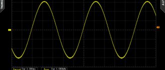
For example, the accuracy of an AC voltage measurement is highly dependent on the frequency of the AC voltage being measured.
Most multimeters are calibrated for 50 Hz (or 60 Hz) AC voltage, so when measuring higher voltages, such as audio frequencies, their readings may vary significantly.
The data sheets of some multimeters indicate the error when measuring at different frequencies, for example, 50 Hz and 1000 Hz or 50 Hz, 1000 Hz and 10000 Hz.
Another interesting detail is that some devices, in the AC voltage measurement mode, do not react in any way to DC voltage, while others, when there is DC voltage in the measured circuit, show some erroneous numbers.
For example, if an M-838 multimeter switched to measure alternating voltage (ACV) is connected to a constant voltage source, it will show a number that is approximately one and a half times the direct voltage of this source. But the more expensive multimeter, DT9206, does not react in any way when measuring alternating voltage to direct voltage (shows zeros).
The fact is that some devices, such as the DT9206, have a decoupling capacitor, which, when measuring alternating voltage, is switched on at the input of the device and does not allow direct voltage to pass through to its circuit. The M-838 does not have such a capacitor.
You definitely need to know this when you measure AC voltage in a circuit where there is a DC component. Figure 5 shows a diagram of the output part of the amplifier stage. Please note that at the collector of the transistor there is a constant voltage of 50V and an alternating voltage of 20V.
To measure alternating voltage with a device such as the M-838 (without an input coupling capacitor), it must be connected through a capacitor (Cx). But a device like DT9206 can be connected directly; the DC component does not affect its readings.
Rice. 5. Diagram of the output part of the amplifier stage.
Model overview
There are a large number of different multimeters on the market - from cheap home ones to expensive professional ones. The choice of a specific model depends on the needs of the buyer and the problems that he wants to solve.
Important! Before purchasing, you should study reviews and reviews: they will allow you to find out the shortcomings of specific models and avoid them.
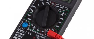
DT-830B
A multifunctional device made in China that is convenient to take with you. It has small dimensions (12.6*7*2.8 cm) and weight (less than 150 grams). Functions as an ammeter, ohmmeter and voltmeter, mainly used to measure voltage, DC current and resistance, and test transistors and diodes. The information is reflected on the display.
The device is highly sensitive and has a small, no more than 1%, error. Its average cost is about 200-300 rubles.
"DT-830B" - inexpensive but high-quality tester
Users rate the tester positively: the tool does its job well and is well suited for home use. It is especially noted that it can even test batteries, since it measures current up to 10 Amperes.
Among the shortcomings, they most often point to a weak, thin probe that requires rework.
C266 (DT-266)
A small and easy-to-use device that allows you to measure alternating and direct current and voltage, circuit resistance and its integrity, as well as temperature (from 0 to +750 degrees). The model has a high degree of protection, overload and charge indicators, the kit includes probes, a thermocouple and a case. The measurement results are stored in memory. The average cost is 600-700 rubles.
"DT-266" - high-precision device
Buyers note the high accuracy of measurements, low price and good quality of the device, ease of use. The disadvantages include low-quality probes - they quickly fail.
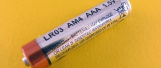
One of the best options for home. The model is small and light (less than 100 grams), fits in a pocket or tool box. Allows you to measure direct and alternating voltage, direct current and resistance, make a “ringing”, measure temperature from −10 to +50 degrees. The kit includes only the probes. The average price is about 300 rubles.
"M812" is well suited for home work
Reviews about the model are mostly unanimous: the device is nothing special, but it does a good job of doing a little work and fully justifies the low price. Some also note the low accuracy of the readings, although other buyers report good data accuracy.
DT9208A
An inexpensive but accurate device allows you to measure the characteristics of the electrical network: voltage, current, frequency, resistance and others. The data is displayed on the screen. Thanks to the ability to obtain accurate data and high-quality assembly, the device is suitable for both amateurs and professionals. The kit includes a set of probes and a thermocouple for measuring temperature. The average cost of a set is 900 rubles.
Buyers rate “DT9208A” low
Unfortunately, users note that the device has a large number of shortcomings: low quality probes and a weak body, weak response, and the tester also “sins” with inaccurate measurements.
Current measurement
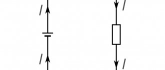
To measure current (or simply, measure current), an ammeter (or a combined device that measures current) is connected in series to the electrical circuit (Fig. 6). In other words, into an open circuit, so that all the current, the strength of which needs to be measured, flows through the device.
In Fig. Figure 6 shows how the device is turned on when measuring current consumption by the amplifier stage, and Figure 7 shows the collector current of the transistor.
Rice. 6. Turn on the ammeter when measuring current consumption by the amplifier stage.
The current measurement result is influenced by the resistance of the measuring device. But this effect is the opposite of what a voltmeter has on the measured voltage. The ammeter is connected to the circuit in series, and its resistance is added to the resistance of the circuit.
The total resistance of the circuit increases and the current decreases. Therefore, the resistance of the device measuring current should be minimal. When measuring the current, switch the multimeter to the “DCA” position.
When measuring weak currents, the probes of the device are installed in the same sockets as when measuring voltage. To measure current more than 200mA (0.2A), up to 10A, multimeters have an additional socket with a fuse.
Rice. 7. Measuring the collector current of the transistor.
A serious disadvantage of directly measuring current is that to connect the device you need to make an open circuit. This is especially inconvenient when measuring large and very large currents.
Therefore, to measure large currents, devices with so-called “current clamps” are used, which are a current sensor that determines the current strength by the magnetic field created by the current.
Externally, current clamps really look like clamps or a clothespin, which is put on a conductor with a measured current. Another advantage of current clamps is that the measuring device is completely isolated from the circuit being measured.