Accuracy class
During laboratory measurements, it is necessary to know the accuracy of the measuring instruments, which in turn have certain characteristics and differ in design. Each of the measuring instruments (MI) has certain inaccuracies, which are divided into basic and additional. Situations often arise when it is not possible or simply not required to make a detailed calculation. Each measuring instrument is assigned a certain accuracy class, knowing which, you can find out its range of deviations.
Normalized error values will help you find out the errors of the measuring instrument in a timely manner. This definition should be understood as the limiting indicators for a measuring instrument. They can be different in size and depend on different conditions, but they should not be neglected in any case, because this can lead to a serious mistake in the future. The normalized values should be less than what the device shows. The limits of permissible error values and the necessary coefficients are entered in the passport of each dimensional measuring device. You can find out detailed standardization values for any device using the corresponding GOST.
Instrumentation systems. Accuracy classes.
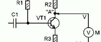
14.1.1. Electrical measuring instruments are technical means that produce signals of measuring information in a form accessible to direct perception by an observer.
. According to the type of quantity being measured, electrical measuring instruments are divided into the following types:
voltmeters (indicated by the letter V
);
14.1.3. According to the physical principle of operation, the following systems of electrical measuring instruments are distinguished:
a) magnetoelectric; b) electromagnetic; c) electrodynamic; d) induction; and etc.
14.1.4. Electrical measuring instruments are classified according to the accuracy class The accuracy class is indicated by a number that is equal to the reduced error (in percent) allowed by the device. They produce devices of the following accuracy classes: 0.05; 0.1; 0.2; 0.5; 1.0; 1.5; 2.5; 4.0. In electricity meters, the accuracy classes are as follows: 0.5; 1.0; 2.0; 2.5.
14.1.8. For most indicating electrical measuring instruments, the moving part of the device moves due to the action of torque. Torque results from the interaction of magnetic or electric fields and is to some extent proportional to the quantity being measured. There is always a counteracting moment in a measuring device, which is created by mechanical or electromagnetic force.
14.2.1. In devices of a magnetoelectric system, torque is created as a result of the interaction of a permanent magnet with a current-carrying conductor. The moving part can be a current-carrying frame or a permanent magnet located on an axis.
Magnetoelectric devices are used to measure direct currents and voltages . They can also be used to measure resistances like galvanometers.
The disadvantages of the devices of this system can be considered their unsuitability for operation in alternating current circuits, sensitivity to overloads and dependence on ambient temperature.
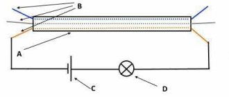
14.2.2. The electrical measuring device of the electromagnetic system has a fixed coil and a ferromagnetic plate located on the axis. If a measured current flows in the coil, the field created by the coil draws the ferromagnetic lobe deeper.
The direction of the arrow deflection does not depend on the direction of the current, i.e., instruments of the electromagnetic system can measure both in direct and alternating current circuits.
14.2..3. Electrodynamic system devices have a measuring mechanism consisting of two coils: fixed and movable. The fixed coil has two sections, inside of which there is a moving coil located on an axis. In the presence of current in the coils, electromagnetic interaction forces arise, tending to rotate the moving coil, i.e. the torque is proportional (for direct currents and the corresponding design of the mechanism) to the product of the currents:
The accuracy class of measuring instruments is a characteristic determined by the limits of permissible main (we measure according to the conditions of the passport) and additional (conditions deviate from the passport) errors. Accuracy class K =
, — absolute error, — normalized value or upper limit of measurement.
Source
What is the accuracy class of the device?
An accuracy class is a characteristic of a device, which is determined by the limits of the permissible main and additional errors, as well as other properties provided for by the standards for this type of product that affect the accuracy. This parameter is present in the technical characteristics of many devices that have reference output parameters, be they electronic or mechanical measuring devices. The accuracy class is the main characteristic of measuring equipment: scales, multimeters, oscilloscopes, instrumentation equipment and others. The higher this value for a device, the more such a device costs, this is due to the complexity of producing such products.
Normalized error
Types of marking
The accuracy classes of absolutely all measuring instruments are subject to marking on the scale of these same instruments in the form of a number. Arabic numerals are used to indicate the percentage of normalized error. The designation of the accuracy class in a circle, for example the number 1.0, indicates that the error in the device’s needle readings will be equal to 1%.
If the designation uses a tick in addition to the number, this means that the scale length is used as a normalizing value.
Latin letters for designation are used if it is determined by the limits of absolute error.
There are devices on the scales of which there is no information about the accuracy class. In such cases, the absolute should be equated to one half of the smallest division.
Nature of errors and accuracy class designations
The nature of errors is associated with many limitations that humans cannot yet overcome. The latter is associated with the materials used, with the various forces that act on the measurement element. That is why in metrology and instrument making it was decided to introduce the concept of instrument accuracy class. Several approaches are used for standardization:
- normalization based on measurement results;
- normalization at the upper limit of the scale.
For pointer-type measuring instruments, the accuracy class is indicated as a number. This number shows the maximum possible deviation percentage. For example, for a voltmeter that operates in the range 0-30 V with an accuracy class of 1.0, the error will be no more than 0.3 V. In some cases, CT is indicated by a number with the letter s. In this case, half the division is taken from the minimum division value. Quite often, this characteristic is used to designate elements that do not have a scale, for example, current transformers.
Limits
As mentioned earlier, the measuring device, thanks to standardization, already contains random and systematic errors. But it is worth remembering that they depend on the measurement method, conditions and other factors. In order for the value of the quantity to be measured to be 99% accurate, the measuring instrument must have minimal inaccuracy. The relative one should be about a third or a quarter less than the measurement error.
A Question of Choice
To install an electric meter in a private house or apartment, models that have a class of at least 2 are suitable.
In addition, when going to the store to buy an electric meter, you should know exactly the following characteristics:
- Phase of the electrical network. If the electrical network connected to the meter is single-phase, then the device must also be for a single-phase network. A three-phase electric meter can also be installed to track electricity usage, but such devices tend to be more expensive. When the meter is installed to measure three-phase current, the corresponding inscription must be indicated on it. Single-phase devices are not used to calculate three-phase current.
- The load under which this device will be operated. Depending on the maximum load that will be connected to the electricity metering device, a model is selected, on the body of which this indicator is indicated. For a standard load used in a private home, electric meter models designed for a maximum current of 60 A are used. If you plan to connect powerful electric heating boilers, then an electric meter is selected with an indicator of at least 100 A.
- If the electricity supplier can sell electricity at 2 tariffs, then the tariff of the meter is also taken into account when purchasing. Two-tariff devices allow you to save significantly on electricity bills. When using electricity at night, such a meter will record consumption separately. If the electricity supplier allows such payment, then installing a multi-tariff meter will allow you to use electricity more efficiently.
- Mounting method. Allows you to install the device in an existing box, or in place of a device that was previously installed.
Selecting an ammeter based on metrological characteristics
The most common source of error when measuring current is that the ammeter has a non-zero input resistance. The voltage generated across the meter causes the voltage across the device under test to decrease. If the reduction is significant, it will result in significantly less current flowing. In other words, the meter does not show the current that is actually flowing in the network.
In order to minimize this error as much as possible, two main types of measurement architecture are used: shunt ammeters and feedback ones.
The error caused by a shunt meter, expressed as the ammeter's partial voltage divided by the output resistance.
Ammeters with feedback are closer to “ideal”. It produces voltage in the feedback path of the high gain op amp. This voltage is also proportional to the measured current, but does not appear at the input of the device. As a result, sensitive closed-loop meters such as electrometers and picoammeters have a voltage load typically limited to 200 µV.
For industrial measurements, analog panel-type ammeters are most often used. When choosing them, you should consider the following points:
2/3 of the maximum scale.
Important! Internal resistance is a determining value when choosing a meter. It should be taken according to the magnitude of the measured impedance, otherwise it will lead to large measurement errors. Since internal resistance reflects the power consumption of the meter itself, when measuring current, a device with internal resistance should be selected as low as possible.
ERRORS AND ACCURACY CLASSES OF ELECTRICAL INSTRUMENTS
ERRORS AND ACCURACY CLASSES OF ELECTRICAL INSTRUMENTS
The value measured by a device always differs from the true value by a certain number, called the device error. The errors of measuring instruments are determined by verification, i.e., by comparing the readings of the device being verified with the readings of a more accurate, standard device when they measure the same value. The value of the measured quantity, determined using a reference device, is considered to be valid. However, the actual value differs from the true one by the error inherent in this reference device. There are absolute, relative and reduced measurement errors.
Types of ammeter errors
To understand the size of the measurement error, you need to compare the results obtained with the reference ones.
In metrology, several types of errors are used for all electrical meters, both ammeters and voltmeters: absolute, relative and reduced.
The absolute error of an ammeter is the difference Δ between the measurement result obtained on the instrument scale (Xi) and the actual value of the current in the circuit (Xd). The absolute error of an ammeter is described by a simple formula and is expressed in units of current A.
- Δx - delta X
- Xd is the actual reading of the current strength received by the reference device;
- Xi is the measured value on the instrument scale.
Relative error (δ) is the ratio of the absolute error of the ammeter Δx to the actual current reading taken from a standard device. It can be indicated as a percentage, then the quotient is multiplied by 100, or expressed in relative units.
The reduced error is the value reduced to the measurement range of the ammeter, which is equal to its scale. It is obtained as a quotient of the absolute error Δх and the normalized value (Xн), in values corresponding to the absolute error Δх multiplied by 100%:
How to determine the accuracy class of an electrical measuring instrument, calculation formulas
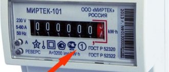
To determine the accuracy class, you need to look at its case or user manual, in it you can see a number circled, for example , ① this means that your device measures a value with a relative error of ±1%.
But what to do if the relative error is known and it is necessary to calculate the accuracy class of, for example, an ammeter, voltmeter, etc. Let's look at the example of an ammeter: known ∆x=basic (absolute) error 0.025 (see instructions), number of divisions x=12
We find the relative error:
Y= 100×0.025/12=0.208 or 2.08%
( conclusion: accuracy class – 2.5).
It should be noted that the error is uneven over the entire scale range; by measuring a small value you can get the greatest inaccuracy and as the desired value increases, it decreases; for example, consider the following option:
Voltmeter with class p=±2, upper limit of device readings Xn=80V, number of divisions x=12
Absolute permissible error limit:
Relative error of one division:
If you need to perform a more detailed calculation, see GOST 8.401-80 clause 3.2.6.
Verification of devices, why it is needed
All measuring instruments measure with a certain error; the accuracy class only indicates the range in which it lies. There are times when the range of error imperceptibly increases, and we begin to notice that the meter “simply” begins to lie. In such cases, verification helps.
This is the process of measuring a reference quantity under ideal conditions with an instrument, usually carried out by a metrological service or in the metrological department of the manufacturer's enterprise.
There is a primary and periodic inspection , the initial inspection is carried out after the product is released and a certificate is issued, the periodic inspection is carried out at least once a year, more often for critical devices.
Therefore, if you doubt the correct operation of the device, you should have it checked at the nearest metrological service, because the meter can lie both to a lesser and more extent.
how to easily check the electricity consumption in an apartment in our article.
Rationing
Accuracy classes of measuring instruments tell us information about the accuracy of such instruments, but at the same time it does not show the accuracy of the measurement performed using this measuring device. In order to identify in advance the error in the instrument readings, which it will indicate during measurement, people normalize the errors. To do this, they use already known normalized values.
Rationing is carried out according to:
- absolute;
- relative;
- given.
Formulas for calculating absolute error according to GOST 8.401
Each device from a specific group of devices for measuring dimensions has a certain value of inaccuracies. It may differ slightly from the established standardized indicator, but not exceed the general indicators. Each such unit has a passport in which the minimum and maximum error values are recorded, as well as coefficients that have an impact in certain situations.
Download GOST 8.401-80
All methods of standardizing measuring instruments and designating their accuracy classes are established in the relevant GOSTs.
What are they used for?
Various types of instrument transformers are found both in small matchbox-sized devices and in large power installations. Their main purpose is to reduce primary currents and voltages to the values required for measuring devices, protective relays and automation. The use of step-down coils provides protection for the lower and higher rank circuits, since they are separated from each other.
Reducing agents are divided according to characteristics of operation and are intended for:
- measurements. They transmit secondary current to devices;
- protection of current circuits;
- applications in laboratories. Such reducing agents have a high accuracy rating;
- repeated conversion, they belong to intermediate instruments.
Measurement
An instrument transformer is necessary to reduce the high current of the main voltage and transfer it to measuring devices. Connecting standard devices to a high-voltage network would require cumbersome installations. It is neither economically profitable nor advisable to sell instruments of this size.
The use of step-down transformers allows the use of conventional measuring devices in normal mode, which expands the range of their applications. Due to the reduced voltage, they do not require additional modifications. The transformer separates the high-voltage network voltage from the supply voltage of the devices, ensuring safety from use. The accuracy of electrical energy metering depends on their class.
Protection
In addition to powering measuring instruments, step-down transformers supply voltage to protection and automatic blocking systems. Because voltage drops and surges occur in the network electrical network, which is detrimental to high-precision circuit equipment.
In power plants, equipment is divided into power and secondary, which controls the processes of the primary device connection circuit. High-voltage equipment is located in open areas or devices. Secondary equipment is located on relay strips inside distribution cabinets.
The intermediate element for transmitting information between power units and measuring, control, monitoring and protection devices are step-down or instrument transformers. They separate the primary and secondary circuits from the harmful effects of power units on sensitive measuring instruments, and also protect operating personnel from damage.
Types of ammeters
They can be electromechanical or analogue, digital or electronic. The basic set usually consists of a detector, a transmitter and an indicator, a recorder or a storage device.
Analog devices are the oldest instruments in use. Although they are reliable for static and stable measurements, they are not suitable for dynamic and transient conditions. In addition, they are quite bulky and have limitations due to the use of a dial indicator.
Electronic instruments respond faster and are able to instantly detect dynamic changes in current in the network. An example is a digital multimeter, which is capable of measuring dynamic or transient current values in seconds.
How to determine the accuracy class of a pressure gauge
A pressure gauge is a measuring device that allows you to determine the value of excess pressure acting in a pipeline or in the working parts of various types of equipment.
Such devices are widely used in heating systems, water supply, gas supply, and other utility networks for municipal and industrial purposes. Depending on the operating conditions of the meter, there are certain restrictions on the permissible limit of its error. Therefore, it is important to know how to determine the accuracy class of a pressure gauge.
Error. Accuracy classes of measuring instruments.
Measurement errors are deviations of measurement results from the true value of the measured value.
Errors are inevitable; it is impossible to identify the true value. According to the numerical form, the representations are divided into:
By nature of manifestation:
Depending on the operation of the devices:
How to determine the error of a set of instruments, which includes a primary transducer, a secondary transducer (amplifier) and a secondary device. Each of the elements of this set has its own absolute, relative or reduced error. And in order to estimate the overall measurement error, it is necessary to reduce all errors to one type, and then calculate them using the formula:
What follows will probably be of interest only to metrologists, and even just beginners. Now let's remember a little about root mean square deviations (MSD). What are they needed for? Since the true value cannot be identified, it is necessary to at least most accurately approach it or determine a confidence interval in which the true value is with a high degree of probability. To do this, various statistical methods are used; we present the formulas for the most common ones. For example, you took n number of measurements of anything and you need to determine the confidence interval:
Recently, the term “uncertainty” has become increasingly popular. Slowly but surely and persistently it is being introduced into domestic metrology. This is a tribute to the integration of our economy into the global one; it is naturally necessary to adapt regulatory documentation to international standards. I will not “pour from empty to empty” here; this is well done in various regulatory documents. Purely my opinion, “expanded measurement uncertainty” = main error + additional error, which takes into account all influencing factors.
Source
What accuracy classes are there and how are they designated?
As we have already found out, the error interval is determined by the accuracy class. This value is calculated and established by GOST and technical conditions. Depending on the specified error, it can be: absolute, reduced, relative, see table below
According to GOST 8.401-80 in the SI system, accuracy classes are usually marked with a Latin letter, often with the addition of an index marked with a number. The smaller the error, respectively, the smaller the number and the higher the letter value in the alphabet, the higher the accuracy.
Devices capable of performing many different measurements can be of more than two classes at the same time.
The accuracy class is indicated on the device body as a number circled, indicating the range of measurement errors as a percentage. For example, the number ② indicates a relative error of ±2% . If there is a check mark next to the symbol, this means that the scale length is used as an auxiliary determination of the error.
- 0,1, 0,2 – considered the highest class
- 0,5, 1 – more often used for devices in the mid-price category, for example, household ones
- 1,5, 2,5 – used for measuring instruments with low accuracy or indicators, analog sensors
Note. On the body of high-precision meters, the class may not be applied. The designation of such devices is usually done with special symbols.
The concept of processing accuracy.
It is impossible to produce a batch of interchangeable parts of absolutely the same size, since the accuracy of processing is affected by inaccuracy and wear of the machine, wear of the cutter, inaccuracies in installing and securing the workpiece and other reasons. As a rule, all parts of a given batch during processing have deviations from the specified sizes and shapes. But the magnitudes of these deviations must be assigned in such a way that the mating dimensions can ensure the assembly of parts without adjustment, i.e. so that the parts are interchangeable.
When assigning the value of permissible deviations to mating parts, product designers are guided by the standards established by the state - GOST. Below we briefly outline the basic concepts of tolerances and maximum deviations arising from GOST 7713-55 .
The concept of tolerance and maximum deviations. The amount of permissible deviations is indicated in the drawings of the part with plus and minus signs.
minus sign indicates that the part can be manufactured with a smaller deviation; plus sign indicates that the part can be manufactured with a larger deviation. For example, the size 10-0.1 mm shows that the block can be milled so that after processing its size lies between 10 mm and 9.9 mm. Likewise, the groove diameter of 10+0.2 mm shows that the groove can be milled so that after processing its size lies between 10 mm and 10.2 mm.
10 + 0.2-0.1 mm indicated in the drawing shows that the processed part will be suitable if its size is at least 9.9 mm and no more than 10.2 mm , i.e. lies within these limits.
The nominal size is the main calculated size from which deviations are assigned. If the drawing indicates a size of 10+0.2-0.1 mm , then the size of 10 mm is called nominal.
The actual size is the size obtained by measuring the machined part. The dimensions between which the actual size of a suitable part may lie are called limiting dimensions . The actual size of a part with dimensions 10+0.2-0.1 mm can lie in the range 10+0.2 = 10.02 mm and 10-0.1 = 9.9 mm . The larger size is called the largest limit size , and the smaller size is called the smallest limit size .
The difference between the largest and smallest limit sizes is called size tolerance .
- The upper limit deviation is the difference between the largest limit size and the nominal size.
- The lower limit deviation is the difference between the smallest limit size and the nominal size.
Tolerance can also be defined as the difference between the upper and lower limit deviations.
The actual deviation is the difference between the actual and nominal sizes.
When graphically depicting tolerances, dimensional deviations are plotted from a line corresponding to the nominal size and called the zero line; positive deviations are plotted upward from the zero line, and negative deviations are plotted downward.
Gaps and tightness.
If a block with side dimensions of 10-0.1 mm is placed in a groove with side dimensions of 10+0.2+0.1 mm , then there will be a gap in the connection of the block with the groove, and the block can be moved along the groove. This fit (the mating of two parts) is called free . The largest gap in this case will be 0.3 mm , and the smallest will be 0.1 mm .
If the size of the block is 10+0.2+0.1 mm , and the groove is 10-0.1 mm , then the block will not fit freely into the groove and will have to be inserted with force or pressed. The connection will have an interference or negative gap, the smallest value of which is 0.1 mm . And the largest is 0.3 mm . This type of landing is called stationary, since the block cannot be moved along the groove.
Thus, the following conclusions can be drawn.
- The gap is the positive difference between the size of the groove and the size of the bar, ensuring freedom of their movement relative to each other.
- The interference is the negative difference between the size of the groove and the size of the block (the size of the block is larger than the size of the groove), which, after the block is seated in the groove, creates a fixed connection between them.
Landings.
Fit is the nature of the connection of mating parts, determined by the difference between the dimensions of the groove and the bar, creating more or less freedom (gap or interference) of their relative movement or the degree of resistance to mutual movement. Depending on whether there is a gap or interference between the bar and the groove, fits with clearance, interference and transitional fits are distinguished.
Landings with clearance, or free , are those landings that provide the possibility of relative movement of mating parts during operation. Depending on the size of the gap, the degree of relative movement of parts connected by a free fit may be different. To rotate the spindle of a milling machine, the clearance in the bearings must be smaller and, therefore, the fit must be tighter than for fitting rings on a milling mandrel.
Interference fits, or fixed ones , are called fits in which during operation there should be no movement of the mating parts relative to each other. Depending on the amount of interference, the degree of freedom of the mating parts of a fixed fit may be different. Thus, the fit of the shaft journal into the ball bearing ring is carried out with less interference than the fit of a railway car wheel onto the axle journal.
With transitional fits, it is possible to obtain both interference and clearances. With the largest maximum size of the block and the smallest maximum size of the groove, an interference is obtained, and with the smallest maximum size of the block and the largest maximum size of the groove, a gap is obtained (in the tolerance tables in the “interference” column it is indicated by a minus sign).
Below are plantings related to the three groups considered; Their abbreviations are given in parentheses.
The greatest interference is obtained with a shrink fit , the least - with press fits ; the smallest gap is obtained with a sliding fit , a little larger with a motion landing , almost three times larger with a running fit , then even larger with a light-stroke fit and, finally, the largest with a wide-stroke fit .
With a tight , tight , tense and tight fit , as mentioned above, interference and gaps are possible depending on the resulting size deviations.
Determination of error
Owners of measuring instruments are interested, first of all, in the maximum error characteristic of a pressure gauge. It depends not only on the accuracy class, but also on the measurement range. Thus, to obtain the error value, you need to make some calculations. For example, for a pressure gauge with a measurement range of 6 MPa and an accuracy class of 1.5, the error will be calculated using the formula 6*1.5/100=0.09 MPa.
It should be noted that only the main error can be calculated in this way.
Its value is determined by ideal operating conditions. It is influenced only by the design characteristics, as well as the assembly features of the device, for example, the accuracy of the graduation of divisions on the scale, the friction force in the measuring mechanism. However, this value may differ from the actual value, since there is also an additional error determined by the conditions in which the pressure gauge is operated. It can be affected by vibration of the pipeline or equipment, temperature, humidity level and other parameters.
Also, the accuracy of pressure measurement depends on another characteristic of the pressure gauge - the magnitude of its variation, which is determined during verification. This is the maximum difference in meter readings identified from the results of several measurements.
The magnitude of the variation largely depends on the design of the pressure gauge, namely on the method of balancing, which can be liquid (pressure from a liquid column) or mechanical (spring). Mechanical pressure gauges have a more pronounced variation, which is often due to additional friction due to poor lubrication or wear of parts, loss of spring elasticity and other factors.
Source: