When designing electrical circuits, engineers are faced with the fact that conductors have a certain resistance, which is affected by temperature fluctuations. The article will give a detailed description of what the dependence of resistance on temperature is and how temperature affects the conductivity of various substances - metals, gases and liquids. Additionally, a formula for calculating such a dependence will be given.
Resistance
Resistance is the ability of a conductor to pass electric current through itself. The unit of measurement for this physical quantity is Ohm. On circuit diagrams this value is designated by the letter “R”. The amount of resistance of any conductor to electric current is affected by its structure. Moving inside the structure, free electrons collide with atoms and electrons, which slow down their movement. The greater their concentration, the higher the electrical resistance itself will be.
The ability of conductors to conduct electric current is judged by the value of its resistivity. The resistivity of a conductor is the resistance to the flow of current through a conductor of any substance with a cross-sectional area of 1 m² and a length of one meter. In physics this quantity is denoted by the letter “ρ”. This parameter is a tabular value and is measured in the SI system as Ohm×m (can also be measured in Ohm×cm and Ohm×mm²/m).
Heat-resistant and heat-resistant steels
In terms of their electrical conductive properties, heat-resistant and heat-resistant steels are close to chromium-nickel steels. The high content of chromium and nickel in these alloys does not allow them to conduct electric current, like ordinary carbon alloys with a high concentration of iron.
The significant electrical resistivity and high operating temperature of such steels make it possible to use them as working elements of electric heaters. In particular, steel 20Х23Н18 in its resistance and heat resistance in some cases can replace such a popular alloy for heaters as nichrome Х20Н80. Specific electrical resistance of heat-resistant and heat-resistant steels ρе·108, Ohm·m
| Temperature, °C | 15Х25Т (EI439) | 15Х28 (EI349) | 40Х9С2 (ESH8) | Х25С3Н (ЭИ261) | 20Х23Н18 (EI 417) | Х20Н35 |
| — | — | — | — | — | 106 | |
| 20 | — | — | 75 | 80 | — | — |
| 100 | — | — | — | — | 97 | — |
| 200 | — | — | — | — | 98 | 113 |
| 400 | 102 | — | — | — | 105 | 120 |
| 600 | 113 | — | — | — | 115 | 124 |
| 800 | — | 122 | — | — | 121 | 128 |
| 900 | — | — | — | — | 123 | — |
| 1000 | — | 127 | — | — | — | 132 |
- Kazantsev E.I. Industrial furnaces. Reference manual for calculations and design.
- Physical quantities. Directory. Ed. I. S. Grigorieva, E. Z. Meilikhova. - M.: Energoatomizdat, 1991. - 1232 p.
Superconductivity
Reducing the temperature of metal conductors greatly increases their conductivity. This is due to the fact that the movement of atoms and electrons in the structure of the substance slows down, thereby reducing the likelihood of them colliding with free electrons. At a temperature of absolute 0 (–273 degrees Celsius), the phenomenon of the conductor resistance dropping to zero occurs. Dependence of conductor resistance on temperature at absolute 0 - superconductivity.
The temperature at which an ordinary conductor becomes a superconductor is called critical. It will be different for different pure metals and alloys. Everything will depend on their structure, chemical composition and crystal structure. For example, gray tin with a diamond structure is a semiconductor. But white tin, with its tetragonal crystalline cell, softness and fusibility, transforms into a superconductor state at a temperature of 3.70 K. Also at a critical temperature, a number of other abilities can be traced:
- An increase in the frequency of alternating current causes an increase in resistance, the value of harmonics with the period of the light wave.
- The ability to hold the amount of current previously applied and then disconnected from a source.
A metal or alloy can also become a superconductor when heated. This phenomenon is called high temperature conductivity. The answer to the question why the resistance of metals decreases at high temperatures can be explained quite simply by their crystalline structure. At the moment of heating to critical values, electrons stop moving chaotically within the structure of the substance. They line up in a chain. This construction does not interfere with the movement of free electrons, which means the overall resistance drops. The transition to the state of high-temperature conductivity begins at a threshold of 1000K and this figure is higher than the boiling point of nitrogen.
Temperature dependence ρ(T)
For most materials, numerous experiments have been carried out to measure resistivity values.
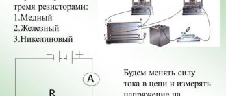
Data for most conductors can be found in reference tables. Specific resistance of metals and alloys, Ohm*mm2/m
(at T = 200C)
| Silver | 0,016 | Bronze (alloy) | 0,1 |
| Copper | 0,017 | Tin | 0,12 |
| Gold | 0,024 | Steel (alloy) | 0,12 |
| Aluminum | 0,028 | Lead | 0,21 |
| Iridium | 0,047 | Nickelin (alloy) | 0,42 |
| Molybdenum | 0,054 | Manganin (alloy) | 0,45 |
| Tungsten | 0,055 | Constantan (alloy) | 0,48 |
| Zinc | 0,06 | Titanium | 0,58 |
| Brass (alloy) | 0,071 | Mercury | 0,958 |
| Nickel | 0,087 | Nichrome (alloy) | 1,1 |
| Platinum | 0,1 | Bismuth | 1,2 |
Most often, the values of ρ are given at normal, that is, room temperature of 200C. But it turned out that with increasing temperature, the resistivity increases linearly in accordance with the formula:
$ ρ(T) = ρ0 * (1 + α*T)$ (6),
where: ρ0 is the resistivity of the conductor at a temperature of 00C, α is the temperature coefficient of resistivity, which also has its own individual meaning for each substance. From formula (6) it follows that the coefficient α has dimension or .
Rice. 2. Temperature dependence of conductor resistivity
In accordance with the Joule-Lenz law, when an electric current flows, heat is released, which means the temperature of the conductor increases. In addition, depending on the area of application, electrical devices can operate at both low (minus) and high temperatures. For accurate calculations of electrical circuits, it is necessary to take into account the dependence ρ(T). The value of α for a specific material can be found in reference literature.
Rice. 3. Reference values of the temperature coefficient of resistivity of conductors
Application
The property of conductors to change resistance at a certain temperature is used to create various elements of electrical circuits and measuring instruments. They will be discussed later in this article.
Resistor
The resistance of older type devices was highly dependent on their heating. When heated, the conductivity of the resistor changed proportionally downward. Electrical circuits require an ideal resistor that has the highest conductivity. To reduce heating in the production of these devices, a material is now used that has a low dependence of resistance on heating temperature. This made it possible to use low-resistance resistors for high-voltage circuits.
Thermistor
There is a separate group of resistors that are used to measure temperature. A feature of such a device is that it can reduce its conductivity when heated. At the same time, it turns off the circuit when a certain threshold value is reached.
Resistance thermometer
This device was designed to measure the temperature of the environment. It consists of a thin platinum wire, a protective cover and a housing. The device has a stable response to temperature changes. The measured value in this device is the resistance of this platinum wire. The higher the temperature, the greater the resistance will be. A decrease in resistance is also recorded, since at this moment the conductivity and resistance change. To measure temperature with a resistance thermometer, wire indicators made of various metals are currently used. Depending on the properties of the metal used, the device error can be no more than 0.1%. This results in very high temperature measurement accuracy.
Gas
The most familiar gas conductor to us is the fluorescent lamp. The gas is heated by increasing the voltage between the anode and cathode of the lamp.
A well-known liquid conductor is the alkaline battery. As the temperature decreases, the structure of the liquid is disrupted and its resistance changes.
Heating causes the movement of atoms and electrons, increasing the resistance and charging current of the device.
Terms
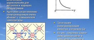
- A semiconductor is a substance with electrical properties that characterize it as a good conductor or insulator.
- The temperature coefficient of resistivity is an empirical quantity (α) that describes the change in resistance or resistivity with temperature.
- Resistivity is the degree to which a material resists electrical flow.
The resistance of materials is based on temperature, so it is possible to trace the dependence of resistivity on temperature. Some are capable of becoming superconductors (zero resistance) at very low temperatures, while others are capable of becoming superconductors at high temperatures. The rate of vibration of atoms increases over long distances, so electrons moving through the metal collide more often and increase resistance. Resistivity changes with temperature ΔT:
The resistance of a particular mercury sample reaches zero at an extremely low temperature (4.2 K). If the indicator is above this mark, then there is a sudden jump in resistance, and then an almost linear increase with temperature
p = p (1 + αΔT), where ρ is the initial resistivity, and α is the temperature coefficient of resistivity. With serious changes in temperature, α can change, and finding p may require a nonlinear equation. That is why sometimes they leave a suffix of the temperature at which the substance changed (for example, α15).
It is worth noting that α is positive for metals, and resistivity increases with temperature. Typically the temperature coefficient is +3 × 10⁻³ K-1 to +6 × 10⁻³ K-1 for metals at approximately room temperature. There are alloys that are specially developed to reduce temperature dependence. For example, manganin has α close to zero.
Do not forget also that α is negative for semiconductors, that is, their resistivity decreases with increasing temperature. They are excellent conductors at high temperatures because increased temperature mixing increases the amount of free charge available to carry current.
An object's resistance is also based on temperature, since R is in direct proportion to p. We know that for a cylinder R = ρL/A. If L and A do not change much with temperature, then R has the same temperature dependence as ρ. It turns out:
Features of conductor resistance
R = R (1 + αΔT), where R is the initial resistance, and R is the resistance after changing the temperature T.
Let's look at the resistance of the temperature sensor. Many thermometers operate according to this scheme. The most common example is the thermistor. This is a semiconductor crystal with a strong temperature dependence. The device is small, so it quickly comes into thermal balance with the human part it touches.
Thermometers are based on automatic measurement of the temperature resistance of the thermistor
Review
Electrical Current Battery Current and Voltage Measurements in Circuits Microscopic View: Drift Speed
Resistance and resistors Ohm's Law Temperature and superconductivity Resistance and resistivity Dependence of resistance on temperature
Electrical energy and energy
Alternating currents Phasors Root mean square value Household precautions
Active and inductive resistance of cables
Electricity in the world People and electrical hazards Nerve conduction and electrocardiograms Electrical activity in the heart
How to increase the strength of electric current. Conductor resistance. Resistivity
Ohm's law is the most important in electrical engineering. That is why electricians say: “Whoever does not know Ohm’s Law should sit at home.” According to this law, current is directly proportional to voltage and inversely proportional to resistance (I = U / R), where R is a coefficient that relates voltage and current.
The unit of measurement for voltage is Volt, resistance is Ohm, and current is Ampere.
To show how Ohm's Law works, let's look at a simple electrical circuit. The circuit is a resistor, which is also a load. A voltmeter is used to record the voltage across it. For load current - ammeter. When the switch is closed, current flows through the load. Let's see how well Ohm's Law is observed. The current in the circuit is equal to: circuit voltage 2 Volts and circuit resistance 2 Ohms (I = 2 V / 2 Ohms = 1 A). The ammeter shows this much. The resistor is a load with a resistance of 2 ohms. When we close switch S1, current flows through the load. Using an ammeter we measure the current in the circuit. Using a voltmeter, measure the voltage at the load terminals. The current in the circuit is equal to: 2 Volts / 2 Ohms = 1 A. As you can see, this is observed.
Now let's figure out what needs to be done to increase the current in the circuit. First, increase the voltage. Let's make the battery not 2 V, but 12 V. The voltmeter will show 12 V. What will the ammeter show? 12 V/ 2 Ohm = 6 A. That is, by increasing the voltage across the load by 6 times, we obtained an increase in current strength by 6 times.
Let's consider another way to increase the current in a circuit. You can reduce the resistance - instead of a 2 Ohm load, take 1 Ohm. What we get: 2 Volts / 1 Ohm = 2 A. That is, by reducing the load resistance by 2 times, we increased the current by 2 times. In order to easily remember the formula of Ohm's Law, they came up with the Ohm triangle: How can you determine the current from this triangle? I = U / R. Everything looks quite clear. Using a triangle, you can also write formulas derived from Ohm’s Law: R = U / I; U = I * R. The main thing to remember is that the voltage is at the vertex of the triangle.
In the 18th century, when the law was discovered, atomic physics was in its infancy. Therefore, Georg Ohm believed that the conductor is something similar to a pipe in which liquid flows. Only liquid in the form of electric current. At the same time, he discovered a pattern that the resistance of a conductor becomes greater as its length increases and less as its diameter increases.
Based on this, Georg Ohm derived the formula: R = p *l / S ,
where p is a certain coefficient multiplied by the length of the conductor and divided by the cross-sectional area. This coefficient was called resistivity, which characterizes the ability to create an obstacle to the flow of electric current, and depends on what material the conductor is made of. Moreover, the greater the resistivity, the greater the resistance of the conductor. To increase the resistance, it is necessary to increase the length of the conductor, or reduce its diameter, or select a material with a higher value of this parameter. Specifically, for copper the resistivity is 0.017 (Ohm*mm2/m).
Dependence of the resistance of platinum thermal resistance on temperature
For industrial platinum resistance thermometers, the Callendar-Van Dusen equation (en) is used, with known coefficients that are established experimentally and standardized in the DIN EN 60751-2009 standard (GOST 6651-2009):
RT=R1+AT+BT2+CT3(T−100)(−200∘C RT=R1+AT+BT2(∘C≤T<850∘C),{\displaystyle R_{T}=R_{0}\ left\;(0\;{}^{\circ }\mathrm {C} \leq T<850\;{}^{\circ }\mathrm {C} ),} here RT{\displaystyle R_{T} } - resistance at temperature T{\displaystyle T} °C, R{\displaystyle R_{0}} resistance at 0 °C, A,B,C{\displaystyle A,B,C} - coefficients - constants normalized by the standard : A=3.9083×10⁻³∘C−1{\displaystyle A=3.9083\times 10^{-3}\;{}^{\circ }\mathrm {C} ^{-1}} B=−5.775 ×10⁻⁷∘C−2{\displaystyle B=-5.775\times 10^{-7}\;{}^{\circ }\mathrm {C} ^{-2}} C=−4.183×10− 12∘C−4.{\displaystyle C=-4.183\times 10^{-12}\;{}^{\circ }\mathrm {C} ^{-4}.}
Since the coefficients B{\displaystyle B} and C{\displaystyle C} are relatively small, the resistance increases almost linearly with increasing temperature.
For platinum thermometers of increased accuracy and reference thermometers, individual calibration is performed at a number of temperature reference points and individual coefficients of the above dependence are determined.
Factors affecting the resistance of semiconductors
It has been experimentally established that as the temperature increases, the electrical resistance in semiconductor crystals decreases. This is due to the fact that when the crystal is heated, the number of free electrons increases, and their concentration increases accordingly. The changing resistance of semiconductors under the influence of temperature is used to create special devices called thermistors.
In order to make a thermistor, semiconductors are used, which are oxides of individual metals in a mixed state. The finished substance is placed in a protective metal case with insulated terminals. With their help, the device is connected to the electrical circuit.
Thermistors are used to measure temperature or to maintain it in a given mode in any devices. The main principle of their operation is changing resistance with temperature changes. The same principle is used in photoresistors. Here the resistance value changes depending on the lighting level.
Semiconductors
How does resistance depend on heating in semiconductors? First, let's talk about thermistors. These are devices that change their electrical resistance under the influence of heat. This semiconductor has a temperature coefficient of resistance (TCR) that is an order of magnitude higher than that of metals. Both positive and negative conductors have certain characteristics.
Where: 1 is TCS less than zero; 2 – TCS is greater than zero.
In order for conductors such as thermistors to start working, any point on the current-voltage characteristic is taken as a basis:
- if the temperature of the element is less than zero, then such conductors are used as relays;
- to control the changing current, as well as what temperature and voltage, use a linear section.
Thermistors are used when checking and measuring electromagnetic radiation, which is carried out at ultra-high frequencies. Due to this, these conductors are used in systems such as fire alarms, heat testing and control of the consumption of bulk media and liquids. Those thermistors with TCR less than zero are used in cooling systems.
Now about thermoelements. How does the Seebeck phenomenon affect thermoelements? The dependence lies in the fact that such conductors function on the basis of this phenomenon. When the temperature of the junction increases with heating, an emf appears at the junction of the closed circuit. Thus, their dependence is manifested and thermal energy is converted into electricity. To fully understand the process, I recommend studying our instructions on how to.
This device is called a thermocouple. Thermoelements are used as low-power current sources, as well as for measuring the temperatures of a digital computing device, whose dimensions must be small and the readings must be accurate.
More details about semiconductors and the effect of heating on their resistance are described in the video:
Well, the last thing I would like to talk about is refrigerators and semiconductor heaters. Semiconductor junctions provide a temperature difference of up to sixty degrees in the design. Thanks to this, the refrigerator was designed. The cooling temperature in such a chamber reaches – 16 degrees. The operation of the elements is based on the use of thermoelements through which electric current passes.
In his practical activities, every electrician encounters different conditions for the passage of charge carriers in metals, semiconductors, gases and liquids. The magnitude of the current is affected by electrical resistance, which changes in various ways under the influence of the environment.
One of these factors is temperature exposure. Since it significantly changes the conditions for the flow of current, it is taken into account by designers in the production of electrical equipment. Electrical personnel involved in the maintenance and operation of electrical installations are required to competently use these features in practical work.
The influence of temperature on the electrical resistance of metals
In a school physics course, it is proposed to carry out the following experiment: take an ammeter, a battery, a piece of wire, connecting wires and a burner. Instead of an ammeter with a battery, you can connect an ohmmeter or use its mode in a multimeter.
Now let's bring the burner flame to the wire and begin to heat it. If you look at the ammeter, you will see that the arrow will move to the left and reach the position marked in red.
The result of the experiment demonstrates that when metals are heated, their conductivity decreases and their resistance increases.
The mathematical justification for this phenomenon is given by the formulas directly in the picture. In the lower expression it is clearly seen that the electrical resistance “R” of a metal conductor is directly proportional to its temperature “T” and depends on several other parameters.
How heating metals limits electric current in practice
Incandescent lamps
Every day, when we turn on the lighting, we encounter the manifestation of this property in incandescent lamps. Let's carry out simple measurements on a light bulb with a power of 60 watts.
Using the simplest ohmmeter, powered by a low-voltage 4.5 V battery, we measure the resistance between the contacts of the base and see the value of 59 Ohms. The filament has this value when it is cold.
Screw the light bulb into the socket and connect the 220 volt home network voltage to it through an ammeter. The ammeter needle will show 0.273 ampere. Let us determine the resistance of the thread in a heated state. It will be 896 Ohms and will exceed the previous ohmmeter reading by 15.2 times.
This excess protects the metal of the filament body from burnout and destruction, ensuring its long-term performance under voltage.
Power-on transients
When the filament operates, a thermal balance is created between the heating from the passing electric current and the removal of part of the heat to the environment. But, at the initial stage of switching on, when voltage is applied, transient processes occur that create an inrush current, which can lead to burnout of the filament.
Transient processes occur in a short time and are caused by the fact that the rate of increase in electrical resistance from heating the metal does not keep pace with the increase in current. After their completion, the operating mode is established.
During prolonged luminescence of the lamp, the thickness of its filament gradually reaches a critical state, which leads to burnout. Most often, this moment occurs during the next new switch on.
To extend the life of the lamp, this inrush current is reduced in various ways, using:
1. devices that provide smooth supply and release of tension;
2. circuits for connecting resistors, semiconductors or thermistors (thermistors) in series to the filament.
An example of one way to limit the inrush current for automotive lamps is shown in the picture below.
Here, the current to the light bulb is supplied after turning on the toggle switch SA through the fuse FU and is limited by a resistor R, the value of which is selected so that the current surge during transient processes does not exceed the rated value.
When the filament heats up, its resistance increases, which leads to an increase in the potential difference across its contacts and the parallel-connected relay winding KL1. When the voltage reaches the relay setting value, the normally open contact KL1 will close and shunt the resistor. The operating current of the already established mode will begin to flow through the light bulb.
The effect of metal temperature on its electrical resistance is used in the operation of measuring instruments. They are called .
Their sensitive element is made of a thin metal wire, the resistance of which is carefully measured at certain temperatures. This thread is mounted in a housing with stable thermal properties and covered with a protective cover. The created structure is placed in an environment whose temperature must be constantly monitored.
Wires of the electrical circuit are mounted on the terminals of the sensitive element, which connect the resistance measuring circuit. Its value is converted into temperature values based on the previously performed calibration of the device.
Baretter - current stabilizer
This is the name of a device consisting of a sealed glass cylinder with hydrogen gas and a metal wire spiral made of iron, tungsten or platinum. This design resembles an incandescent light bulb in appearance, but it has a specific current-voltage nonlinear characteristic.
On the current-voltage characteristic, in a certain range, a working zone is formed, which does not depend on fluctuations of the voltage applied to the body. In this section, the barter compensates well for power ripples and works as a current stabilizer on a load connected in series to it.
The operation of the baretter is based on the property of thermal inertia of the filament body, which is ensured by the small cross-section of the filament and the high thermal conductivity of the hydrogen surrounding it. Due to this, when the voltage on the device decreases, heat removal from its filament accelerates.
This is the main difference between the baretter and incandescent lighting lamps, in which, to maintain the brightness of the glow, they strive to reduce convective heat loss from the filament.
Superconductivity
Under normal environmental conditions, when a metal conductor is cooled, its electrical resistance decreases.
When a critical temperature is reached, close to zero degrees according to the Kelvin measurement system, there is a sharp drop in resistance to zero. The right picture shows such a relationship for mercury.
This phenomenon, called superconductivity, is considered a promising area for research with the goal of creating materials that can significantly reduce the loss of electricity when transmitting it over vast distances.
However, ongoing studies of superconductivity have revealed a number of patterns when the electrical resistance of a metal located in the critical temperature region is influenced by other factors. In particular, when alternating current passes with an increase in the frequency of its oscillations, resistance arises, the value of which reaches the range of usual values for harmonics with a period of light waves.
Effect of temperature on electrical resistance/conductivity of gases
Gases and ordinary air are dielectrics and do not conduct electricity. For its formation, charge carriers are needed, which are ions formed as a result of exposure to external factors.
Heating can cause ionization and movement of ions from one pole of the medium to the other. You can verify this using a simple experiment. Let's take the same equipment that we used to determine the effect of heating on the resistance of a metal conductor, but instead of wire, we will connect two metal plates separated by air space to the wires.
An ammeter connected to the circuit will indicate the absence of current. If a burner flame is placed between the plates, the needle of the device will deviate from the zero value and show the amount of current passing through the gaseous medium.
Thus, it was established that ionization occurs in gases when heated, leading to the movement of electrically charged particles and a decrease in the resistance of the medium.
The current value is affected by the power of the external applied voltage source and the potential difference between its contacts. It is capable of breaking through the insulating layer of gases at high values. A typical manifestation of such a case in nature is a natural lightning discharge during a thunderstorm.
An approximate view of the current-voltage characteristic of the flow of current in gases is shown in the graph.
At the initial stage, under the influence of temperature and potential difference, an increase in ionization and the passage of current is observed approximately according to a linear law. Then the curve becomes horizontal when an increase in voltage does not cause an increase in current.
The third stage of breakdown occurs when the high energy of the applied field accelerates the ions so much that they begin to collide with neutral molecules, massively forming new charge carriers from them. As a result, the current increases sharply, forming a breakdown of the dielectric layer.
Practical use of gas conductivity
The phenomenon of current flowing through gases is used in electronic tubes and fluorescent lamps.
To do this, two electrodes are placed inside a sealed glass cylinder with an inert gas:
1. anode;
2. cathode.
In a fluorescent lamp, they are made in the form of filaments, which heat up when turned on to create thermionic emission. The inner surface of the flask is covered with a layer of phosphor. It emits the visible spectrum of light produced by infrared radiation emanating from mercury vapor bombarded by a stream of electrons.
The gas discharge current occurs when a voltage of a certain magnitude is applied between the electrodes located at different ends of the flask.
When one of the filaments burns out, the electron emission at this electrode will be disrupted and the lamp will not light. However, if you increase the potential difference between the cathode and anode, a gas discharge will again occur inside the bulb and the glow of the phosphor will resume.
This allows you to use LED bulbs with damaged filaments and extend their service life. Just keep in mind that in this case the voltage on it must be increased several times, and this significantly increases the power consumption and the risks of safe use.
The influence of temperature on the electrical resistance of liquids
The passage of current in liquids is created mainly due to the movement of cations and anions under the influence of an externally applied electric field. Only a small part of the conductivity is provided by electrons.
The effect of temperature on the electrical resistance of a liquid electrolyte is described by the formula shown in the picture. Since in it the value of the temperature coefficient α is always negative, then with increasing heating the conductivity increases and the resistance drops as shown in the graph.
This phenomenon must be taken into account when charging liquid automotive (and other) batteries.
The influence of temperature on the electrical resistance of semiconductors
Changes in the properties of semiconductor materials under the influence of temperature have made it possible to use them as:
- thermal resistances;
thermoelements;
refrigerators;
heaters.
Thermistors
This name refers to semiconductor devices that change their electrical resistance under the influence of heat. They are significantly higher than those of metals.
The TCR value for semiconductors can have a positive or negative value. According to this parameter, they are divided into positive “RTS” and negative “NTC” thermistors. They have different characteristics.
To operate the thermistor, select one of the points on its current-voltage characteristic:
- the linear section is used to control temperature or compensate for changing currents or voltages;
descending branch of the current-voltage characteristic for elements with TCS
The use of a relay thermistor is convenient when monitoring or measuring electromagnetic radiation processes occurring at ultrahigh frequencies. This ensured their use in systems:
1. heat control;
2. fire alarm;
3. regulation of the flow of bulk media and liquids.
Silicon thermistors with a small TCR>0 are used in cooling systems and temperature stabilization of transistors.
Thermoelements
These semiconductors operate on the basis of the Seebeck phenomenon: when the soldered area of two disparate metals is heated, an emf is generated at the junction of a closed circuit. In this way they convert thermal energy into electricity.
A structure of two such elements is called a thermocouple. Its efficiency lies within 7÷10%.
Thermoelements are used in temperature meters of digital computing devices that require miniature dimensions and high accuracy of readings, and also as low-power current sources.
Semiconductor heaters and refrigerators
They work by reversing the use of thermocouples through which an electric current is passed. In this case, at one place of the junction it is heated, and at the opposite place it is cooled.
Semiconductor junctions based on selenium, bismuth, antimony, and tellurium make it possible to ensure a temperature difference in the thermoelement of up to 60 degrees. This made it possible to create a refrigerated cabinet design made from semiconductors with temperatures in the cooling chamber down to -16 degrees.
The resistance of metals is due to the fact that electrons moving in a conductor interact with ions of the crystal lattice and thereby lose part of the energy that they acquire in the electric field.
Experience shows that the resistance of metals depends on temperature. Each substance can be characterized by a constant value for it, called the temperature coefficient of resistance α
.
This coefficient is equal to the relative change in the resistivity of the conductor when it is heated by 1 K: α =
where ρ 0 is the resistivity at a temperature T 0 = 273 K (0°C), ρ is the resistivity at a given temperature T. Hence the dependence of the resistivity of the metal conductor temperature is expressed by a linear function: ρ = ρ 0 (1+ αT).
The dependence of resistance on temperature is expressed by the same function:
R = R 0 (1+ αT).
The temperature coefficients of resistance of pure metals differ relatively little from each other and are approximately equal to 0.004 K -1. A change in the resistance of conductors with a change in temperature leads to the fact that their current-voltage characteristic is not linear. This is especially noticeable in cases where the temperature of the conductors changes significantly, for example when operating an incandescent lamp. The figure shows its volt-ampere characteristic. As can be seen from the figure, the current strength in this case is not directly proportional to the voltage. However, one should not think that this conclusion contradicts Ohm's law. The dependence formulated in Ohm's law is valid only with constant resistance.
The dependence of the resistance of metal conductors on temperature is used in various measuring and automatic devices.
The most important of these is the resistance thermometer
.
The main part of the resistance thermometer is a platinum wire wound on a ceramic frame. The wire is placed in a medium whose temperature needs to be determined. By measuring the resistance of this wire and knowing its resistance at t 0 = 0 °C (i.e. R 0),
the temperature of the medium is calculated using the last formula.
Superconductivity.
However, until the end of the 19th century. it was impossible to check how the resistance of conductors depends on temperature in the region of very low temperatures. Only at the beginning of the 20th century. The Dutch scientist G. Kamerlingh Onnes managed to transform the most difficult to condense gas, helium, into a liquid state. The boiling point of liquid helium is 4.2 K. This made it possible to measure the resistance of some pure metals when they are cooled to a very low temperature.
In 1911, the work of Kamerlingh Onnes culminated in a major discovery. Studying the resistance of mercury as it was constantly cooled, he discovered that at a temperature of 4.12 K the resistance of mercury dropped abruptly to zero. Subsequently, he was able to observe the same phenomenon in a number of other metals when they were cooled to temperatures close to absolute zero. The phenomenon of complete loss of electrical resistance by a metal at a certain temperature is called superconductivity.
Not all materials can become superconductors, but their number is quite large. However, many of them were found to have a property that significantly hampered their use. It turned out that for most pure metals, superconductivity disappears when they are in a strong magnetic field. Therefore, when a significant current flows through a superconductor, it creates a magnetic field around itself and superconductivity disappears in it. Nevertheless, this obstacle turned out to be surmountable: it was found that some alloys, for example, niobium and zirconium, niobium and titanium, etc., have the property of maintaining their superconductivity at high current values. This allowed for more widespread use of superconductivity.
The resistance of conductors depends on the substance from which they are made and their geometric dimensions
R =
ρ. l/ S,
where ρ
- specific resistance of the substance from which the conductor is made;
l
is the length of the conductor;
S is
the cross-sectional area of the conductor.
The resistance of conductors is included in Ohm's law for a homogeneous section of the circuit I =
U / R
R = U / I
can be determined .
From the last formula it turns out that the resistance of the conductor is constant, since, in accordance with Ohm’s law, by how many times we increase the voltage at the ends of the conductor, the current strength in it increases by the same amount.
But in practice, other phenomena can be observed. Let's make an electrical circuit, the diagram of which is shown in Fig. 7.2. In this circuit there is a current source with a regulated voltage, an electric lamp, for example, a car lamp, a voltmeter and an ammeter that show the voltage on the lamp and the current in it. Set the lamp voltage U 1
and note the current strength
I 1.
If you now increase the voltage, for example, by 2 times
( U 2 =
2
U 1),
then according to Ohm’s law the current strength should increase by 2 times (
I 2
= 2
I 1).
However, the ammeter shows a current strength significantly less than 2
I 1
.
Consequently, in this case Ohm's law is not satisfied.
There is a discrepancy between your previous knowledge and a new fact for you - Ohm’s law is not always fair. Such a discrepancy in science is called a problem.
A problem
(gr. - task, difficulty) is a complex theoretical or practical issue that requires a solution.
Various assumptions can be made that are an attempt to explain the observed phenomenon. However, during the experiment it is striking that with increased voltage the lamp glows brighter than in the first case. This is evidence that the temperature of the lamp coil in the second case is higher than in the first. Perhaps it is the change in temperature that causes the change in the resistance of the metal coil of the lamp.
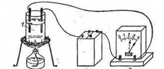
How can one check such an assumption (hypothesis)? We make an electrical circuit (Fig. 7.3), in which there is a metal conductor in the form of a spiral, for example, a spring from a ballpoint pen, and set a current of a certain strength in the circuit. When heating the spiral in the flame of a candle or match, we note:
When the spiral is heated and at a constant voltage, the current strength in the circuit decreases, which indicates an increase in the resistance of the spiral as its temperature increases.
Careful studies show that the resistance of metal conductors depends almost linearly on their temperature
R =
R 0 (
1
+ α t°),
where R 0
— conductor resistance at 0 °C or +20 °C (this is more convenient for technology). A graph of such a dependence is presented in Fig. 7.4.
If we keep in mind that the dimensions of metals change little when heated, then the corresponding formula can be written for the resistivity of metal conductors
ρ =
ρ 0 (
1
+ α t°).
Let's consider what the coefficient means in the resulting formulas. If at 0°C the conductor resistance is R 0,
and at
t°
C its resistance
is R,
then the relative change in resistance, as experiment shows,
( R - R 0) / R 0 = α t °
C. Material from the site
The proportionality coefficient is called the temperature coefficient of resistance
, which characterizes the dependence of the resistance of a substance on its temperature.
The temperature coefficient of resistance
is equal to the relative change in the resistance of the conductor when its temperature changes by 1 K.
For all metal conductors α
> 0 and depends little on temperature.
Why does the resistance of metal conductors increase with increasing temperature? The fact is that when the metal is heated, the intensity of vibrations of the ions of the crystal lattice and the speed of the chaotic movement of electrons increases.
Electrons collide with ions more often, which reduces the speed of their directional movement, which is an electric current.
In technology, the dependence of the resistance of metal conductors on temperature is used in resistance thermometers.
A temperature sensor (for example, a platinum wire) is installed at those points where it is necessary to measure temperature, and its resistance is measured with an ohmmeter, the scale of which is graduated in temperature units. If necessary, there can be any number of such sensors, but there can be only one measuring device.
On this page there is material on the following topics:
Graph of resistance versus temperature in vacuum
Dependence of resistance on temperature for vacuum
Dependence of resistance in vacuum on temperature
Dependence of resistance of metal conductors on temperature
Liquids
Current conductors in a liquid are anions and cations that move due to an external electric field. Electrons provide little conductivity. Let's consider the dependence of resistance on temperature in liquids.
Where:
- Electrolyte
- Battery
- Ammeter
The dependence of the effect of electrolytes on heating is prescribed by the formula:
Where a is the negative temperature coefficient.
How R depends on heating (t) is shown in the graph below:
This dependence must be taken into account when charging batteries and batteries.
Metals
How does temperature affect metals? To find out this relationship, the following experiment was carried out: a battery, an ammeter, a wire and a burner are connected to each other using wires. Then you need to measure the current in the circuit. After the readings have been taken, you need to bring the burner to the wire and heat it. When the wire is heated, it can be seen that the resistance increases and the conductivity of the metal decreases.
Where:
- Metal wire
- Battery
- Ammeter
The dependence is indicated and justified by the formulas:
From these formulas it follows that R of the conductor is determined by the formula:
An example of the dependence of metal resistance on temperature is provided in the video:
You also need to pay attention to such a property as superconductivity. If the environmental conditions are normal, then as the conductors cool, they reduce their resistance
The graph below shows how temperature and resistivity vary in mercury.
Superconductivity is a phenomenon that occurs when a material reaches a critical temperature (closer to zero Kelvin) at which the resistance suddenly decreases to zero.
How to find out the resistance of 1 meter of copper wire
After finding out all the factors that influence the resistance of a copper wire, you can combine them in the formula for the dependence of resistance on the cross-section of the conductor and find out how to calculate this parameter. The mathematical expression is as follows: R= pl/s, where:
- ρ—resistivity;
- l is the length of the conductor, when finding the resistance of a copper conductor 1 m long, l = 1;
- S—cross-sectional area.
To calculate S, in the case of a cylindrical wire, the formula is used: S = π ∙ r2 = π d2/4 ≈ 0.785 ∙ d2, here:
- r is the radius of the wire section;
- d is its diameter.
If the wire consists of several cores, then the total area will be equal to: S = n d2/1.27, where n is the number of cores.
If the conductor has a rectangular shape, then S = a ∙ b, where a is the width of the rectangle, b is the length.
Important! You can find out the diameter of the section using a caliper. If it is not at hand, then wind the measured wire around any rod, count the number of turns, preferably there should be at least 10 for greater accuracy
After this, measure the wound part of the conductor and divide the value by the number of turns.
Calculation of cross-sectional area