Differential current protection is one of the types of relay protection, which is characterized by high efficiency and also has relatively good response speed. It is used both for power equipment (motors, transformers, generators and bus sections), and recently it has become widely used to protect household objects from phase faults. This became possible due to special compact devices similar in design to a regular circuit breaker.
However, some power equipment is simply required, according to power supply regulations, to be equipped with high-speed differential relay protection. Among the varieties of DFZ, there are two main types:
- longitudinal;
- transverse
In order to understand whether differential phase protection is needed for a particular electrical equipment and how to implement it, you need to understand the principle of its operation, as well as understand the installation nuances.
Operating principle of differential protection
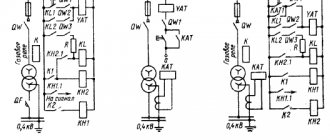
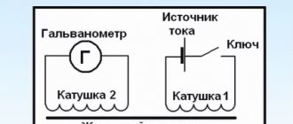
The action of this protection is based on comparing the currents that enter and exit the area in need of protection. For such a comparison of current values, current transformers are used, since only through them is it possible to measure large current values. This is best seen in the simplest diagram below.
In the diagram, the current transformers are designated TA1 and TA2. Their secondary circuits are connected to the KA current relay. Thus, it turns out that the winding of the main protection relay receives the difference in current values from the two transformers, and during normal operating processes it will be equal to zero, which means the KA relay will remain unplugged. However, if an interphase short circuit (short circuit) occurs in the circuit that is being protected, then the relay winding will receive a value equal to the sum of several currents, this will set in motion the moving part of the electromechanical relay, which, in turn, will close the contacts and will give a signal to disconnect the equipment from the source of electrical energy. However, this is all in theory, but in practice a certain small unbalance current will always flow through the relay coil, which must be taken into account when calculating the coil.
Here are several reasons for this negative phenomenon:
- CTs (current transformers) can have characteristics that differ significantly from each other. To reduce these indicators, more precise transformers are used, manufactured in pairs specifically for this type of protection;
- Due to the magnetizing current arising in the winding of the protected transformer at the moment it is turned on from the idle mode to the operating mode with a load present. In order to avoid false operation of the KA relay, it is necessary to select a relay operation current greater than the highest value of the magnetizing current that the protected object, in this case a transformer, can produce;
- Due to different connections of windings (star-delta and vice versa). To do this, you need to select the number of turns of current transformers involved in differential protection in such a way that they compensate for these unfavorable values.
The unbalance current in differential protection that occurs during operation is a negative phenomenon that must be combated and which must be taken into account when calculating this protective electrical equipment.
Longitudinal differential protection
Advantages:
- absolute selectivity;
- can be used without restrictions with other types;
- fail-safe for short-length power lines;
- without a time delay, disconnects the emergency section of the network.
Flaws:
- When designing differential protection for long power lines, its effectiveness is significantly reduced. To correct the operation, devices for monitoring the failure of auxiliary wires are required;
- unbalance current occurs;
- high cost when using relays with braking;
- complexity of implementation - it is necessary to construct a communication line between the sections of conductors to which the current transformer is connected.
Scope:
- autotransformer and transformer protection;
- protection at the substation of a single transformer or autotransformer with an installed capacity of more than 6300 kVA;
- differential protection of parallel operating transformers with a power of more than 1000 kVA, if the current cutoff performs its function correctly.
Transformer differential protection
Operating principle
The operating principle of differential protection devices is based on comparing the value of current loads flowing through protective devices in sections of the line. To measure current strength, it is advisable to use a transformer. The circuits of two CTs are connected to the relay so that it is not affected by the difference in current values between the windings of the transformers. Under real operating conditions, an unbalance current is always present.
The occurrence of unbalance current
- The occurrence of magnetizing currents in the windings of a transformer. In some cases, for example, from the action of switching from idle mode to full load, its value may exceed the nominal value. In this regard, the relay setting current is selected greater than the maximum value of the magnetizing current.
- CTs do not always exactly match each other in terms of technical characteristics. To avoid negative consequences, the principle of testing transformers in production is to select suitable pairs, which are supplied in kits.
- Winding connection. With different connections (star-delta, for example), unbalance currents also arise. The equalization of electric current values cannot be solved by selecting the turns of the current transformer. The angle shift is compensated by connecting the windings: a triangle for a star and vice versa.
Modern microprocessor-based longitudinal differential protection is equipped with an unbalance current compensation device.
Tire differential protection (TIP)
Features of the application and operation of various transformer protections
Busbars and busbar assemblies are a key reliable current-carrying element of an electrical installation, connecting the voltage source to the switchgear or the operating unit itself. It is characterized by high load capacity and the ability to visually monitor the condition of insulators. At the same time, many people know that it is necessary to implement circuits that protect electrical equipment, but the busbars very often remain unprotected.
Main types of tire damage:
- Incorrect or erroneous manipulations by maintenance personnel with switching of bus disconnectors;
- Phase overlap or short circuit to ground due to deterioration of insulation through contamination of insulators;
- Breakdown during aggressive atmospheric phenomena (thunderstorm, lightning);
- Malfunctions of the disconnector insulators on both sides.
To protect busbars, differential current protection is mainly used. The principle of its operation is similar, and is based on comparing the currents in the connections of the protected buses. When the busbars are in normal operating condition, only unbalance current flows in the differential protection relay coil, which does not operate the relay moving mechanism. During a phase fault, the protection relay will receive a current whose value will be equal to the sum of all currents supplying the connection where the breakdown occurred.
The main advantages of such protection are:
- High response speed;
- Excellent selectivity;
- Relatively simple implementation.
There is only one drawback here - it is a false alarm, which is most often possible when the installation (connecting) wires break, which can occur due to various reasons, both electrical and mechanical. In order to minimize the probability of false triggering, it is necessary to select the operating current of the DPS a little more than the operating current of the most powerful connection. The coverage area of this protection is limited directly to the gap where the CTs are installed; its operation is aimed at disconnecting all supply connections from voltage. To manually monitor the unbalance current, a milliammeter is installed on the control panel and maintenance personnel are required to check it by pressing the corresponding button. Personnel are required to perform this action once per shift, recording it in the operational log.
The differential protection of the busbar is disabled in the following cases:
- The appearance of a sound or light signal about a malfunction of current circuits or an increase in unbalance current;
- If a new connection has occurred, the current circuits of which are not connected to the protection system, and were not correctly phased;
- During a routine check of this protection.
Protection of household networks (RCD)
The operation of devices with differential protection installed at inputs to administrative and residential buildings does not differ significantly from the previously discussed principle of operation for transformers and motors. They also have a sensitive element that responds to an imbalance of incoming and outgoing current and reacts when it occurs by disconnecting the consumer from the supply line.
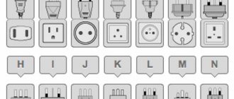
Devices of this class, used for the purposes indicated above, are called RCDs (see figure below).
Line protection with RCD
The cause of current imbalance in domestic conditions may be the following factors:
- Touch of a person or animal to exposed current carriers (wires) or to equipment housing exposed to dangerous potential;
- Destruction of electrical wiring insulation with the risk of short circuit;
- Increased humidity in the room being served (in the bathroom, for example);
- Damage to cables of household electrical appliances resulting in leakage to ground.
Note! In cases where the ouzo system operates without any disturbances in the operation of the consumer (without load from leakage currents), it should be assumed that this device is faulty and must be repaired. A feature of the functioning of RCD systems is their response to microscopic leakage currents (μA), recorded when the slightest “suspicious” passive or capacitive connection to ground appears
Moreover, such a system operates almost instantly, providing one hundred percent protection of a person from electric shock.
A feature of the functioning of RCD systems is their response to microscopic leakage currents (μA), detected when the slightest “suspicious” passive or capacitive connection to the ground appears. Moreover, such a system operates almost instantly, providing one hundred percent protection of a person from electric shock.
In electrical engineering, it is accepted as a rule that it is possible to provide effective differential protection using an RCD only when using a three-level circuit. This means that several devices are connected in series to the protected line, designed for three levels of leakage current values: 100-300, 30 and 10 mA, respectively.
Important! Such current protection, operating on the differential principle, can be effective even at facilities where the wiring does not include a grounding bus. Another feature of this device is the need to periodically (at least once a month) check its performance, for which it has a special button called “Test” or “Check”
In addition to the control button, the testing circuit includes a limiting resistor through which a certain current corresponding to an emergency situation is passed during testing.
Another feature of this device is the need to periodically (at least once a month) check its performance, for which it has a special button called “Test” or “Check”. In addition to the control button, the testing circuit includes a limiting resistor through which a certain current corresponding to an emergency situation is passed during testing.
Longitudinal differential generator protection
Features of installation of electrical equipment
To protect various generators from multiphase short circuits. longitudinal differential protection has received the most widespread use. It is connected in the same way as the previous one to the CT, only they are installed from the zero point of the generator, as well as from the terminals. Its coverage area is:
- windings of an electric machine;
- stator output;
- buses or cables that are laid to the switchgear.
The operation current of such protection is set according to the condition of setting the unbalance current passing through the differential protection relay during external short circuits. A protection circuit for a high-sensitivity generator is presented, using the most reliable RNT relays for this case.
The operation current of such a circuit is set according to two conditions:
- Setting the actual unbalance current;
- Setting the current that will flow when the installation wires break.
Generator transverse differential protection
Features of the application and use of the RCD device
This protection is performed to protect against vik short circuits that can occur directly in the stator winding, and, of course, if there are parallel branches of the stator windings. This is possible by comparing the current values of these branches for each phase. Transverse differential protection is carried out in such a way that for each of the phases it is organized separately, that is, it will respond to interturn short circuits only in one of the phases.
The current at which the transverse differential protection coil is drawn in is adjusted according to the maximum unbalance current that can flow in the relay during various external short circuits, and is taken equal to:
When setting up a differential protection system, it is recommended to make a more accurate calculation of the setting, taking into account absolutely all actual unbalance currents flowing, and not calculated ones. As experience shows during operation, on turbogenerators they are relatively small, and their operating current does not require additional adjustments and adjustments. On hydrogenerators, on the contrary, the magnitudes of these unwanted currents are large, therefore it is necessary to significantly coarse the settings of the relay of this transverse protection, which sometimes reduces its super-efficiency.
As a result, I would like to note that the calculation and configuration of these protections should only be carried out by professionals who have experience in this field, most often these are engineers from electrical design bureaus. Differential phase protection in everyday life is also very effective and even a novice electrician can perform it on the basis of compact devices sold in specialized stores; there should not be any connection difficulties. The main thing is to follow basic electrical safety rules.