Settings
Modern oscilloscopes do not require any setup before use, but nevertheless, most oscilloscopes have a built-in calibration device (Calibrator).
The purpose of this device is to generate a control signal with known and stable parameters. Typically, such a signal has the form of rectangular pulses with an amplitude of 1 Volt, a frequency of 1 kHz and a duty cycle of 50% (the parameters are usually indicated next to the output of the calibrator signal). At any time, the user of an oscilloscope can connect the measuring probe of the device to the output of the calibrator and make sure that a signal with the specified parameters is visible on the oscilloscope screen. If the signal differs from that indicated on the calibrator, which is more typical for analog oscilloscopes, then using a trimming screwdriver the user can adjust the input characteristics of the probe or the oscilloscope amplifiers so that the signal matches the calibrator data
It is worth noting that modern digital oscilloscopes do not have trimming elements due to the use of digital signal processing, but have automatic adjustment using a calibrator, when a special utility is called through the oscilloscope menu, which introduces correction factors into the mathematical block of the oscilloscope and thereby configures the oscilloscope to correctly display signals .
If the signal differs from that indicated on the calibrator, which is more typical for analog oscilloscopes, then using a trimming screwdriver the user can adjust the input characteristics of the probe or the oscilloscope amplifiers so that the signal matches the data of the calibrator. It is worth noting that modern digital oscilloscopes do not have trimming elements due to the use of digital signal processing, but have automatic adjustment using a calibrator, when a special utility is called through the oscilloscope menu, which introduces correction factors into the mathematical block of the oscilloscope and thereby configures the oscilloscope to correctly display signals .
How to use an oscilloscope and why you need it. Part II
This is the second part of an educational program on oscilloscopes, and the first part is here.
This note will be gradually updated with simple but useful techniques for working with an oscilloscope.
Introduction
The main question to answer is: “what can you measure with an oscilloscope?” As you already know, this device is needed to study signals in electrical circuits. Their shapes, amplitudes, frequencies. Based on the data obtained, we can draw conclusions about other parameters of the circuit under study. This means that with the help of an oscilloscope you can basically (I’m not talking about the super functions of super-modern devices):
- Determine Waveform
- Determine the frequency and period of the signal
- Measure signal amplitude
- Not directly, but you can also measure the current (Ohm’s law in your hands)
- Determine the signal phase shift angle
- Compare signals with each other (if the device allows)
- Determine frequency response
- Forgot to mention something? Remind me in the comments!
All further examples should be done with an analog oscilloscope in mind. For digital everything is the same, but it can do more than analog and in certain matters eliminates the need to think where you can simply show a number. A good tool should be like that.
So, before work, you should prepare the device: put it on the table, connect it to the network =) Oh well, I’m just kidding. But if possible, it should be grounded. If there is a built-in calibrator, then according to the instructions for the device you need to calibrate it. (hint: instructions are online).
You will connect your oscilloscope to the circuit under study using a probe. This is a coaxial wire, at one end of which there is a connector for connecting to an oscilloscope, and at the other end there is a probe and ground for connection to the circuit under study. Any random wire cannot be used as a probe. Only special probes. Otherwise, instead of the real picture of things, you will see nonsense.
I will not look at each oscilloscope control in detail. There are a lot of such reviews on the Internet. Let's better learn how to carry out amateur measurements: we will determine the amplitude, frequency and period of the signal, shape, amplifier bandwidth, filter cutoff frequency, power supply ripple level, etc. Other tricks and tricks will come with practice. You will need an oscilloscope and a signal generator.
Types of signals
I will speak without lordly tricks, like a peasant. On the oscilloscope screen you will see either a sinusoidal signal, or a saw, or rectangles, or a triangular signal, or just some nameless graph.
There are countless types of signals. And the signals themselves do not know that they belong to some species. So your task is not to remember the names, but to look at the screen and quickly figure out what you see on it means, what process is going on in the circuit.
Amplitude, frequency, period
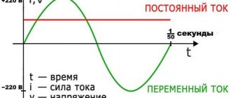
The oscilloscope can measure both DC and AC voltage. All devices have two modes for this: measuring only an alternating signal, measuring a constant and alternating signal simultaneously.
This means that if you choose to measure an alternating signal and connect the probe to a battery, then nothing will change on the device screen. And if you choose the second mode and do the same thing, then the line on the device screen will shift upward by approximately 1.6V (the value of the emf of a finger-type battery). Why is this necessary? To separate the DC and AC components of the signal!
Example. You have decided to measure the ripple in a newly assembled 30V DC voltage source. You connect it to an oscilloscope, and the beam runs far up. In order to conveniently observe the signal, you will have to select the maximum value of V/div per cell. But then you definitely won’t see the pulsations. They are too small. What to do? Switch the input mode to measure alternating voltage and turn the V/Div knob to a much smaller scale. The DC component of the signal will not pass through and only the ripples of the power source will be shown on the screen.
It is easy to determine the amplitude of the alternating voltage by knowing the value of the V/div division and simply count the number of cells along the ordinate axis that this signal occupies from the zero value (average) to the maximum.
If you look at the oscilloscope screen in the picture above and assume that V/div = 1V, then the amplitude of the sine wave will be 1.3V.
And if we assume that Time/div (sweep) is set to 1 millisecond, then the period of this sine wave will occupy 4 cells, and the period T = 4 ms will be read. Easily? Let's now calculate the frequency of this sine wave. Frequency and period are related by the formula: F = 1/T (T in seconds). Therefore F = 1/ (4*10 -3) and equals 250 Hz.
Of course, this is a very rough estimate, which is only suitable for such clean and beautiful signals. And if you submit some kind of musical composition instead of a pure sine wave, then it will contain many different frequencies and you can’t guess by eye. To determine which frequencies are included in this composition, you will need a spectrum analyzer. And this is a different device.
Frequency measurement
As I wrote above, you can also measure frequency using an oscilloscope. You can also not only measure the frequency of a sinusoidal signal, but even compare the frequencies of two signals, for example, using Lissajous figures.
Measuring voltage
To reduce errors, since observation is visual, it is recommended that the graph occupy 80–90% of the monitor. When measuring voltage and frequency (there is a time interval), it is necessary to place the gain and sweep speed controls in the extreme right positions.
Procedure
Voltage is measured by vertical scaling. Algorithm:
- Before starting, connect the probe signal to its own ground wire (needle to “crocodile”) or set the input mode toggle switch to the “ground” position.
- The “pulse of a corpse” will be displayed, if not, then you need to move the offset, stabilization and level - perhaps the image was hidden and did not start.
- We use the selectors to adjust the shift of the strip to zero and use the “up-down” regulator to set the scan to the horizontal grid, so it will be possible to correctly calculate the height of the oscillogram. If the oscilloscope is old or analog, then you need to let it warm up for about 5 minutes.
- We set the voltage measurement limit, it is recommended to take it with a reserve, then you can reduce it.
- A signal is given to the input (or its switch is moved to one of the operating positions). A graph will appear on the monitor.
- Let's illustrate the process: the battery has 1.5 V, if you touch the ground branch of the probe to its minus, and the signal branch to the plus, then a graph jump of 1.5 Volts will appear.
To find the height of the graph, move the oscillogram with the selector so that the mark by which the amplitude is calculated is on the central vertical with fractions. We get the sensitivity of the deviation - 1 v/div, the size of the oscilloscope. - 2.6 div., and hence ampl. = 2.6 V.
Below is an illustration on an analog device: 3.4 div. — max. voltage. The next picture shows vertical scaling. The “smooth” regulator (the part with the green mark) is in the right limit position, the sensitivity toggle switch is 0.5 V/div. Scale multiplier — ×10. Voltage calculation:
Operating principle
The general principle of operation of the device is simple. It registers any change in the voltage of the signal under test and displays it on the display. Since the time of the recorder invented by André Blondal, where an inductive coil controlled the oscillations of a pendulum, the idea has undergone changes. After the invention of the cathode ray tube (CRT), the device became a full-fledged meter. The controls are on the front panel.
DIY oscilloscope
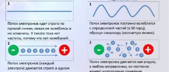
The signal applied to the input can have different amplitudes. The “V/div” knob located on the front panel allows you to stretch or reduce the resulting image along the Y axis. The “duration” knob changes the speed of the beam moving across the display. This is the sweep frequency.
For your information. The beam constantly moves from left to right, its vertical deviation is determined by the impulse arriving at the input. The result is a sine wave or other oscillations on the display.
Using the scan frequency, the picture is stopped. When it is close or coincides with the signal frequency, the picture freezes and becomes static. This is the main principle of operation of the device.
Errors when choosing and working with an oscilloscope
Understanding how to use an oscilloscope comes only with practical experience; theoretical knowledge is not enough - you need to make all the settings, switching and measurements by hand. A digital device greatly facilitates the process, but the cost of the equipment is very high.
Important! You should not buy an old Soviet device, because... Measurement errors will not provide reliable data, and it will no longer be possible to calibrate it. It is imperative to observe safety precautions: the voltage on a CRT is like on a TV picture tube - it won’t kill, but it can cripple
It is imperative to observe safety precautions: the voltage on a CRT is like on a TV picture tube - it won’t kill, but it can cripple
The passport and manual describe how to work with the oscilloscope, but common sense has not been canceled: you need to experiment carefully
Device and main technical parameters
Each device has a number of the following technical characteristics:
- The coefficient of possible error when measuring voltage (for most devices this value does not exceed 3%).
- The value of the device scan line - the larger this characteristic, the longer the observation time period.
- Synchronization characteristic, containing: frequency range, maximum levels and system instability.
- Parameters of the vertical deviation of the signal with the input capacitance of the equipment.
- Transient response values showing rise time and overshoot.
In addition to the basic values listed above, oscilloscopes have additional parameters in the form of an amplitude-frequency characteristic, demonstrating the dependence of the amplitude on the signal frequency.
Digital oscilloscopes also have a large amount of internal memory. This parameter controls the amount of information that the device can record.
Measurement technique
The oscilloscope measures electrical voltage and generates an amplitude graph of electrical fluctuations. Digital devices can remember the resulting schedule and return to it.
Oscillations are displayed on the screen in a two-dimensional coordinate system (voltage is the vertical axis, time is the horizontal axis), forming a graph - an oscillogram. There is a third component of research - signal intensity (or brightness).
If there are no input pulses on the screen, the horizontal line is “zero”, indicating the absence of voltage. As soon as voltage is applied to the input (or inputs) of the device, one or several graphs become visible on the screen simultaneously (depending on the number of measured signals).
The shape of a graph of electrical vibrations can be:
- sinusoid;
- damped sinusoid;
- rectangle;
- meander;
- triangles;
- sawtooth vibrations;
- pulse;
- difference;
- complex signal.
To obtain a stable graph of oscillations, the device contains a synchronization unit. It is possible to obtain a cyclic display of oscillations only after setting the synchronization value. It is taken as the “starting” one and serves as the starting point of the schedule. All jumps are displayed relative to this point.
What is an oscilloscope
An oscilloscope is a device for visually displaying and measuring the parameters of signals of various shapes (the process is called “oscillography”). Signals are sent to the input and displayed on the screen. The screen is divided into squares, with two coordinate axes running through the center. Time is measured horizontally. Vertical - amplitude and/or voltage. The division value is set using the calibration knobs. The display mode is adjusted to each signal. Select the mode that is most convenient in this case (within the capabilities of the device).
An oscilloscope is not necessarily a big, bulky thing. There are portable digital models, there are set-top boxes. There are even programs that can be installed on a desktop computer or laptop with an adapter.
This is what a Tektronix DPO 3054 digital oscilloscope looks like. The signal is displayed on the display, the parameters are selected using the controls
Based on the number of simultaneously monitored signals, oscilloscopes are single-beam (single-channel/mono-channel) and multi-beam (multi-channel). Single-beam can receive only one signal at a time, multi-beam - two, three, four or more - up to 16. Depends on the device.
Which type is better? Multibeam. You can simultaneously monitor a signal at several points in the circuit. By changing the parameters, you will see the device’s response not only at the output, but also at different points in the circuit.
How is phase shift determined?
And now about how to use the S1-112A oscilloscope to measure phase shift. But first, a definition. Phase shift is a characteristic showing how two processes (oscillatory) are located relative to each other over a period of time. Moreover, the measurement occurs not in seconds, but in parts of a period. In other words, the unit of measurement is angle units. If the signals are equally positioned relative to each other, then their phase shift will also be the same. Moreover, this does not depend on the frequency and period - the actual scale of the graphs on the horizontal (time) axis can be any.
The maximum accuracy of measurement will be if you stretch the graph to the entire length of the screen. In analog oscilloscopes, the signal graph for each channel will have the same brightness and color. To distinguish these graphs from each other, you need to make each one have its own amplitude
And it is important to make the voltage supplied to the first channel as large as possible. This will make it much better to keep the image on the screen in sync
Here's how to use the S1-112A oscilloscope. Other devices differ slightly in operation.
Victor Korolev website
Oscilloscope measurements, how to use an oscilloscope
An oscilloscope is an effective modern instrument designed to measure the frequency parameters of an electric current over time and allows them to be displayed graphically on a monitor or recorded using recording devices. It allows you to measure such characteristics of electric current within a circuit as its strength, voltage, frequency and phase shift angle.
Why do you need an oscilloscope?
There is no laboratory that could function for a long time without measuring instruments or sources of signals, currents and voltages. If you plan to design or create high-frequency devices (especially serious computing equipment, say, inverter power supplies), then an oscilloscope is by no means a luxury, but a necessity.
It is especially good because it helps to visually determine the shape of the signal. Most often, it is this shape that clearly shows what exactly is happening in the measured circuit.
The center of all oscilloscopes is the cathode ray tube. We can say that it is like a radio tube; inside, accordingly, there is a vacuum.
The cathode releases electrons. The installed focusing system creates a thin beam of emitted charged particles. A special layer of phosphor covers the entire screen inside. Under the influence of a charged electron beam, a glow occurs. Observing from the outside, you can notice a luminous point in the center. The beam tube is equipped with two pairs of plates that control the beam thus created. The electron beam operates in directions that are perpendicular. The result is two control systems that create a sinusoid on the screen, in which the vertical denotes the voltage value, and the horizontal denotes the time period. Thus, it is possible to observe the parameters of the voltage applied to the device in certain time intervals. Depending on the type of signal supplied to the oscilloscope, it can be used to measure not only voltage parameters, but also other quantities of a particular unit under test.
What are they like?
Currently, two types of oscilloscopes are common - analog and digital (the latter is more convenient, has advanced functions and is often more accurate). Both of them work on the same principle, and the following methods for measuring physical quantities can be used on any model of this device.
Correct connection
When taking measurements, it is important to correctly connect the device to the section of the circuit being measured. The oscilloscope has two outputs with terminals or probes connected to them. One terminal is a phase terminal, it is connected to the vertical beam deflection amplifier. The other is ground, connected to the body of the device. On most modern devices, the phase wire ends with a probe or a miniature clamp, and the ground ends with a small alligator clip (see photo)
On Soviet-made oscilloscopes and some Russian models, both probes are the same; they can be distinguished either by the “ground” symbol on the corresponding wire, or by their length - the phase wire is shorter. They are connected to the oscilloscope inputs, as a rule, with a standard plug (see figure)
If there is no marking, and it was not possible to determine which probe is which by external signs, then perform a simple test. With one hand they touch one probe, while the other hand is held in the air without touching anything. If this probe goes to the phase input, then noticeable noise will appear on the monitor (see figure). They represent a significantly distorted sine wave with a frequency of 50 Hertz. If the probe goes to ground, then the monitor will remain unchanged.
When connecting an oscilloscope to a measured section of a circuit that does not have a common wire, the ground probe can be connected to each of the measured points. If there is a common wire (this is a point connected to the body of the device or grounded and conditionally having a “zero” potential), then it is preferable to connect the “ground” to it. If this is not done, the accuracy of the measurements will drop significantly (in some cases, such measurements will be very far from the true values and cannot be trusted).
Measuring voltage with an oscilloscope
The voltage measurement is based on a known vertical scale value. Before starting measurements, you must short-circuit both probes of the device or switch the input regulator to position. For a clearer look, see the following picture.
After that, use the vertical adjustment handle to set the scan line to the horizontal axis of the screen so that you can correctly determine the height. After this, the device is connected to the measured section of the circuit and a graph appears on the monitor. Now all that remains is to calculate the height of the graph from the horizontal line and multiply by the scale. For example, if in the graph below one cell is counted as 1 volt (accordingly, it is divided into dash divisions of 0.2, 0.4, 0.6, and 0.8 volts), then we get a total voltage of 1.4 volts . If the division value were 2 volts, then the voltage would be 2.8 volts and so on...
Setting the desired scale is done by rotating special adjustment knobs.
Determination of current strength
To determine the current strength in a circuit using an oscilloscope, a resistor is connected in series with it, having a significantly lower resistance than the circuit itself (such that it practically does not affect its proper operation).
After this, the voltage is measured according to the principle indicated above. Knowing the nominal resistance of the resistor and the total voltage in the circuit, it is easy to calculate the current using Ohm’s law.
Measuring frequency with an oscilloscope
The device allows you to successfully measure the frequency of a signal based on its period. The frequency is directly proportional to the period and is calculated by the formula f = 1/T, where f is the frequency, T is the period. Before measurement, the scan line is aligned with the central horizontal axis of the device. When carrying out measurements, an oscilloscope is connected to the network under study and a graph is observed on the screen.
For greater convenience, using the horizontal adjustment knobs, align the start point of the period with one of the vertical lines on the oscilloscope screen. Having successfully counted the number of divisions that makes up the period, you should multiply it by the sweep speed.
Let's look at a specific example in more detail. For example, the period is 2.6 divisions, the sweep is 100 microseconds/division. Multiplying them, we obtain a period value equal to 260 microseconds (260*10-6 seconds). Knowing the period, we calculate the frequency using the formula f=1/T, in our case the frequency is approximately 3.8 kHz.
Phase shift measurement
Phase shift is a quantity indicating the relative position of two oscillatory processes over time. It is measured not in seconds, but in fractions of the period (T) of the signal. It is possible to achieve maximum accuracy in measuring this indicator if the period is extended by scaling to fill the entire screen. In a modern digital oscilloscope, absolutely each signal has its own color, which is very convenient for measurements. In the old analog versions, their brightness and color, unfortunately, are the same, so for greater convenience their amplitude should be made different. Preparing a phase shift measurement requires precise preparation steps. The first thing to do is, without connecting the device to the circuit being measured, use the vertical adjustment knobs to set the scan lines of both channels to the central axis of the screen. Then, using the knobs for adjusting the gain of the vertical deflection channels (smoothly and stepwise), the 1st signal is set with a larger amplitude, and the second with a smaller one. Using the sweep speed control knobs, its value is set so that both signals on the screen have approximately the same period. After this, by adjusting the synchronization level, the beginning of the voltage graph is aligned with the time axis. Use the horizontal adjustment knob to set the beginning of the voltage graph in the leftmost vertical line. Then, use the scan speed adjustment knobs to ensure that the end of the period of the voltage graph coincides with the rightmost vertical line of the monitor grid. All these preparatory operations are performed in order until the voltage period graph stretches completely across the screen. In this case, it must begin and end in the scan lines (see figure).
After completing the preparatory stage, you should find out which parameter is ahead of the other - current or voltage. A quantity whose period starting point begins earlier in time is leading, and vice versa. If the leading voltage is the leading one, then the phase angle parameter will be positive, if the current strength is negative. The phase shift angle (modulo) is the distance between the beginnings and ends of signal periods in the size of the monitor division grid. It is calculated using the following formula:
In it, the value N is the number of grid cells that one period occupies, and α is the number of divisions between the beginnings of periods. If the graphs of current and voltage periods have common starting and ending points, then the phase shift angle is zero. When repairing radio equipment, troubleshooting is carried out by measuring the parameters indicated above with an oscilloscope on individual sections of the electronic circuit or on specific electronic components (for example, microcircuits). Then they are compared with the values indicated in technological catalogs that are standard for these components, after which conclusions are drawn about the error-free operation or malfunction of a particular circuit element.
If the article was useful to you, please share it on social networks using the buttons at the bottom of the page!
Visit my YouTube channel and the “Telemasterskaya” groups on Odnoklassniki and “Samodelkin” on VKontakte!
Good luck to everyone!
How an oscilloscope works
If you look at quickly passing objects, you will see a blurry line. But if you periodically open the “window”, static frames will be captured. This is the principle of a strobe, the same, but in electronic form the Oscilloscope works.
The action of the “window” is synchronized (the main condition) with the speed of the objects (signal), so when it opens, their place is stable. Otherwise, desynchronization will occur.
The device visualizes periodic changes in real time on the display using a sinusoid or a line of another shape (saw, meander, etc.). Each future segment is similar to the past, it “stops” and is shown (at 1 moment - 1 period).
Classification and types
There are two main types of oscilloscopes:
- analog - devices for measuring average signals;
- digital - devices convert the resulting measurement value into a “digital” format for further transmission of information.
Based on the operating principle, there is the following classification:
- Universal models.
- Special equipment.
The most popular are universal devices. These oscilloscopes are used to analyze various types of signals:
- harmonic;
- single pulses;
- pulse bursts.
Universal devices are designed for a variety of electrical devices. They make it possible to measure signals in the range of a few nanoseconds. The measurement error is 6-8%.
Universal oscilloscopes are divided into two main types:
- monoblock - have a general specialization of measurements;
- with replaceable blocks - adapt to a specific situation and type of device.
Special devices are developed for a specific type of electrical equipment. So there are oscilloscopes for radio signals, television broadcasting or digital technology.
Universal and special devices are divided into:
- high-speed – used in high-speed devices;
- memory - devices that store and reproduce previously recorded indicators.
When choosing a device, you should carefully study the classifications and types in order to purchase a device for a specific situation.
Classification
Since the oscilloscope works with incoming signals, according to the type of pulse processing, the devices are divided into:
- analog;
- digital.
Analogue devices use CRTs with electrostatic bias.
Appearance of an analog oscilloscope
Digital devices are equipped with an LCD display. They have a memory that allows you to view already recorded signals and take screenshots of them. LCD color monitor improves picture perception.
The following division can be carried out according to the number of rays:
- single beam;
- two-beam;
- multipath.
Important! The N-beam device immediately shows n-graphs on the display. It has n-inputs. But the number of inputs (channels) is not always equal to the number of rays. Thus, a two-channel meter can display two signals with one beam, but not simultaneously.
Digital device with oscillogram on LCD display
Digital oscilloscopes can be divided into models:
- stroboscopic;
- remembering;
- phosphor;
- virtual.
Stroboscopic oscilloscopes compress the spectrum of the signal under study by instantaneously gating at a certain point. With each new appearance of a signal, the point moves along the curve until the signal is sampled. A converted curve is displayed on the display, repeating the shape of the main signal, but consisting of instantaneous values.
In memory models, the digital information format allows measurement results to be stored in memory or printed. Most models have a storage device where you can store pictures as files.
“Digital phosphor” technology makes it possible to simulate the change in picture intensity inherent in analog models, but in a digital format. Phosphor oscilloscopes display modulated signals in great detail, just like analog devices. At the same time, they provide measurement, comparison and storage, like digital storage models.
A separate class of virtual oscilloscopes can be an external or internal additional gadget based on ISA or PCI cards. The software of any virtual oscilloscope allows you to fully control the device and provides a line of service options: digital filtering, export and import of data and other capabilities.
Two-channel device
Models of the “two channels - one beam” type have two vertical scanning channels and a single beam CRT. Structurally, these are inputs Y1 and Y2 switched by an electronic switch. The switch alternately connects the channel output signals to the vertical deflection plates.
Story
Ondograph Hospital
The electrical oscillatory process was initially recorded manually on paper. The first attempts to automate recording were made by Jules François Joubert in 1880, who proposed a step-by-step semi-automatic signal recording method. The development of Joubert's method was the fully automatic Hospitalier ondograph. In 1885, Russian physicist Robert Colley created an oscillometer, and in 1893, French physicist André Blondel invented a magnetoelectric oscilloscope with a bifilar suspension.
The moving recording parts of the first oscilloscopes had high inertia and did not allow recording fleeting processes. This drawback was eliminated in 1897 by William Duddell, who created a light-ray oscilloscope using a small, lightweight mirror as a measuring element. The recording was made on a photosensitive plate. The pinnacle of development of this method was multichannel strip oscilloscopes in the mid-20th century.
Almost simultaneously with Duddell, Karl Ferdinand Braun used the kinescope he invented to display the signal. In 1899, the device was modified by Jonathan Zenneck, who added horizontal scanning, making it similar to modern oscilloscopes. In the 1930s, Brown's kinescope replaced Zvorykin's kinescope, which made devices based on it more reliable.
At the end of the 20th century, analog devices were replaced by digital ones. Advances in electronics and the advent of fast analog-to-digital converters made them the dominant oscilloscope by the 1980s.
How is loop resistance measured, phase zero?
Measuring loop characteristics depends on the chosen technique and instrument. There are three main methods:
- Short circuit. The device is connected to the operating circuit at the most distant point from the input panel. To obtain the required indicators, the device produces a short circuit and measures the short-circuit current and the operating time of the circuit breakers. Based on the data, parameters are automatically calculated.
- Voltage drop. For this method, you need to disconnect the network load and connect the reference resistance. The test is carried out using a device that processes the results obtained. The method is considered one of the safest.
- Ammeter-voltmeter method. A rather complex option, which is carried out with the voltage removed, and also uses a step-down transformer. By connecting the phase wire to the electrical installation, they measure the parameters and calculate the characteristics using formulas.
Watch this video on YouTube
Measurement technique
The simplest method is considered to be a voltage drop in the network. To do this, connect a load to the power line and measure the necessary parameters. This is a simple and safe method that does not require special skills. Measurement can be carried out:
- between one of the phases and the neutral wire;
- between phase and PE wire;
- between phase and protective ground.
After connecting the device, it begins to measure resistance. The required direct parameter or indirect results will be displayed on the screen. They must be saved for later analysis. It is worth considering that measuring devices will trigger the RCD, so they must be bypassed before testing.
Analysis of measurement results and conclusions
The obtained parameters are used to analyze the characteristics of the network, as well as its prevention. Based on the results, decisions are made about upgrading the power line or continuing operation. The main features include the following:
- Determining the security of network operation and the reliability of protective devices. The technical serviceability of the wiring and the possibility of further operation without intervention are checked.
- Finding problem areas for upgrading the premises' power supply line.
- Determination of network modernization measures for reliable operation of circuit breakers and other protective devices.
If the indicators are within normal limits and the short-circuit current does not exceed the cut-off values of the circuit breakers, no additional measures are required. Otherwise, it is necessary to look for problem areas and eliminate them to ensure the functionality of the switches.
Measurement report form
The last step in measuring the resistance of the phase-zero loop is recording the readings in the protocol. This is necessary in order to save the results and use them for comparison in the future. The protocol includes information about the date of the test, the result obtained, the device used, the type of release, its measurement range and accuracy class.
At the end of the completed form, the results of the test are summed up. If it is satisfactory, then the conclusion indicates the possibility of further operation of the network without taking additional measures, and if not, a list of necessary actions to improve the indicator.
Finally, the importance of loop resistance measurements must be emphasized. Timely search for problem areas of power lines allows you to take preventive measures
This will not only ensure safe operation of electrical appliances, but will also increase the service life of the network.
What is an ammeter and how does it measure?
How to find zero and phase with an indicator screwdriver, a multimeter and without instruments?
What is a differential machine?
What is an oscilloscope for and how to measure current, voltage, frequency and phase shift
How to assemble an electrical distribution panel for an apartment
Resistance thermometer - sensor for measuring temperature: what it is, description and types
How to measure the amplitude characteristics of an arbitrary periodic signal
The amplitude of a sinusoidal signal, as well as any other signal, can be assessed not only as its absolute maximum value. Sometimes they use the concept of double amplitude (amplitude from peak to peak of a signal), which, as you might guess, is equal to double the amplitude. Sometimes the concept of effective value is used, which is defined as follows: U
EFF =
Um = 0.707Um
. This ratio is valid only for sinusoidal signals: for other types of signals the ratio of amplitude to effective value will be different. Sine waves are often characterized by effective values; the fact is that it is the effective value that is used to determine the power. In Russia, the network voltage has an effective value of 220 V and a frequency of 50 Hz.
Amplitude measurement in decibels
.
How to compare the amplitudes of two signals? You could say, for example, that signal X
is twice as large as signal
Y. In many cases, this is how comparisons are made. But very often such ratios reach millions, and then it is more convenient to use a logarithmic dependence and measure the ratio in decibels (a decibel is one tenth of a bel, but the unit “bel” is never used). By definition, the ratio of two signals, expressed in decibels:
where A1
and
A2
are the amplitudes of two signals.
For example, if one signal has an amplitude twice as large as another, then the ratio of the first signal to the second is +6 dB, since log2 = 0.3010. If one signal is 10 times larger than the other, then the ratio of the first to the second is +20 dB, 100 times - +40 dB, and if one signal is 10 times smaller than the other - then -20 dB. The ratio of the powers of the two signals is defined as dB = 10lg( P2 / P1
), where
P1
and
P2
are the powers of the two signals. If both signals have the same shape, i.e. are represented by sinusoids, then both methods of determining the signal ratio (through amplitude and power) give the same result. To compare signals of different waveforms, such as sine and noise, power (or effective values) should be used.
Although the decibel is used to determine the ratio of two signals, sometimes this unit is used to measure the absolute rather than the relative value of amplitude. The point is that you can take a certain reference amplitude and determine any other amplitude in decibels relative to the reference. There are several standard amplitude values used for this comparison (these values are not stated but implied); Here are some of them: a) dBV – effective value of 1 V; b) dBW - voltage corresponding to a power of 1 mW at some expected load, for radio frequencies this is usually 50 Ohms, for audio frequencies - 600 Ohms (a voltage of 0 dBW at these loads has an effective value of 0.22 V and 0.78 V) ; c) dBp is a small noise signal generated by a resistor at room temperature. You need to pay attention to the reference amplitude of 0 dB: when using this value, you must remember to specify it, for example, “amplitude 27 dB relative to the effective value of 1 V,” or in the abbreviated form “27 dB relative to 1 Veff” or use the symbol dBV.
Pulse signals
An electric pulse is a voltage or current that differs from zero and has a constant value only for a short period of time, less than or comparable to the duration of the establishment of processes in the electrical system in which this current or voltage operates. In the case of successive pulses, it is usually assumed that the interval between them significantly exceeds the duration of the establishment processes.
Otherwise, this signal is called alternating voltage or current of complex shape. From a purely mathematical point of view, transient processes, as we know, take an infinitely long time, so this definition is not entirely strict. However, in real circuits the duration of these processes does not exceed 3 τ
, where
τ
is the time constant of the circuit, so this definition is quite acceptable.
The entire variety of electrical pulses can be divided into video pulses (Fig. 1.2, a) and radio pulses (Fig. 1.2, b).
The connection between these two types of pulses is that the envelope of the radio pulse is a video pulse. The frequency of the sinusoidal signal that fills the video pulse is called the fill frequency. Automation and control systems operate mainly with video pulses, which in the future we will simply call pulses.
Fig.1.2. Video and radio pulses
Figure 1.3 shows an example of a real impulse.
The main characteristics and parameters of pulses are:
1.Pulse amplitude Um = A
;
2.Active pulse duration (measured at 0.1A) t
AND;
Rice. 1.3. Real square pulse
5.Pulse peak distortion ΔU
;
6.Reverse surge amplitude Um
OBR;
7. Duration of reverse ejection t
AND OBR;
8.Pulse power P = W/t
And, where
W
is the pulse energy.
Periodically repeated pulses form a pulse sequence (Fig. 1.4). It is characterized by the following parameters:
1.Pulse sequence frequency ƒ = 1/T
, where
T = t
I
+ t
P;
2.Fill factor γ = t
I
/T
(range of change 0...1) and duty cycle
Q = T/t
I (range of change from to 1);
3. Average pulse value (Fig. 1.5)
; (1.4)
Rice. 1.4. Pulse sequence
Rice. 1.5. Determination of average impulse value
Story
A functional trigger can be created from a conventional relay with an electromechanical drive. By properly setting the control circuit contacts, the power group is turned on after a certain combination of input signals. A separate key performs a reset.
Electronic analogues were assembled at the beginning of the last century from lamp devices. The current schemes were first published by Russian and English scientists in 1918-20. Later, semiconductor transistors began to be used. Nowadays, corresponding devices are created using microelectronic technologies.
Scan
The scanning voltage must be applied to those plates that are located in the vertical plane. It is sawtooth-shaped, slowly increases linearly, and has a very rapid decline. In this case, the positive voltage causes the beam to deflect to the right. And a negative one means that the beam moves to the left. This is the case if the observer is in front of the screen and the beam can be seen moving from left to right. At the same time, its speed is constant. After reaching the rightmost border, he quickly goes to the starting point. Then the movement is repeated again.
This article will describe in as much detail as possible how to use an oscilloscope correctly. The above process is called “sweeping”. A scan line is a line (horizontal) drawn by a beam on the screen. When measurements are taken, it is called the zero line. It is also the time axis on the chart. Sweep frequency is nothing more than the frequency at which sawtooth pulses are repeated. It is not used during the measurement process. Important parameters to measure are speed.
What does an oscilloscope measure?
The oscilloscope screen displays a two-dimensional picture of the signal that is applied to the measuring input. There are two coordinate axes on the screen. The horizontal is the time axis, the vertical is the voltage. These parameters are measured. And from them the rest is calculated.
The oscilloscope screen displays the signals that are supplied to its inputs. This is, for example, a two-beam analog oscilloscope that shows the waveform at the input (sine wave) and output (square wave) of a pulse voltage converter
Here's what you can measure and monitor with an oscilloscope:
- Voltage (amplitude).
- Time parameters from which the frequency can be calculated.
- Monitor phase shift.
- See the distortions introduced by an element or section of the circuit.
- Determine the constant and temporary components of the signal.
- See if there is noise.
- Calculate the signal-to-noise ratio.
- See/determine pulse parameters.
The signal that the oscilloscope shows is quite informative. The distortions introduced by one or another part are visible; you can track how the shape/amplitude/frequency changes at each point of the circuit, after each part.
In addition to observing the waveform, an oscilloscope can be used to determine the integrity of resistances, capacitors, and inductors (see video below).
FAQ
Fluke is one of the world's leading manufacturers of digital handheld oscilloscopes.
Question No. 1. When choosing an oscilloscope, what is the optimal bandwidth?
The instrument's bandwidth should be slightly greater than the maximum frequency of the signals to be measured. For example: with a maximum signal frequency of 80 MHz, it is recommended to select a model with a 100 MHz bandwidth.
Question No. 2. Is the cost of an oscilloscope a guarantee of its higher technical performance?
Not always. When choosing, you should first think about whether an expensive model is needed specifically for your measurements. After all, many technical functions and “bells and whistles” may simply “stand idle” due to uselessness.
Question No. 3. The device can no longer perform the assigned tasks due to their complication. What to do? Should I buy a new one?
Some series of oscilloscopes from well-known manufacturers allow you to increase the bandwidth in the future, that is, perform an upgrade. To do this, you do not need to take the device somewhere; you just need to buy a digital key and enter the code in the appropriate menu.
Question No. 4. Sometimes anomalies happen that are so short-lived that the oscilloscope cannot reproduce them on the screen. How to find them?
The digital backlight (phosphor) function does an excellent job of detecting super-short-term anomalies, displaying rarely occurring events on the screen in a different color. Thanks to this they are clearly visible on the screen.
Question No. 5. Can an inexpensive device that works well in a laboratory environment be used to solve more serious problems for more complex equipment?
What to look for in an Oscilloscope, guidelines for selection
Let's look at the basic characteristics of O-Scope, which will also serve as guidelines on how to choose an oscilloscope and its reliable model.
Ways to check the oscilloscope:
- built-in generator (Calibration), all digital models have it. Turn on the mode and see if there is a sinusoid. If the store is specialized, there should be an external generator for testing;
- old oscilloscopes begin to change over time, there is a simple way to check them: take a reference source, for example, the same 1.5 V battery;
- the screen must be of sufficient brightness, the beam must be free of artifacts;
- touch the probe: the phase will show a sinusoid (though with a lot of noise), the ground will show a flat line;
- via PC, special software.
Bandwidth
These are the minimum and maximum frequencies, amplitude, that is, the range that the device can measure. It is enough to take into account the top line; the bottom one is drawn by all devices.
Sampling rate
For digital models. This parameter is related to the previous one. The higher the better (for example, Siglent SDS has 1×10⁹). This number of readings per unit time determines the maximum frequencies without loss on the screen. For devices with several channels, it may decrease when all of them are used (must be taken into account when purchasing).
According to Kotelnikov's theorem, part. disc. should exceed the upper transmission frame by 2 times, but in practice an excess of 4–5 times will be required. This is what the choice is based on.
Example for a product with a bandwidth of up to 200–800 MHz (it is important to take this parameter into account when using 2 or more channels)
Number of channels
Many models are capable of processing more signals together while simultaneously displaying them separately on the monitor. Usually from 2 to 4. Sometimes turning on other channels affects performance. It is recommended to choose an oscilloscope among products with two channels, which will allow you to compare the quantities under study and calculate phase shifts. Three or more inputs are good, but for ordinary tasks it is sometimes excessive, the price of the device will increase many times over.
A digital oscilloscope, of course, is much more advanced than a conventional electronic one; it allows you to store waveforms, can connect to a personal computer, has mathematical processing of results, on-screen markers, and much more. But with all the advantages, these new generation devices have one significant drawback - their high price.
It is this that makes a digital oscilloscope inaccessible for amateur purposes, although there are “pocket” oscilloscopes that are sold on Aliexpress, but they are not particularly convenient to use. Well, just an interesting toy. Therefore, for now we will talk about measurements using an electronic oscilloscope.
You can find a sufficient number of forums on the Internet on the topic of choosing an oscilloscope for use in a home laboratory. Without denying the advantages of digital oscilloscopes, many forums advise choosing simple, small-sized and reliable domestically developed oscilloscopes S1-73 and S1-101 and the like.
At a fairly affordable price, these devices will allow you to perform most amateur radio tasks. In the meantime, let's get acquainted with the general principles of measurements using an oscilloscope.
Figure 1. Oscilloscope S1-73
What does an oscilloscope measure?
The measured signal is fed to the input of the vertical deflection channel Y, which has a high input resistance, usually 1MΩ, and a small input capacitance, no more than 40pF, which allows minimal distortion to be introduced into the measured signal. These parameters are often indicated next to the vertical channel input.
Figure 2. Oscilloscope S1-101
High input resistance is typical for voltmeters, so we can confidently say that the oscilloscope measures voltage. The use of external input dividers allows you to reduce the input capacitance and increase the input impedance. This also reduces the influence of the oscilloscope on the signal being examined.
It should be remembered here that there are special high-frequency oscilloscopes whose input impedance is only 50 Ohms. Such devices are not used in amateur radio practice. Therefore, further we will talk about ordinary universal oscilloscopes.
Y channel bandwidth
The oscilloscope measures voltages over a very wide range: from DC voltages to fairly high frequency voltages. The voltage range can be quite varied - from tens of millivolts to tens of volts, and when using external dividers, up to several hundred volts.
It should be borne in mind that the bandwidth of the vertical deviation channel Y d.b. no less than 5 times higher than the frequency of the signal that will be measured. That is, the vertical deflection amplifier must pass at least the fifth harmonic of the signal under study. This is especially required when studying rectangular pulses that contain many harmonics, as shown in Figure 3. Only in this case an image with minimal distortion is obtained on the screen.
Figure 3. Synthesis of a square wave signal from harmonic components
In addition to the fundamental frequency, Figure 3 shows the third and seventh harmonics. As the harmonic number increases, its frequency increases: the frequency of the third harmonic is three times higher than the fundamental one, the fifth harmonic is five times higher, the seventh harmonic is seven times higher, etc. Accordingly, the amplitude of higher harmonics decreases: the higher the harmonic number, the lower its amplitude. Only if the vertical channel amplifier can pass higher harmonics without much attenuation will the pulse image be rectangular.
Figure 4 shows a square wave waveform when the Y channel bandwidth is insufficient.
Figure 4.
This is approximately what a square wave with a frequency of 500 KHz looks like on the screen of an OMSH-3M oscilloscope with a bandwidth of 0...25 KHz. It is as if rectangular pulses were passed through an RC integrating circuit. Such an oscilloscope was produced by Soviet industry for laboratory work in physics lessons in schools. Even the supply voltage of this device, for safety reasons, was not 220, but only 42V. It is quite obvious that an oscilloscope with such a bandwidth will allow you to observe a signal with frequencies of no more than 5 KHz almost without distortion.
A typical general-purpose oscilloscope most often has a bandwidth of 5 MHz. Even with such a bandwidth, you can see a signal up to 10 MHz and higher, but the image obtained on the screen allows you to judge only the presence or absence of this signal. It will be difficult to say anything about its shape, but in some situations the shape is not so important: for example, there is a sine wave generator, and it is enough to simply make sure whether this sine wave exists or not. Just such a situation is shown in Figure 4.
Modern computing systems and communication lines operate at very high frequencies, on the order of hundreds of megahertz. To see such high-frequency signals, the oscilloscope's bandwidth must be at least 500 MHz. Such a wide band greatly “expands” the price of the oscilloscope.
An example is the U1610A digital oscilloscope shown in Figure 5. Its bandwidth is 100 MHz.
Figure 5.
Let the reader not consider this drawing to be an advertisement, since all the seller’s coordinates are not painted over: any similar screenshot could be in place of this drawing.
Types of signals under study and their parameters
The most common type of oscillation in nature and technology is the sinusoid. This is the same long-suffering function Y=sinX that was taught in trigonometry lessons at school. Quite a lot of electrical and mechanical processes have a sinusoidal shape, although quite often other signal forms are used in electronic technology. Some of them are shown in Figure 6.
Figure 6. Electrical waveforms
Periodic signals. Signal characteristics
A universal electronic oscilloscope allows you to accurately examine periodic signals. If a real sound signal, for example, a musical soundtrack, is applied to input Y, then chaotically flashing bursts will be visible on the screen. Naturally, it is impossible to study such a signal in detail. In this case, the use of a digital storage oscilloscope will help, which allows you to save the oscillogram.
The oscillations shown in Figure 6 are periodic, repeating after a certain period of time T. This can be considered in more detail in Figure 7.
Figure 7. Periodic oscillations
Oscillations are depicted in a two-dimensional coordinate system: voltage is measured along the ordinate axis, and time is measured along the abscissa axis. Voltage is measured in volts, time in seconds. For electrical vibrations, time is more often measured in milliseconds or microseconds.
In addition to the X and Y components, the oscillogram also contains a Z component - intensity, or simply brightness (Figure 8). It is she who turns on the beam during the forward stroke of the beam and extinguishes it during the reverse stroke. Some oscilloscopes have an input for controlling brightness, which is called the Z input. If a pulse voltage from a reference generator is applied to this input, then frequency marks can be seen on the screen. This allows you to more accurately measure the duration of the signal along the X axis.
Figure 8. Three components of the signal under study
Modern oscilloscopes usually have time-calibrated sweeps that allow accurate time reading. Therefore, there is practically no need to use an external generator to create marks.
At the top of Figure 7 is a sinusoid. It is easy to see that it begins at the origin of the coordinate system. During the time T (period) one complete oscillation is performed. Then everything repeats, the next period begins. Such signals are called periodic.
Below the sine wave are rectangular signals: square wave and square pulse. They are also periodic with period T. The pulse duration is designated as τ (tau). In the case of a square wave, the pulse duration τ is equal to the duration of the pause between pulses, exactly half the period T. Therefore, a square wave is a special case of a rectangular signal.
Duty factor and duty cycle
To characterize rectangular pulses, a parameter called duty cycle is used. This is the ratio of the pulse repetition period T to the pulse duration τ. For a meander, the duty cycle is two, a dimensionless quantity: S= T/τ.
In English terminology, it's just the opposite. There, pulses are characterized by a duty cycle, the ratio of the pulse duration to the repetition period Duty cycle: D=τ/T. The fill factor is expressed in %%. Thus, for a meander D=50%. It turns out that D=1/S, the duty cycle and the duty cycle are mutually inverse, although they characterize the same pulse parameter. The square wave oscillogram is shown in Figure 9.
Figure 9. Oscillogram of square wave D=50%
Here the oscilloscope input is connected to the output of the function generator, shown right there in the lower corner of the figure. And here an attentive reader may ask a question: “The amplitude of the output signal from the generator is 1V, the sensitivity of the oscilloscope input is 1V/div, and on the screen there are rectangular pulses with a peak-to-peak range of 2V. Why?"
The fact is that the function generator produces bipolar rectangular pulses relative to the 0V level, approximately the same as a sine wave, with positive and negative amplitude. Therefore, pulses with a peak-to-peak range of ±1V are observed on the oscilloscope screen. In the following figure, let's change the Duty cycle fill factor, for example, to 10%.
Figure 10. Square pulse D=10%
It is easy to see that the pulse repetition period is 10 cells, while the pulse duration is only one cell. Therefore, D=1/10=0.1 or 10%, as can be seen from the generator settings. If you use the formula for calculating the duty cycle, you get S = T / τ = 10 / 1 = 1 – a dimensionless quantity. Here we can conclude that Duty cycle characterizes the impulse much more clearly than the duty cycle.
Actually, the signal itself remained the same as in Figure 9: a rectangular pulse with an amplitude of 1V and a frequency of 100Hz. Only the duty cycle or duty cycle changes, whichever is more familiar and convenient. But for ease of observation, in Figure 10 the sweep duration is halved compared to Figure 9 and is 1 ms/div. Therefore, the signal period occupies 10 cells on the screen, which makes it quite easy to verify that the Duty cycle is 10%. When using a real oscilloscope, the sweep duration is selected approximately the same.
Square wave voltage measurement
As was said at the beginning of the article, an oscilloscope measures voltage, i.e. potential difference between two points. Usually measurements are made relative to the common wire, ground (zero volts), although this is not necessary. In principle, it is possible to measure from the minimum to maximum signal value (peak value, peak-to-peak). In any case, the measurement steps are quite simple.
Rectangular pulses are most often unipolar, which is typical for digital technology. How to measure square wave voltage is shown in Figure 11.
Figure 11. Measuring the amplitude of a square wave pulse
If the sensitivity of the vertical deflection channel is selected as 1V/div, then it turns out that the figure shows a pulse with a voltage of 5.5V. With a sensitivity of 0.1V/div. The voltage will be only 0.5V, although both pulses look exactly the same on the screen.
What else can you see in a rectangular pulse?
The rectangular pulses shown in Figures 9, 10 are simply ideal, since they were synthesized by the Electronics WorkBench program. And the pulse frequency is only 100Hz, so there can be no problems with the “rectangularity” of the image. In a real device, at a high repetition rate, the pulses are somewhat distorted; first of all, various surges and bursts appear due to the inductance of the installation, as shown in Figure 12.
Figure 12. Real square pulse
If you do not pay attention to such “little things”, then the rectangular pulse looks as shown in Figure 13.
Figure 13. Rectangular pulse parameters
The figure shows that the leading and trailing edges of the pulse do not appear immediately, but have some rise and fall times and are slightly inclined relative to the vertical line. This slope is due to the frequency properties of microcircuits and transistors: the higher the frequency transistor, the less “filled up” the pulse fronts are. Therefore, the pulse duration is determined at the level of 50% of the full swing.
For the same reason, the pulse amplitude is determined at the level of 10...90%. The pulse duration, like the voltage, is determined by multiplying the number of divisions of the horizontal scale by the division value, as shown in Figure 14.
Figure 14.
The figure shows one period of a rectangular pulse, slightly different from a meander: the duration of the positive pulse is 3.5 divisions of the horizontal scale, and the duration of the pause is 3.8 divisions. The pulse repetition period is 7.3 divisions. Such a picture can belong to several different pulses with different frequencies. Everything will depend on the duration of the sweep.
Let's assume the sweep duration is 1ms/div. Then the pulse repetition period is 7.3*1=7.3ms, which corresponds to the frequency F=1/T=1/7.3= 0.1428KHz or 143Hz. If the sweep duration is 1 μs/div, then the frequency will be a thousand times higher, namely 143 KHz.
Using the data in Figure 14, it is not difficult to calculate the duty cycle of the pulse: S=T/τ=7.3/3.5=2.0857, it turns out almost like a meander. Duty cycle fill factor D=τ/T=3.5/7.3=0.479 or 47.9%. It should be noted that these parameters in no way depend on frequency: the duty cycle and duty cycle were calculated simply from the divisions on the oscillogram.
With rectangular pulses, everything seems clear and simple. But we completely forgot about the sine wave. In essence, it’s the same thing: you can measure voltages and time parameters. One period of a sinusoid is shown in Figure 15.
Figure 15. Sine wave parameters
Obviously, for the sinusoid shown in the figure, the sensitivity of the vertical deflection channel is 0.5V/div. The remaining parameters can be easily determined by multiplying the number of divisions by 0.5V/div.
There may be another sine wave, which will have to be measured at a sensitivity of, for example, 5V/div. Then instead of 1V you get 10V. However, on the screen the image of both sinusoids looks exactly the same.
The timing of the sine wave shown is unknown. If we assume that the sweep duration is 5ms/div, the period will be 20ms, which corresponds to a frequency of 50Hz. The numbers in degrees on the time axis show the phase of the sine wave, although for a single sine wave this is not particularly important. More often it is necessary to determine the phase shift (directly in milliseconds or microseconds) between at least two signals. This is best done with a dual-beam oscilloscope. How this is done will be shown below.
How to measure current with an oscilloscope
In some cases, it is necessary to measure the magnitude and shape of the current. For example, alternating current flowing through a capacitor leads the voltage by ¼ cycle. Then a resistor with a small resistance (tenths of an ohm) is connected to the open circuit. Such resistance does not affect the operation of the circuit. The voltage drop across this resistor will indicate the shape and magnitude of the current flowing through the capacitor.
An ordinary dial ammeter is designed in approximately the same way, which is connected to an open circuit. In this case, the measuring resistor is located inside the ammeter itself.
The circuit for measuring current through a capacitor is shown in Figure 16.
Figure 16. Measuring current through a capacitor
A sinusoidal voltage with a frequency of 50 Hz and an amplitude of 220 V from the generator XFG1 (red beam on the oscilloscope screen) is supplied to a series circuit from capacitor C1 and measuring resistor R1. The voltage drop across this resistor will show the shape, phase and magnitude of the current through the capacitor (blue beam). How this will look on the oscilloscope screen is shown in Figure 17.
Figure 17. Current through a capacitor leads the voltage by ¼ cycle.
With a sine wave frequency of 50 Hz and a sweep of 5 ms/Div, one period of the sine wave occupies 4 divisions along the X axis, which is very convenient for observation. It is easy to see that the blue beam is ahead of the red one by exactly 1 division along the X axis, which corresponds to ¼ of the period. In other words, the current through the capacitor is ahead of the voltage in phase, which is fully consistent with the theory.
To calculate the current through a capacitor, it is enough to use Ohm’s law: I = U/R. If the resistance of the measuring resistor is 0.1 Ohm, the voltage drop across it is 7 mV. This is the amplitude value. Then the maximum current through the capacitor will be 7/0.1=70mA.
Measuring the shape of the current through a capacitor is not some very urgent task; everything is clear here without measurements. Instead of a capacitor, there can be any load: an inductor, an electric motor winding, a transistor amplifier stage, and much more. It is important that this method can be used to study current, which in some cases differs significantly in shape from voltage.
Earlier, ElektroVesti wrote that President Vladimir Zelensky appealed to the Prime Minister of Ukraine Denis Shmygal with a request to take measures for the balanced operation of the Ukrainian energy system, including by limiting the import of electricity from Russia and Belarus.
Based on materials from: electrik.info.
Types of oscilloscopes
Based on their operating principle, oscilloscopes are either digital or analog. There are mixed analog-digital devices. Virtual ones are increasingly being released. There, another device is used as a screen - a computer monitor, a TV monitor.
The operation of some models is based on the electromechanical principle:
- electrodynamic;
- electrostatic;
- rectifying;
- electromagnetic;
- magnetoelectric;
- thermoelectric.
The device can work independently or be an attachment to other equipment (for example, a computer). In the second case, the price is lower, but the device itself is dependent on an external device.
Design and principle of operation
DIY oscilloscope
The main element of an analog oscilloscope is a specialized CRT (cathode ray tube), which makes it possible to visually represent the signal being studied. It goes to the input divider (determines the range of measured values), is amplified and synchronized with the scan generator, then goes to the final amplifier and CRT inputs, the display takes place in real time. The specific implementation depends on the manufacturer, but the principle of operation remains the same.
Functional diagram of an oscilloscope
Digital devices are designed differently: the user sees the data already converted into digital data received from the ADC (analog-to-digital converter) and recorded in the buffer memory, therefore he has the opportunity to view the dynamics of signal changes not only after the start, but also before the trigger pulse. It is possible to save information for subsequent processing on a computer.
Important! In a digital device, the signal is not displayed in real time and comes with a delay.
Serial and parallel connection of elements
For elements of an electrical circuit (section of a circuit), a characteristic point is a serial or parallel connection.
Accordingly, each type of connection is accompanied by a different pattern of current flow and voltage supply. In this regard, Ohm's law is also applied differently, depending on the option of including elements.
Circuit of series-connected resistive elements
In relation to a series connection (a section of a circuit with two components), the following formulation is used:
- I = I1 = I2 ;
- U = U1 + U2 ;
- R = R1 + R2
This formulation clearly demonstrates that, regardless of the number of resistive components connected in series, the current flowing through a section of the circuit does not change in value.
Connection of resistive elements in a section of the circuit in series with one another. This option has its own calculation law. In the diagram: I, I1, I2 – current flow; R1, R2 – resistive elements; U, U1, U2 – applied voltage
The magnitude of the voltage applied to the effective resistive components of the circuit is the sum and totals the value of the emf source.
In this case, the voltage on each individual component is equal to: Ux = I * Rx.
The total resistance should be considered the sum of the values of all resistive components in the circuit.
Circuit of parallel connected resistive elements
In the case when there is a parallel connection of resistive components, the following formulation is considered fair in relation to the law of the German physicist Ohm:
- I = I1 + I2 … ;
- U = U1 = U2 … ;
- 1 / R = 1 / R1 + 1 / R2 + …
Options for creating circuit sections of a “mixed” type, when parallel and serial connections are used, are not excluded.
Connection of resistive elements on a section of a circuit in parallel to one another. For this option, a different calculation law is applied. In the diagram: I, I1, I2 – current flow; R1, R2 – resistive elements; U – supplied voltage; A, B – entry/exit points
For such options, the calculation is usually carried out by initially calculating the resistive rating of the parallel connection. Then the value of the resistor connected in series is added to the result obtained.
Integral and differential forms of the law
All of the above points with calculations are applicable to conditions when conductors of, so to speak, “homogeneous” structure are used in electrical circuits.
Meanwhile, in practice, one often has to deal with the construction of schematics, where the structure of the conductors changes in different sections. For example, wires of a larger cross-section or, conversely, a smaller one, made from different materials, are used.
To take into account such differences, there is a variation of the so-called “differential-integral Ohm’s law.” For an infinitesimal conductor, the current density level is calculated depending on the voltage and conductivity value.
The formula used for differential calculation is: J = ό * E
For the integral calculation, accordingly, the formulation: I * R = φ1 – φ2 + έ
However, these examples are rather closer to the school of higher mathematics and are not actually used in the real practice of a simple electrician.