Two-key light switches are widespread: they can be found in most buildings, both domestic and industrial. Such models are designed to control groups of various lighting fixtures, usually in large rooms.
However, two-key devices are also popular in small rooms, when one key, for example, controls the general light, and the other controls the local light.
The connection diagram for a two-key switch is not too complicated, but it does have its own nuances, which will be discussed in the article.
Design Features
Switches are classified according to several characteristics.
Wiring type
Open or hidden wiring may be used, which affects the type of housing and the method of installing the fittings.
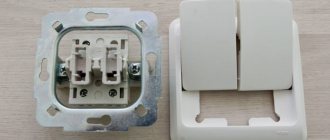
If we are talking about internal installation, then a mechanism is used that includes sliding strips that secure the device inside the wall hole.
The nest is made using perforators with crowns made of pobedite or industrial diamonds. First, a plastic or metal socket box is installed, and then the main structure.
By turning the screws of the spacer mechanism, the strips are set in motion and directed to opposite sides of the mounting hole, as a result of which the housing is securely attached to the wall.
Open type models are recommended for use in buildings with wooden coverings, where fastenings can be installed using self-tapping screws.
Type of contacts
The two-gang switch can be equipped with a screw or clamp type contact. In screw contacts, the exposed wire is fixed with a screw and a pair of metal plates, which is very reliable, but if the wire is not tightened or the cross-section is chosen incorrectly, the contacts will overheat greatly.
As a result of overheating, the clamp weakens, which requires regular tightening, since without this the contact will completely open or the elements of the device (wires, plastic) will catch fire.
In clamping models, the end of the wire is secured with a plate held by a spring, which allows you to create reliable, and most importantly, stable contact.
Housing material
The structural elements of the switches are made of plastic or ceramics. The permitted current and power must be indicated on each case.
Ceramic products cope well with thermal influences and are best suited for systems with high loads (10 Amps, 220 Volts, up to 2300 Watts).
Plastic modifications are designed for lower currents (3 - 6 Amperes).
Technical characteristics of the two-key hidden wiring switch Etude 10A white. SchE BC10-002B
Number of executive keys – 2. Rated voltage – 250 Volts. Material – Plastic. Rated current – 10 Amperes. Installation method – Hidden (under plaster). Surface – Untreated. Switched current of fluorescent lamps – 10 AX. Color – White. Presence of halogens – No. Suitable for IP degree of protection – IP20. Writing surface – No. Pushbutton, rocker switch – No
- Material Other
- White color
- Installation method Concealed installation
- Product code Schneider Electric#bc10002b
- Mounting type Screw fastening
- Nom. current 10 A
- Type/brand of material Other
- Halogen-free Yes
- Connection diagram 2-way switch
- Type of activation/control Key/button
- Type of configuration: Assembled with housing
- Push-return No
- Protective surface coating Other
- Surface type Glossy
- With field for the inscription No
- Backlight Without backlight
- Suitable for degree of protection (IP) IP20
- Nom. voltage 250 V
- We commute. load for luminescent lamps 10 AX
- Status signal contact No
- Connection method Screws. clamp/terminal
- Washing machine switch No
Similar products
| Product | Availability | Price |
| Switch 2-key OP Valentina A56-025 white-gold. Kuntsevo 7635 / Switch 2-cl. OP Valentina 10A IP20 A56-025 white/gold. Kuntsevo 7635 | 41 | 52.95 rub. |
| PRIMA S/U 1-key SWITCH 10A 250B, WHITE, wholesale package. Russia Schneider Electric / PRIMA S/U White 1-key switch 10A (assembled) (optical pack.) | VS1U-116-B | Schneider Electric | 561 | 55.30 rub. |
| PRIMA O/U 1-key SWITCH 10A 250V, WHITE, retail package. Russia Schneider Electric / 1-key switch. OP Prima 10A IP20 white. (retail pack) SchE VA1U-112-BI | 87 | 59.78 rub. |
| PRIMA S/U 1-key SWITCH 10A 250V, WHITE, retail package. Russia Schneider Electric / 1-key switch. SP Prima 10A IP20 white. (retail pack) SchE VS1U-116-BI | 82 | 59.83 rub. |
| PRIMA O/U 2-key SWITCH 10A 250B, WHITE, wholesale package. Russia Schneider Electric / PRIMA O/U White 2-key switch 10A (assembled) (optical package) | VA5U-214-B | Schneider Electric | 259 | 63.02 rub. |
| PRIMA O/U 2-key SWITCH MOUNTING PL.10A 250B, WHITE, wholesale package Russia Schneider Electric / Switch 2-key. OP Prima 10A IP20 white. (wholesale package) SchE VA5U-214M-B | 56 | 72.73 rub. |
| SKETCH O/U 1-key SWITCH 10 AX, WHITE, Russia Schneider Electric / SKETCH O/U White Switch 1-key | BA10-001B | Schneider Electric | 2236 | 73.01 rub. |
| PRIMA S/U 2-key SWITCH 10A 250B, WHITE, wholesale package. Russia Schneider Electric / PRIMA S/U White 2-key switch 10A (assembled) (optical pack.) | VS5U-218-B | Schneider Electric | 264 | 73.35 rub. |
| STUDY O/U 1-key SWITCH 10 AX, CREAM, Russia Schneider Electric / STUDY O/U Cream Switch 1-button | BA10-001K | Schneider Electric | 402 | 73.75 rub. |
| SKETCH OF S/U 1-key SWITCH 10 AX, WHITE, Russia Schneider Electric / SKETCH OF S/U White Switch 1-button | BC10-001B | Schneider Electric | 713 | 74.34 rub. |
- Office: Moscow, st. Kuskovskaya, 20A, office 706
- Tel Fax
Information about technical characteristics, stock availability, cost and images of goods is not a public offer.
Criteria for selecting a switch and other components
Before connecting a two-key switch, you should resolve the issue of the required network characteristics and type of wiring, power ratings of consumers, current strength and wire cross-section.
For a lighting fixture that has two groups of light bulbs (one 100-watt and three 40-watt), the power consumption will be P = 220 W. To calculate we use the formula:
For such a load, you will need a two-key switch with a 3 Ampere plastic housing and a wire cross-section of 0.75 millimeters.
In another case, it is necessary to provide lighting to a large room, where two groups of 8 light sources are used with three 80-watt fluorescent light bulbs for each lamp. Power characteristic: P = (80 x 3 x = 1920 W.
In the above example, you will need a ceramic two-gang switch with a load rating of 10 Amps. The wire cross-section is selected according to special tables available in the PUE. For the most part, a three-core copper cable with a cross-section of 0.75 - 1.5 millimeters is used.
The most common cable types:
- VVG - cable with three copper wires and PVC insulation in a common insulating sheath;
- PUNP - stands for flat installation wire. Used to create hidden wiring without grooves. It is fixed on the walls using brackets, and is masked on top with a layer of plaster. The cable is equipped with a double layer of PVC insulation and a plastic overall sheath.
08-03-591-05
08-03-591-05
| : | 100 . |
| 01. . 02. . 03. . 04. . |
2000
( ),
2009
. , .
, 2014 1
| (.) | (.-) | ||||
| 371,41 | 325,38 | 9,68 | 0,54 | 36,35 | 32,8 |
: 371,41 .
2020
08-03-591-05
, . -2001 2009
2000
.
, .
, – DefSmeta
, .
Device
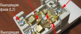
Two-key switches are three-pin mechanical devices. One of the contacts is common (fixed), and the other two are independent of each other. When pressure is applied to the key, the brass plates are brought to a common contact, resulting in the circuit being closed.
Two-key switches can be in six positions:
- two positions for one key (on/off);
- two positions for another key (on/off);
- two positions for both keys (on/off).
Using the above keys and their switching, lighting groups that are connected to the switch are controlled.
Connection diagram
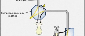
The two-button switch is connected to the electrical network through a distribution box. Three cables with copper conductors are sent there:
- from the switchboard;
- from the switch;
- from a lighting fixture with two groups of lamps.
The blue wire connects directly to the neutral of the lighting fixture. The red wire goes to the common contact of the switch. The green-yellow wire goes to the ground terminal of the chandelier. The remaining pair of moving contacts are connected through the junction box to the unoccupied terminals of the lighting fixtures.
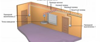
If you need to connect two light bulbs for different rooms, and the lighting is controlled by a two-key switch, four cables are directed to the junction box:
- from the switchboard;
- from the switch;
- from two lighting fixtures.
The connection diagram remains the same as above. The green-yellow ground wires are combined into a single contact. The contact is then routed to the switchboard grounding bus. Free wires are isolated and stored as a reserve for system expansion.
Note! It is important to follow the wire color rules only in two sections of the two-key switch connection diagram: from the switchboard the cable is directed to the distribution box, and from the lighting device to the distribution box. Starting from the output contacts of the switch, you can use wires of any color.
To test the system, use a multimeter, which should operate in ringing mode. Alternative measuring devices can also be used. Opening in the lighting circuit always occurs in phase (red wire).
This scheme is due to the need to ensure safety during repair work and when installing new consumers. The phase is found using an indicator screwdriver when turning on the circuit breaker on the switchboard.
Step-by-step installation instructions
Theoretically, the process of connecting a switching device can be divided into several main stages. Installation must begin with the cables. So, if the wiring is old enough, then it must be replaced with a new one. After this, you need to make the correct connection of the wires in the junction box, and then in the switch itself. To install a lamp or chandelier, you must use the manufacturer's instructions, specially designed for a particular light source.
The first stage - preparing the walls
The wall gating stage is very important and should only be skipped if new wiring with copper conductors of a suitable cross-section is installed. If there are any doubts, it is better to consult a specialist. If the wiring is old, be sure to replace it with a new one.
For lighting purposes, the most ordinary VVGng wire is suitable, the cross-section of which is 1.5 mm² square. If, along with lighting, sockets will be connected, then it is better to give preference to the same wire, but with a cross-section of 2.5 mm².
At the stage of preparing the walls, grooves and arrangement should be carried out, preparation of places where the installation of distribution boxes and socket boxes will be carried out. At this stage, experts also recommend installing an additional circuit breaker in the electrical panel. This separate device will not be superfluous, especially in situations where repairs are required on the lighting line. Using such a simple protective device, it will be possible to turn off only one circuit, while the rest will continue to operate in standard mode.
It is worth noting that in the case of wooden houses the type of wiring is significantly different, so a hidden installation method is not used, since this additionally increases the level of fire danger. In this regard, cables must be insulated as much as possible.
Wires are installed from the outside using special insulators. In this case, not internal, but surface-mounted switches are installed, however, the basic principle of connecting the cores to the terminals remains the same.
After the gating of walls of different materials is completed (this can be concrete, brick, or foam concrete), the grooves for laying wires must be sealed using a building mixture or alabaster. Then you can move on to plastering and decorative finishing of the walls. It is recommended to save the location of the wires on the diagram or drawing so that future repairs and replacement of wiring do not cause problems.
Second stage - connection in the junction box
The distribution box is the chamber in which the wiring and connection of the conductors is made. Depending on the type of sockets and switches, the type of connection diagram itself may vary significantly. And first of all, at this stage you should make the right choice of box. If previously metal products were a priority, today plastic analogues are produced that are more convenient and safer to install.
Wire connection diagram: twist the neutral wire from the panel with the zeros of the two connected lamps, and send the phase to the switch. Direct two output phases from the switch to the lamps - one for each
As already mentioned, there are external and internal types, but during the work it is the external products that are much easier to install. If it is necessary to disconnect the wires, for example, due to the replacement of an electrical installation, in order to gain access to the built-in distribution box, it will be necessary to dismantle the plaster, and then repair it.
In the case of an external box, its body is always visible. To gain access, simply unscrew the cover and carry out the required actions.
Recently, three-core wires are mainly used in the distribution box, therefore, as in the case of the neutral core, the earth is twisted. If the house still has old wiring, but it is quite reliable and in good working order, then there is no need to replace it. In this case, you should use the connection indicated in the diagram.
In general, there are several options for connecting wires. And the most common today are twisting with insulation in the future, as well as connection using terminal blocks. As for soldering, this method is used quite rarely. If you prefer to use terminal blocks, then you can give preference to a distribution box in which the terminals are already pre-installed.
The third stage - installation of lamps
Depending on a number of factors, the main method of installing a chandelier with two lamps or two separate lamps may vary. Among them are:
The easiest way to replace lighting equipment is when the main core is removed at the installation site, that is, for example, in the center of the room. In the case of new or suspended ceilings (stretch ceiling, plastic or even plasterboard), in order to install the lighting fixture, it will be necessary to install additional fasteners or mortgages.
When two phase wires are supplied to the lamp from a two-key switch, each of them is alternately connected to a specific light bulb. In addition, two neutral cores must be pulled from the distribution box, which are also distributed over two different lamps during the installation process.
If both bulbs are connected to the same wire, they will turn on and off simultaneously, so there is no point in installing a double switch.
By installing two separate lamps in different rooms or rooms, the basic principle of installation does not change, but the pulling of wires directly from the junction box changes. They should be directed in different directions, which is usually done if the rooms are next to each other. As for the distribution box itself, it is better to install it directly above the switch itself, at a distance of about 15-20 cm from the ceiling.
The fourth stage is the installation of the switch itself
The process of installing and connecting a two-key switch usually does not cause any complications. Installation is carried out in a socket box or directly into the wall with fixation with claws or screw connections.
If the lighting equipment has not two, but more lamps, which is not uncommon, then the connection must be made in groups. To do this, the number of lamps is divided into an equal or unequal number of groups, while the wire from contact L1 must be directed to one group, and from contact L2 to the other.
Each master divides into groups depending on his own preferences and the required degree of illumination of the room. When two power modes are required, that is, weak and bright light, then the first core can be run to one bulb, and the second to the rest. To achieve the highest level of lighting brightness, it will be enough to press both switch keys so that all the bulbs light up at the same time.
Features of installation on walls
For buildings made of reinforced concrete and brick, it is recommended to install a hidden type of wiring, and install distribution boxes and switches in pre-made grooves. It is recommended to choose plastic socket boxes. Such socket boxes are secured with screws and then covered with plaster solution.
A two-key switch can have two fixation options:
- A sliding mechanism in which the slats rest on opposite walls. It is important here not to overdo it when tightening the bolts, as the ceramic may crack.
- Galvanized plate located around the perimeter of the body. It has holes for bolts that secure the part to the socket box and the wall. Self-tapping screws and dowels are used for fixation.
Two-key switches (when it comes to external wiring) are often fixed with screws, just like distribution boxes. The wires are laid in plastic cable channels.